
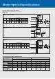
Specifications


8
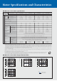
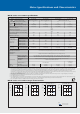
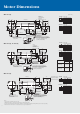
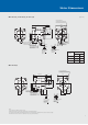
Motor Dimensions
●HF-SE52(B), HF-SE102(B), HF-SE152(B)
●HF-SE202(B)
Model
Variable dimensions
HF-SE52 (B)
HF-SE102 (B)
HF-SE152 (B)
(Note 3)
(Note 3)
(Unit: mm)
120 (154.5)
142 (176.5)
164 (198.5)
57.8
79.8
101.8
KLL
Notes:
1. Use a friction coupling to fasten a load.
2. Dimensions inside ( ) are for the models with electromagnetic brake.
3. Only for the models with electromagnetic brake. The electromagnetic brake terminals do not have the polarity.
4. For dimensions where there is no tolerance listed, use general tolerance.
B
C
A
D
Brake
Earth
W
U
V
Power supply connector
pin assignment
Motor flange
direction
Brake connector
pin assignment
Motor flange
direction
M130
ø165
112.5
ø145
13.5
58
12
3
L
39.7(45)
55
50
ø110h7
ø24h6
60.5(Note 3)
(Note 3)
(Note 3)
(Note 3)
(Note 3) (Note 3)
(Note 3)
79.9(Note 3)
29
45°
20.9
81.5
19.5
KL
Power supply connector
MS3102A18-10P
Brake connector
CM10-R2P (Note 3)
Encoder connector
MS3102A20-29P
4-ø9 mounting hole
Use hexagonal cap head bolts.
(Note 3)
(Note 3)
Brake
Earth
W
U
V
AB
CD
Power supply connector
pin assignment
Motor flange
direction
Brake connector
pin assignment
Motor flange
direction
45°
140.9
82
24.8
44
145(194.5)
79.8
79
96.9(Note 3)
68(Note 3)
ø
200
ø230
M176
18
75
3
40(47)
81.5
19.5
4-ø13.5 mounting hole
Use hexagonal cap head bolts.
Encoder connector
MS3102A20-29P
Brake connector
CM10-R2P (Note 3)
Power supply connector
MS3102A22-22P
ø114.3
0
-0.025
+0.010
0
ø35
(Note 3)
(Note 3)
(Note 3)
(Note 3)
(Note 3)
(Note 3)