MITSUBISHI ELECTRIC Graphic Operation Terminal User's Manual GT15-J71GP23-SX Art.
zSAFETY PRECAUTIONSz (Always read these precautions before using this equipment.) Before using this product, please read this manual and the relevant manuals introduced in this manual carefully and pay full attention to safety to handle the product correctly. The precautions given in this manual are concerned with this product. In this manual, the safety precautions are ranked as "DANGER" and "CAUTION".
[DESIGN PRECAUTIONS] DANGER z If a communication fails in data link, the faulty station holds the data link data generated before the communication error. Create an interlock circuit in the sequence program using the communication status information in order that the system will operate safely. Failure to do so may cause mis-outputs or malfunctions, resulting in accidents. Check the faulty station and the operation status during communication error by referring to the relevant manuals.
[INSTALLATION PRECAUTIONS] DANGER z Be sure to shut off all phases of the external power supply used by the system before mounting or removing this unit to/from the GOT. Not doing so can cause a unit failure or malfunction. CAUTION z Use this unit in the environment given in the general specifications of GT15 User's Manual. Not doing so can cause an electric shock, fire, malfunction or product damage or deterioration.
[WIRING PRECAUTIONS] CAUTION z Be careful not to let foreign matter such as dust or wire chips get inside the unit. This may cause a fire, failure or malfunctions. z Make sure to securely connect the cable to the connector of unit. Incorrect connection may cause malfunctions. z Make sure to fix communication cables and power cables to the unit by ducts or clamps.
[STARTUP AND MAINTENANCE PRECAUTIONS] CAUTION z Do not disassemble or modify any unit. This will cause failure, malfunction, injuries, or fire. z Do not touch the conductive areas and electronic parts of this unit directly. Doing so can cause a unit malfunction or failure. z Make sure to externally shut off all phases of the power supply before cleaning the unit and retightening unit mounting screws. Failure to do so may cause the unit to fail or malfunction.
REVISIONS * The manual number is noted at the lower right of the top cover. Print Date Jan., 2008 *Manual Number Revision IB(NA)-0800412-A First edition This manual confers no industrial property rights or any rights of any other kind, nor does it confer any patent licenses. Mitsubishi Electric Corporation cannot be held responsible for any problems involving industrial property rights which may occur as a result of using the contents noted in this manual.
CONTENTS 1. Overview ........................................................................................................ 1 2. Specifications ................................................................................................. 1 3. Part Names .................................................................................................... 3 4. Installation Procedure .................................................................................... 6 5. Precautions for Wiring Cables ...
Manuals The following shows manuals relevant to this product. Detailed Manual Manual number (Model code) Manual name GT15 User's Manual (Sold separately) SH-080528ENG (1D7M23) GOT1000 Series Connection Manual (Sold separately) SH-080532ENG (1D7M26) Relevant Manuals For relevant manuals, refer to the manuals in PDF format included in GT Designer2 and GT Works2.
1. Overview This manual explains the CC-Link IE controller network communication unit (hereinafter referred to as CC-Link IE communication unit). The CC-Link IE communication unit allows the GOT1000 series to function as a normal station on the CC-Link IE controller network. Refer to GT15 User's Manual for GOT to which this unit can be installed. When using the CC-Link IE controller network connection, make the communication setting to perform communication with programmable controllers.
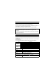
Item Max. number of networks Max. number of groups Transmission path Optical fiber specifications Standard Transmission loss (max.) Transmission band (min.) Connector specifications Standard Connection loss Polished surface Internal current consumption Weight Specification 239 32 Duplex loop 1000BASE-SX(MMF) fiber-optic cable IEC60793-2-10 Types A1a.1 (50/125 3.5 (dB/km) or less ( m multimode) = 850nm) 500 (MHz•km) or more ( = 850nm) Duplex LC connector IEC61754-20: Type LC connector 0.
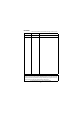
3. Part Names The following describes part names and descriptions of the CC-Link IE communication unit. 6) 3) 4) 3) 1) 5) 7) 6) 2) No. Name Description Indicates the operating status of the CC-Link IE communication unit.
(1) Indicator LED A LED indicates the status of the CC-Link IE communication unit and the communication status. When the LED is lighted up, there are two display formats, one for the normal mode and the other for the error mode. (1) Normal mode If any communication error occurs in the normal mode, specify the error cause by the [NETWK unit status display] screen of the GOT utility. Refer to GT15 User's Manual for details on the [NETWK unit status display] screen. LED name RUN SD RD ERR.
(2) Connector (IN side, OUT side) OUT Reverse loop, receiving OUT Forward loop, sending IN Forward loop, receiving IN Reverse loop, sending OUT IN 5
4. Installation Procedure (1) Power off the GOT. (2) Remove two extension unit covers of the GOT. (3) Attach the extension interface relay board to the extension interface 2 on the GOT. After the installation, detach the connector cover from the extension interface relay board. For GT155 , the extension interface relay board is not required. (4) Fit the CC-Link IE communication unit in the GOT case. Remove the connector cover.
(6) Fix the CC-Link IE communication unit by tightening two board fixing screws with a tightening torque of 0.36 to 0.48 N•m. 5) 6) (7) When installing an extension unit on the unit that has been installed, remove the connector cover and the stickers. When not installing an extension unit on the unit that has been installed, in order to avoid receiving electrostatic, stick accessory stickers to cover the top of mounting screws (4 places). Keep the connector cover fixed. Keep the accessory sticker stuck.
5. Precautions for Wiring Cables (1) Wire fiber-optic cables described in the following manual. • CC-Link IE Controller Network Reference Manual (2) For connecting fiber-optic cables to the unit, the bending radius of the cables must be within the specified range. For the details, check the specifications of the cables to be used. (3) When wiring a fiber-optic cable, do not touch the fiber core of the cable connector or unit connector, or let dirt or dust collect on it.
6. Wiring Method Normal station Power supply module IN Normal station n 120 Station No.n Station No.2 CPU module CPU module Control station Station No.1 Power supply module (1) Connection method Connect fiber-optic cables between OUT and IN side connectors as shown below. Note that there is no need to connect the cables in the order of station numbers.
7. External Dimensions (1) CC-Link IE communication unit 133(5.24) 3 (0.12) 98(3.86) 120(4.72) 2 (0.08) GOT main unit X 23.5 (0.93) 35(1.38) 44(1.73) 3 (0.12) 15 (0.59)) 2.5 (0.10) 15.5 (0.61) 11.5 (0.45) Dimensions of X when the CC-Link IE communication unit is mounted to the GOT. 15", 10.4" 21(0.83) 12.1" 18(0.71) 8.4", 5.7" 23(0.
MITSUBISHI ELECTRIC HEADQUARTERS EUROPEAN REPRESENTATIVES EUROPEAN REPRESENTATIVES MITSUBISHI ELECTRIC EUROPE B.V. EUROPE German Branch Gothaer Straße 8 D-40880 Ratingen Phone: +49 (0)2102 / 486-0 Fax: +49 (0)2102 / 486-1120 MITSUBISHI ELECTRIC EUROPE B.V. CZECH REPUBLIC Czech Branch Radlická 714/113a CZ-158 00 Praha 5 Phone: +420 (0)251 551 470 Fax: +420 (0)251-551-471 MITSUBISHI ELECTRIC EUROPE B.V.