MITSUBISHI ELECTRIC GX Configurator-PN 1.03 Configuration System for PROFINET IO Networks Software Manual Art.no.
About this Manual The texts, illustrations, diagrams and examples in this manual are only intended as aids to help explain the functioning, operation, use and programming of the open network configuration system MELSOFT GX Configurator-PN. Separate manuals are available for MITSUBISHI ELECTRIC's various series of MELSEC programmable logic controllers. This manual is only intended for users with experience in handling automation and communication networks.
Contents I Table of Contents 1 How to Use 1 2 PROFINET Controller ME1PN1FW-Q 2 2.1 Shared ................................................................................................................................... Memory PLC Interface 5 Managem ent ......................................................................................................................................................... Area 11 Cyclic Com .........................................................................
II 7.4 7.4.1 7.4.2 7.4.3 7.5 7.5.1 7.5.2 7.6 GX Configurator-PN Items ................................................................................................................................... View 116 'Item s' Menu ......................................................................................................................................................... 117 'Item s Properties' ............................................................................................................
How to Use 1 1 How to Use This manual... ...is a compact guide to using GX Configurator-PN software suitable both for beginners and experienced users upgrading from other systems. The manual includes explanations of the terms and structural concepts about the software and the configuration of an open network system. The manual provides a precise step-by-step description of how to use GX Configurator-PN including sample projects.
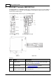
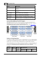
2 2 GX Configurator-PN PROFINET Controller ME1PN1FW-Q The ME1PN1FW-Q is a PROFINET RealTime (RT) communication master based on the hardware of the Q12DCCPU-V. The restrictions of the Q12DCCPU-V with regard to environmental, mechanical and electrical conditions apply. The following drawings indicate the parts of the ME1PN1FW-Q. Front face w ith cover closed Front face w ith cover open Side face Bottom face Parts list No.
PROFINET Controller ME1PN1FW-Q No.
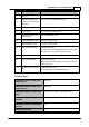
4 GX Configurator-PN Maximum number of total cyclic input data (1) 9228 bytes Maximum cycle time 512 ms Different IO-Devices can be configured with different cycle times RT communication RT Class 1 Alarm processing Read/Write Records Limited to 5448 bytes per request DCP (Discovery & Configure Protocol) Supported RPC (Remote Procedure Call) Supported (up to 4 fragments 5448 bytes) Baud rate 100 MBit/s Full-Duplex mode Data transport layer Ethernet II, IEEE 802.
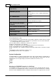
PROFINET Controller ME1PN1FW-Q 5 wing the PROFINET Controller. Note: if any of the intelligent modules requires specific settings in the 'I/O Assignment' configuration, these settings must first be set in the controlling Qn-CPU using the PLC programming software (GX Developer, GX IEC Developer, GX Works 2). After this the I/O assignment settings must be copied to the PROFINET Controller by updating the PROFINET Controller using the 'Update Parameters' dialog.
6 GX Configurator-PN Block Description Management Outputs Control and request flags from the Q-CPU to the PROFINET Controller Management Inputs Status and response flags from the PROFINET Controller to the Q-CPU Acyclic Outputs Request buffer for acyclic communication Acyclic Inputs Response buffer for acyclic communication Cyclic Outputs Outputs for I/O devices sent during cyclic data exchange Cyclic Inputs Inputs from I/O devices received during cyclic data exchange Access to Shared Memory
PROFINET Controller ME1PN1FW-Q (words) (words) N/A N/A N/A 0 N/A N/A N/A N/A N/A 1 N/A N/A N/A N/A N/A 2 N/A N/A 118 2100 854 3 10 000 13071 118 2100 1878 4 10 000 14095 118 2100 2902 5 10 000 15119 118 2100 3926 6 10 000 16143 118 2100 4950 7 10 000 17167 Profinet management Acyclic Buffer Size Max Input Size (words) High Speed Area (words) (words) 7 (kWords) For inputs: Calculated Minimal Size Address Start Address End (kWords) N/A N/A N/A
8 GX Configurator-PN Output Areas Offsets Calculation Block Start Address End Address Cyclic Outputs End Addr. - Output size +1 End Addr. Acyclic Outputs End Addr. - Output size 2100 + 1 End Addr. - Output size Mgmt. Outputs End Addr. - Output size 2100 - 118 + 1 End Addr. - Output size - 2100 Input Areas Offset Calculation Block Start Address End Address Cyclic Inputs End Addr. - Input size + 1 End Addr. Acyclic Inputs End Addr. - Input size 2442 + 1 End Addr. - Input size Mgmt.
PROFINET Controller ME1PN1FW-Q Shared Memory Structure Data from Qn-CPU to PROFINET Controller Size in Word Block number (for PLC) Global Variable Identifiers in Exported PLC Code Description High Speed Transmission Area (0x2710 – 0x5F0F) vPN_MGMT_OUTPUTS.IOC_STAR T_STOP 1 Allows to start or stop the PROFINET IO-Controller. vPN_MGMT_OUTPUTS.IOD_MGT_ Allow to set IO-Device 8 MODE management in automatic or manual mode. vPN_MGMT_OUTPUTS.
10 GX Configurator-PN vPN_ACYCLIC_REQ2 quest data (2 buffers max 1500 bytes each incl. header) 600 Reserved Reserved 1 vPN_CYCLIC_OUTPUTS.LIVE_WOR D_Y PLC to PROFINET Controller live register variable names for cyclic I/O data are user-defined output data sent to IODevices. The data size is variable up to 9898 bytes.
PROFINET Controller ME1PN1FW-Q 11 1 Device in error 61 Reserved 750 vPN_ACYCLIC_RES1 vPN_ACYCLIC_RES2 750 Buffers for acyclic request answer (2 buffers - max 1500 bytes each incl. header) 20 vPN_ACYCLIC_DIAG_INPUTS.AD V_DIAG_* Advanced diagnostic information about issues with PROFINET 256 Reserved for future time stamping Not Used. Reserved vPN_ACYCLIC_DIAG_INPUTS.CN F_CRC Configuration CRC value. vPN_ACYCLIC_DIAG_INPUTS.
12 GX Configurator-PN PROFINET firmware. firmware. If the IO-controller is starting or started, each connection will be automatically released by the firmware, even if the connection is in manual management. If the IO-controller is stopping (stop sequence), the firmware will continue the stop sequence up to the end and then will initiate again a start sequence. If the IO-controller is stopped, the IO-controller will be started.
PROFINET Controller ME1PN1FW-Q 13 IOD_START_STOP_DEV Registers With these 128 bits the PLC specifies, which command will be executed when the corresponding command handshake flag (see IOD_CMD_HSK_Y) is set. These registers are relevant only for devices, which are in manual management mode (see IOD_MGT_MODE). From CPU to PROFINET IO-Controller Global Variable Identifier IO-Device Values Number 0 1 Release connection Establish connection vPN_MGMT_OUTPUTS.IOD_START_STOP_DEV[0] 0 … ..
14 GX Configurator-PN Example for Starting PROFINET Communication If the data exchange mode for an IO device is set to 'automatic' (corresponding bit in IOD_MGT_MODE is 0), the cyclic data exchange with the device is automatically initiated, when the PROFINET Controller is started by setting IOC_START_STOP.
PROFINET Controller ME1PN1FW-Q 15 handshake mechanism exists to ensure consistency on all variables. This mechanism is optional and can be activated and deactivated per device. Input and Output Data Alignment The IO-device input and output areas in the buffer memory of the PROFINET Controller are word-aligned. PROFINET variables are located in the shared memory by respecting the following rules The data of each PROFINET IO-device is placed at an address on a word boundary, independent of its type.
16 GX Configurator-PN From CPU to PROFINET IO-Controller IO-Device Global Variable Identifiers Number vPN_MGMT_OUTPUTS.IOD_CONSIST[16] 16 … .. vPN_MGMT_OUTPUTS.IOD_CONSIST[31] 31 … … vPN_MGMT_OUTPUTS.IOD_CONSIST[116] 116 … .. vPN_MGMT_OUTPUTS.IOD_CONSIST[127] 127 Values 0 (default) 1 Therefore station-specific handshake flags are added to the shared memory, which block simultaneous access to the same input or output area by both the master and the PLC program.
PROFINET Controller ME1PN1FW-Q 17 From IO-Controller to CPU Global Variable Identifier Function vPN_MGMT_INPUTS.IOD_OUTPUT_HSK_X[0] New Outputs read (will be sent to the IO-device 0 during next exchange) … New Outputs read (will be sent to the IO-device n during next exchange) vPN_MGMT_INPUTS.
18 GX Configurator-PN Access to Input Data The following procedure must be followed, if the ‘Input consistency flag’ corresponding to the station is set.
PROFINET Controller ME1PN1FW-Q 19 Access to Output Data The following procedure must be followed, if the ‘Output consistency flag’ corresponding to the station is set. Cycle 1: 1. The PLC CPU detects that the output buffer is free because values of the handshake flags are equal (0:0 for cycle 1) 2. The PLC CPU writes the output data to the OUTPUT_DATA buffer 3. The PLC CPU toggles its handshake flag (0 -> 1 for cycle 1) 4.
20 GX Configurator-PN 5. The PROFINET Controller reads the output data from buffer memory 6. The PROFINET Controller signals that the output buffer is free by toggling its bit to equal that of the PLC CPU (1 -> 0 for cycle 2) 7. The cycle 2 is completed 2.1.3 Acyclic Communication Area The acyclic communication is an exchange of request and response messages between the PROFINET Controller and each IO-device station. The message exchange must be initiated by the controller.
PROFINET Controller ME1PN1FW-Q 21 Acyclic Request Header The request buffer consists of an header and a data buffer area. The same header is used whatever is the requested service. Consult each service detailed description to verify which fields are relevant. Word Offset ID Description RequestID ID of the request 2 ServiceID service identifier (see above) 3 Status Status of the request. shall always be equal to 0x55.
22 GX Configurator-PN Value: 0 to 1440. 12 PnDeviceID PROFINET Device ID 13 PnVendorID PROFINET Vendor ID 14-21 ARUUID Never used, must be set to 0. 22-29 Reserved Reserved Note: Each value is in little-endian- (i.e. Intel-) format. Acyclic Response Header The response buffer consists of a header and a data buffer area. The same header is used independently of the requested service. Consult each service detailed description to verify, which fields are relevant.
PROFINET Controller ME1PN1FW-Q 23 ServiceID The field 'ServiceID' marks the type of request.
24 GX Configurator-PN Word Offset ID Value 2 ServiceID 0x01 3 Status 0x55 4 DeviceID 0x0000 5 6 0x0000 API 7 8 SlotNumber 0x00 9 SubslotNumber 0x00 10 Index 0x00 11 Data length (byte) 0x0000 12 PnDeviceID 0x00 13 PnVendorID 0x00 14-21 ARUUID 0x00 22-29 Reserved Reserved (0x00) Response Positive Format (Status = 0) Word Offset ID Value RequestID Same as the request 2 ServiceID 0x01 3 Status 0x00 4 DeviceID 0x0000 6 Data length (byte) 0x0004 7 ErrorDe
PROFINET Controller ME1PN1FW-Q Word Offset ID Value 9 ErrorCode2 0x00 10-19 reserved 0x00 20 Nr IO-Devices Data 21 Number of IO-devices detected Response Negative Format Word Offset ID Value RequestID Same as the request 2 ServiceID 0x01 3 Status != 0x00 4 DeviceID 0x00 6 Data length 0x0000 7 ErrorDecode != 0x00 8 ErrorCode1 != 0x00 9 ErrorCode2 != 0x00 10-19 reserved 0x00 0 1 Header 5 Possible values for Status Value Comment 0 Status OK 1 Profinet stack
26 GX Configurator-PN IO-Device Detection This function allows to get for each IO-Device detected by a previous call to the service Network Detection, some information like IP configuration, MAC Address, Vendor ID, Device ID, Name of the IODevice and IO-Device type.
PROFINET Controller ME1PN1FW-Q Word Offset ID Value 3 Status 0x00 4 DeviceID 0x0000 6 Data length (byte) Size of the Data.
28 GX Configurator-PN Response Negative Format Word Offset ID Value RequestID Same as the request 2 ServiceID 0x02 3 Status != 0x00 4 DeviceID 0x0000 6 Data length (byte) 0x00 7 ErrorDecode != 0x00 8 ErrorCode1 != 0x00 9 ErrorCode2 != 0x00 10-19 Reserved 0x00 0 1 Header 5 Possible Values for Status Value Comment 0 Status OK 1 Profinet stack not started 4 Reception buffer too small (stack internal error) 5 No more IO-Device 6 “Network detection” service never call
PROFINET Controller ME1PN1FW-Q Request format Word Offset ID Value RequestID PLC value 2 ServiceID 3 3 Status 0x55 DeviceID Shall contain the IP address API API number used to perform the read 8 SlotNumber Slot number targeted 9 SubslotNumber Sub-slot number targeted 10 Index Index of the record block 11 Data length (byte) 0 12 PnDeviceID DeviceID of the IO-Device 13 PnVendorID VendorID of the IO-Device 14-21 ARUUID 0 22-29 Reserved Reserved (0) 0 1 4 5 6 7 Response
30 GX Configurator-PN Word Offset ID Value 6 Data length (byte) Buffer data size 7 ErrorDecode 0x00 8 ErrorCode1 0x00 9 ErrorCode2 0x00 10-19 reserved 0x00 .. Data ID Value Request ID Same as the request 2 ServiceID 3 3 Status != 0 Device ID 0 6 Data length (byte) 0 7 ErrorDecode != 0 8 ErrorCode1 != 0 9 ErrorCode2 != 0 10-19 reserved 0 20 .. .. Data .. .. ..
PROFINET Controller ME1PN1FW-Q Possible Values for Status Value Comment 0 Status OK, function 1 Profinet stack not started 2 No ethernet link 3 No IO-Device detected 4 Reception buffer too small (internal stack error) 6 Device not connected 7 Device not configured 8 Profinet error Record Block Explicit Write (connected) Request format Word Offset ID Value RequestID PLC value 2 ServiceID 4 3 Status 0x55 DeviceID Requested device API API number used to perform the write 8 S
32 GX Configurator-PN Word Offset ID Value 14-21 ARUUID 0 22-29 Reserved Reserved (0) 30..
PROFINET Controller ME1PN1FW-Q Word Offset ID Value 6 Data length (byte) 0x00 7 ErrorDecode != 0x00 8 ErrorCode1 != 0x00 9 ErrorCode2 != 0x00 10-19 reserved 0x00 5 Possible Values for Status Value Comment 0 Status OK, function 1 Profinet stack not started 2 No ethernet link 3 No IO-Device detected 6 Device not connected 7 Device not configured 8 Profinet error see others status Record Block Explicit Read (connected) Request format Word Offset ID Value RequestID PLC
34 GX Configurator-PN Word Offset ID Value 8 SlotNumber Slot number targeted 9 SubslotNumber Subslot number targeted 10 Index Index of the record block 11 Data length (byte) 0 12 PnDeviceID 0x00 13 PnVendorID 0x00 14-21 ARUUID 0x00 22-29 Reserved Reserved (0x00) 7 Response positive format (Status = 0) Word Offset ID Value Request ID Same as the request 2 ServiceID 0x05 3 Status 0x00 Device ID IP address 6 Data length (byte) Buffer data size 7 ErrorDecode 0x00
PROFINET Controller ME1PN1FW-Q Word Offset ID Value Response Negative Format Word Offset ID Value RequestID Same as the request 2 ServiceID 0x05 3 Status != 0x00 4 DeviceID 0x00 6 Data length (byte) 0x00 7 ErrorDecode != 0x00 8 ErrorCode1 != 0x00 9 ErrorCode2 != 0x00 10-19 reserved 0x00 0 1 Header 5 Possible values for Status Value Comment 0 Status OK, function 1 Profinet stack not started 2 No ethernet link 3 No IO-Device detected 4 Reception buffer too smal
36 GX Configurator-PN Alarm Request This service allows PLC to ask to PROFINET stack the alarm received from a specific IO-Device. This service has to be used in relation with the IOD_MGT_ALARM and IOD_ALARM_IND Alarm registers see 3.1.6.
PROFINET Controller ME1PN1FW-Q Word Offset ID Value 8 ErrorCode1 0x00 9 ErrorCode2 0x00 10-19 reserved 0x00 API API number used to perform the alarm 22 Priority Alarm priority 23 Type Alarm type 24 Slot number Slot number of the alarm 25 SubSlot number Subslot number of the alarm 26 Specifier Alarm specifier Module ident number Module ID of the Alarm SubModule ident number submodule ID of the Alarm 31 Data length Data Size in byte Data Data 0 to 1432 bytes 20 21 Data
38 GX Configurator-PN Value (hexadecimal) Meaning 0x0006 Update 0x0007 Media Redundancy 0x0008 Controlled by supervisor. Logical “Pull” of a submodule to withdraw ownership 0x0009 Released.
PROFINET Controller ME1PN1FW-Q bits Description Value gnosis 0x01: Diagnosis available Diagnostis sub-module 0x00: No diagnosis available 14 Reserved 0x00 15 AR diagnostis 0x00: No diagnosis available 13 0x01: Diagnosis available 0x01: Diagnosis available Response Negative Format Word Offset ID Value Request ID Same as the request 2 ServiceID 0x06 3 Status != 0x00 4 Device ID 0x00 6 Data length (byte) 0x00 7 ErrorDecode != 0x00 8 ErrorCode1 != 0x00 9 ErrorCode2 != 0
40 GX Configurator-PN Value Comment 9 No Alarm for this device Alarm Ack This service sends to the IO-Device the Ack alarm frame. This service has to be used in relation with the IOD_MGT_ALARM and IOD_ALARM_IND Alarm registers.
PROFINET Controller ME1PN1FW-Q Word Offset ID Value 2 ServiceID 0x07 3 Status 0x00 Device ID Requested device 6 Data length (byte) 0x00 7 ErrorDecode 0x00 8 ErrorCode1 0x00 9 ErrorCode2 0x00 10-19 reserved 0x00 ID Value RequestID Same as the request 2 ServiceID 0x07 3 Status != 0x00 DeviceID 0x00 6 Data length (byte) 0x00 7 ErrorDecode != 0x00 8 ErrorCode1 != 0x00 9 ErrorCode2 != 0x00 10-19 reserved 0x00 1 4 5 Response negative format Word Offset 0 1
42 GX Configurator-PN Value Comment 0 Status OK 1 Profinet stack not started 7 Device not configured 8 Profinet error see others status 9 No alarm for this device IO-Device Information Request format Word Offset ID 0 Value PLC value RequestID 1 2 ServiceID 0x08 3 Status 0x55 DeviceID Requested device API 0x00 8 SlotNumber 0x00 9 Subslot Number 0x00 10 Index 0x00 11 Data length (byte) 0x00 12 PnDeviceID 0x00 13 PnVendorID 0x00 14-21 ARUUID 0x00 22-29 Reserv
PROFINET Controller ME1PN1FW-Q Response positive format (Status = 0) Word Offset ID Value Request ID Same as the request 2 ServiceID 0x08 3 Status 0x00 Device ID Requested Device 6 Data length (byte) 0x24 7 ErrorDecode 0x00 8 ErrorCode1 0x00 9 ErrorCode2 0x00 10-19 reserved 0x00 0 1 4 Header 5 20 21 Mac address 22 23 IP address 24 25 26 Data 27 28 Input @ area in High Speed Area output @ area in High Speed Area 29 Input length 30 Output Length 31 Refresh period
44 GX Configurator-PN Word Offset ID Value 34 State (Connected/Not Connected) 35 Management (Manual Automatic) 36 Current Profinet Status 37 Response negative format Word Offset ID Value Request ID Same as the request 2 ServiceID 8 3 Status != 0 4 Device ID 0 6 Data length (byte) 0 7 ErrorDecode != 0 8 ErrorCode1 != 0 9 ErrorCode2 != 0 10-19 reserved 0 0 1 Header 5 Possible values for Status Value Comment 0 Status OK, function 1 Profinet stack not started 10
PROFINET Controller ME1PN1FW-Q - Function has to be called several times to get several alarm description - The older alarm is returned first Request format Word Offset ID Value RequestID PLC value 2 ServiceID 0x09 3 Status 0x55 DeviceID Requested device API 0 8 SlotNumber 0 9 SubslotNumber 0 10 Index 0 11 Data length (byte) 0 12 PnDeviceID 0 13 PnVendorID 0 14-21 ARUUID 0 22-29 Reserved Reserved (0) 0 1 4 5 6 7 Response positive format (Status = 0) Word Offset ID
46 GX Configurator-PN Word Offset ID Value 6 Data length (byte) 0 7 ErrorDecode 0x00 8 ErrorCode1 0x00 9 ErrorCode2 0x00 10-19 reserved 0x00 Date Date of the PROFINET Controller when the frame has been received Time Time of the PROFINET Controller when the frame has been received 5 20 21 22 23 24 Alarm Type 25 API 26 Data 27 Alarm Priority 28 ModuleID 29 30 SubModuleID 31 API number used to perform the alarm ID of the module. Manufacturer dependant. ID of the module.
PROFINET Controller ME1PN1FW-Q Word Offset ID Value 2 ServiceID 0x09 3 Status != 0x00 DeviceID 0x00 6 Data length (byte) 0x00 7 ErrorDecode != 0x00 8 ErrorCode1 != 0x00 9 ErrorCode2 != 0x00 10-19 reserved 0x00 47 4 5 Possible values for Status Value Comment 0 Status OK, function 1 PROFINET stack not started 2 No ethernet link 7 Device not configured 8 PROFINET error see others status 9 No alarm in log Alarm Management A IO-device is able to send alarms to the IO-c
48 GX Configurator-PN From CPU to PROFINET IO-Controller IO-Device Global Variable Identifier vPN_MGMT_OUTPUTS.IOD_MGT_ALARM[0] … Number 0 .. Values 0 1 Automatic Manual .. 15 .. Automatic vPN_MGMT_OUTPUTS.IOD_MGT_ALARM[16] 16 Automatic … .. vPN_MGMT_OUTPUTS.IOD_MGT_ALARM[31] 31 .. Automatic … … …. …. vPN_MGMT_OUTPUTS.IOD_MGT_ALARM[116] 116 Automatic … .. vPN_MGMT_OUTPUTS.IOD_MGT_ALARM[127] 127 .. Automatic Manual .. vPN_MGMT_OUTPUTS.IOD_MGT_ALARM[15] Manual Manual ..
PROFINET Controller ME1PN1FW-Q 49 Note: a ring buffer exists for each device. This ring buffer stores up to seven alarms for each IO-device. Each incoming alarm is logged in this ring log buffer, from which the PLC can read using acyclic requests. 2.1.4 Network Diagnostics PROFINET IO Controller Status The bits in these two words provide information on the IO-controller stack state. From PROFINET IO-Controller to CPU Values Global Variable Identifier vPN_MGMT_INPUTS.
50 GX Configurator-PN From PROFINET IO-Controller to CPU Values Global Variable Identifier 0 1 ning. Possible combinations of the flags IOC_STS_CONFIG_OK, IOC_STS_CONFIG_DOWNLOADING, IOC_STS_KEYFILE_ERROR and IOC_STS_STARTED with their respective meaning are Flags Set Comment no flag set There is no configuration inside the PROFINET Controller. To use PROFINET download a configuration IOC_STS_KEYFILE_ERROR BAD pnengine.dat. IOC_STS_CONFIG_DOWNLOADIN G A new configuration download is pending.
PROFINET Controller ME1PN1FW-Q 51 PROFINET IO-Controller to CPU IO-Device Global Variable Identifier Number vPN_MGMT_INPUTS.IOD_CONN_STS[116] 116 … .. vPN_MGMT_INPUTS.IOD_CONN_STS[127] 127 Values 0 1 IOD_ERR_STS Registers The following 128 bits indicate for each IO-device, whether an error has occurred. PROFINET IO-Controller to CPU IO-Device Global Variable Identifier vPN_MGMT_INPUTS.IOD_ERR_STS[0] … vPN_MGMT_INPUTS.IOD_ERR_STS[15] number Values 0 1 No Error Error 0 ..
52 GX Configurator-PN Device Advanced Status (IOD_ADV_STS Registers) For each IO-device a byte in the variable 'vPN_ACYCLIC_DIAG_INPUTS.IOD_ADV_STS' contains the detailed status error code, when the corresponding bit in IOD_ERR_STS is set. Each element in the word array 'IOD_ADV_STS' contains the status codes of two devices, the status of the device with an odd index is placed in the low byte, the status of the device with an even index is placed in the high byte.
PROFINET Controller ME1PN1FW-Q 53 From IO-Controller to CPU Global Variable Identifier Contents 0: Stack running well vPN_ACYCLIC_DIAG_INPUTS.ADV_DI AG_ERR_CODE 1: MAC address check fails PROFINET stack error code 2: MAC file encrypted not found 3: Assert 4: Error system vPN_ACYCLIC_DIAG_INPUTS.ADV_DI AG_ERR_CODE2 PROFINET stack error code (high word) vPN_ACYCLIC_DIAG_INPUTS.ADV_DI AG_ADD_INFO Additional information depending on the main error code.
54 GX Configurator-PN ween the PLC program and the PROFINET Controller. By default this mechanism is not activated (LIVE_WORD_X =0) The following scenario applies: By default the LIVE_WORD_Y register is set to 0, meaning that no check is activated. To activate the mechanism, PLC sets LIVE_WORD_Y to 1 or to any value different from 0 The IO-controller reads the LIVE_WORD_Y value in an interval of 500 ms. If the value is identical three consecutive times (1.
PROFINET Controller ME1PN1FW-Q RUN STOP 55 PROFINET stack is in STOP. Output data = old values and IOPS and IOCS set to BAD Input data are updated in the high speed area STOP RUN PROFINET stack is in RUN. Output data = old values an IOPS and IOCS set to GOOD Input data are updated in the high speed area STOP STOP PROFINET stack is in STOP. Output data = old values an IOPS and IOCS set to BAD Input data are updated in the high speed area 2.2 LED Display 2.2.
56 2.2.2 GX Configurator-PN State Meaning Orange slow blink All IO-devices in automatic mode are connected. All IO devices in manual mode are not connected. However, some configuration mismatches exist. Orange rapid Blink All IO-devices in automatic mode are connected. Some IO devices in manual mode are connected, some are not connected. However, some configuration mismatches exist. 7-Segment LED Display The 7-segment display is located on the front of the ME1PN1FW-Q.
PROFINET Controller ME1PN1FW-Q User LED 57 7 segment value Meaning 11 CNFMAST.001 is missing in folder \RAM\Profinet\Default 12 CNFDEVIC.001 is missing in folder \RAM\Profinet\Default 13 CNFNAME.001 is missing in folder \RAM\Profinet\Default 14 copycross10.bin is missing in folder \RAM\Profinet\Default 15 CNFMAST.001 is missing in folder \RAM\Profinet 16 CNFDEVIC.001 is missing in folder \RAM\Profinet 17 CNFNAME.001 is missing in folder \RAM\Profinet 18 copycross10.
58 3 GX Configurator-PN Getting to know GX Configurator-PN GX Configurator-PN Concept GX Configurator-PN (GXPN) is the configuration tool for PROFINET I/O interfaces in MITSUBISHI PLCs. It provides functions for defining a PROFINET I/O network, validating the configuration and downloading it to the respective PLC module via a MITSUBISHI automation network. GX Configurator-PN is capable of downloading configuration data to the PROFINET I/O module via a variety of different communication types.
Installation 4 59 Installation Before You Begin Copyright Important Notice: This software is protected by copyright. By opening the distribution disks package you automatically accept terms and conditions of the license agreement. You are only permitted to make one single copy of the original distribution disks for your own backup and archiving purposes.
60 4.2 GX Configurator-PN Software Installation GX Configurator-PN Setup To install the GX Configurator-PN software you need to have Microsoft ® Windows properly installed. You may require administrator privileges when installing the software. If an older version of GX Configurator-PN is already installed, uninstall it first. After the de-installation please start the installation of the new version.
Installation 61 5. Follow the given instructions that guide you through the installation procedure. Continue with Next. 6. The licensing agreement is displayed. Please read these terms carefully. If you accept the license agreement, you can proceed with the installation by clicking Next. Otherwise the installation is aborted.
62 GX Configurator-PN 7. Enter your name, organization and the product serial number. Click on Next to proceed. 8. Enter the destination folder where you want the GX Configurator-DP software to be installed (default C:\Program Files\MELSOFT\GX Configurator-PN 1.03). If you want to install to a different directory, click on Change and select the installation directory. If you agree with the default setting, just click on Next.
Installation 63 9. The installation is started by pressing the Install button. 10. After pressing the 'Install' button the installation is started. Progress bars will inform you about the setup status.
64 GX Configurator-PN 11. After the installation has been successfully completed, you see the following message For the communication with the PROFINET Controller the 'Discovery and Configuration Protocol' (DCP) communication driver must be attached to the local Ethernet interface, which is connected to the controller. The exact steps depend on the operating system used. Please see section 'Installing the DCP Protocol Driver' for details.
Installation 4.3.1 65 Windows XP 1. Open the Control Panel and double click "Network Connections" to open the Network Connection Settings.
66 GX Configurator-PN 2. Right click "Local Area Connection" and select "Properties" to open the "Local Area Connection Properties". 3. Click "Install" to open the "Select Network Component Type" dialog.
Installation 67 4. Select "Protocol" from the List and click "Add..." to open the "Select Network Protocol" dialog. 5. Select "MITSUBISHI ELECTRIC" from the "Manufacturer" List and after that "MITSUBISHI DCP driver" from the "Network Protocol" List. Then click "OK" to confirm the selection. The "MITSUBISHI DCP driver" is now added to the Protocol List in the dialog "Local Area Connection Properties".
68 4.3.2 GX Configurator-PN Windows Vista 1. Open the Control Panel and click "View network status and tasks" to open the "Network and Sharing Center". 2. Click "View Status" of the "Local Area Connection" to open the "Local Area Connection Status".
Installation 69 3. Click "Properties" to open the "Local Area Connection Properties". 4. Answer the "User Account Control" with "Continue" to step further to the "Local Area Connection Properties".
70 GX Configurator-PN 5. Click "Install..." to open the "Select Network Feature Type" dialog. 6. Select "Protocol" from the List and click "Add..." to open the "Select Network Protocol" dialog.
Installation 71 7. Select "MITSUBISHI ELECTRIC" from the "Manufacturer" List and after that "MITSUBISHI DCP driver" from the "Network Protocol" List. Then click "OK" to confirm the selection. The "MITSUBISHI DCP driver" is now added to the Protocol List in the dialog "Local Area Connection Properties". Note: After adding the driver the operating system must be restarted to enable online operation for GX Configurator-PN. 4.3.3 Windows 7 1.
72 GX Configurator-PN 2. Click "Local Area Connection" to open the "Local Area Connection Status". 3. Click "Properties" to open the "Local Area Connection Properties".
Installation 73 4. Click "Install..." to open the "Select Network Feature Type" dialog. 5. Select "Protocol" from the List and click "Add..." to open the "Select Network Protocol" dialog.
74 GX Configurator-PN 6. Select "MITSUBISHI ELECTRIC" from the "Manufacturer" List and after that "MITSUBISHI DCP driver" from the "Network Protocol" List. Then click "OK" to confirm the selection. The "MITSUBISHI DCP driver" is now added to the protocol list in the dialog "Local Area Connection Properties". Note: After adding the driver the operating system must be restarted to enable online operation for GX Configurator-PN. 4.3.4 Windows 8 1.
Installation 2. Click "Ethernet" to open the "Ethernet Status". 3. Click "Properties" to open the "Ethernet Properties".
76 GX Configurator-PN 4. Click "Install..." to open the "Select Network Feature Type" dialog. 5. Select "Protocol" from the List and click "Add..." to open the "Select Network Protocol" dialog.
Installation 77 6. Select "MITSUBISHI ELECTRIC" from the "Manufacturer" List and after that "MITSUBISHI DCP driver" from the "Network Protocol" List. Then click "OK" to confirm the selection. The "MITSUBISHI DCP driver" is now added to the protocol list in the dialog "Local Area Connection Properties". Note: After adding the driver the operating system must be restarted to enable online operation for GX Configurator-PN. 4.
78 GX Configurator-PN 5.
Installation 79 6. update the refresh settings on both the controlling Qn-CPU and the PROFINET Controller in the 'PLC Settings' dialog.
80 5 GX Configurator-PN Getting Started Below are the main steps, which are required to configure a PROFINET I/O master module. Start GX Configurator-PN 1. Start GX Configurator-PN via the shortcut in the Programs menu. The default location of the shortcut is Programs \ MELSOFT Application \ GX Configurator-PN 1.03 \ GX Configurator-PN 1.03. Start a New Project 1. In the main menu File select Configuration Manager.
Getting Started 81 2. in the Configuration Manager press New to create a new configuration project After closing the 'Configuration Manager' dialog the 'Add New ME1PN1FW-Q' dialog is displayed. The user must select the local network interface, the ME1PN1FW-Q is connected to. The user can then choose to obtain the network address of the module either automatically or manually. For details see the description of the 'Add New ME1PN1FW-Q' dialog.
82 GX Configurator-PN 3. the inserted module is now displayed in the network view and slaves can be added by drag&drop from the 'Device Library'. or by scanning the network for slave devices using the 'Network Detection View' .
Getting Started 83 4. the configuration of a slave can be edited by selecting 'Properties' from the slave context menu. 5. after completing the network settings the configuration can be downloaded to the ME1PN1FW-Q with the item 'Download Configuration' from the 'File' menu.
84 GX Configurator-PN 6. whenever the I/O configuration has been changed the user is prompted to update the offsets in the I/O mapping within the 'PLC Settings' Dialog.
Main Menu 6 85 Main Menu Starting GX Configurator-PN Select GX Configurator-PN from the Windows Start menu. The default shortcut is Start -> Programs -> MELSOFT Applications -> GX Configurator-PN 1.03 -> GX ConfiguratorPN 1.03 Main menu The main menu offers the following pull-down menus.
86 GX Configurator-PN Command Description on projects Save Save the current configuration List and Print Opens the ‘Preview and Print Listings’ dialog PLC Settings Opens the 'PLC Settings' dialog Download Configuration Download the configuration to the PROFINET controller Download Configuration in Memory Card Download the configuration to the memory card in the PROFINET controller Preferences Selects the user interface layout, active ‘Advanced Mode’ Message View Functions related to the ‘Me
Main Menu 87 Command Description Workspace Toggles the display of the 'Configuration View', the 'Device Library View' and the 'Network Detection View' Output Window Toggles the display of the 'Message View' window Advanced Mode Toggles 'Advanced Mode' Command 'Message View' This item opens the 'Message View' menu. Command 'Exit' You can use this menu command to quit the software.
88 6.
User Interface 7 User Interface 7.1 Device Library 89 The device library is the local collection of descriptions for types of PROFINET I/O devices. The parameters used for configuring an IO-Device are contained in a GSDML file (Generic Station Description Markup Language), commonly called a GSD. A GSD may contain one or more IO-Device descriptions. The device library is used to store GSD files and to provide a graphic view.
90 GX Configurator-PN Adding IO-Device Types to the Library The 'GSDML Management' wizard lets you add one or more IO-Devices to the library. This wizard may be accessed via the button or via the menu item ‘Add…’ from the context menu of the device library or the ‘Library’ submenu in the main menu. For details see 'Add GSDML Files'. 7.1.
User Interface Name Description ries in the device library Available sort keys are: By Category: Displays IO-Devices according to their main type then their secondary type. This sort is based on the "Main Family" and "Product Family" fields in the GSD for the IO-Device. By Manufacturer: Displays the IODevice by manufacturer. This sort is based on the "VendorName" field in the GSD for the IO-Device. By File name: Displays the IO-Devices according to the GSD filename.
92 7.1.2 GX Configurator-PN 'GSDML Management' Dialog This wizard-style dialog is opened to add device types defined in GSDML files to the device library.
User Interface 93 Name Description Choices / Range Default Add File(s) Add one or more GSDML files Selected / not selected Selected Selected / not selected Not selected Use the [Browse] button to select the files. If the file already exists, the 'File Already Exists' warning is displayed. Add all the GSDML from the Directory Add the GSDML files in a specified directory and (optionally) its subdirectories Use the [Browse] button to select the files.
94 GX Configurator-PN 'Add GSD File Completed' Page After adding one or several GSD files to the library, the next page shows for each selected GSD file, whether it has been added to the library or not.
User Interface 95 Name Description Choices / Range Default Columns 'Family Name', 'Schema Version', 'Manufacturer', 'File Date' and 'File Time' Additional information taken from the GSDML file - - View Selected File Open the selected GSDML file in the default text editor - - Back Go back to the previous page - - Next Proceed to the next page to end the wizard - Default button Cancel Close wizard and discard changes - - Help Open online help - - (c) 2013 MITSUBISHI ELECTRIC CORP
96 7.1.3 GX Configurator-PN 'Device Type Properties' Dialog A double-click on a device type entry in the 'Device Library' tree opens a dialog with information from the respective GSDML file. Name Description Choices / Range Default Tree Structured display of the GSDML file contents - - Check GSDML Checks, whether GSDML file contents comply to the specification (i.e.
User Interface 7.
98 GX Configurator-PN Network Tree Network components with icons like this: configuration. are IO-Controllers They cannot be used in the current Network detection will carry out an implicit read request to the IO-Device to find out the configuration of the IO-Device's slots and sub-slots. Certain IO-Devices do not support this request and must therefore be configured manually.
User Interface 7.2.
100 GX Configurator-PN Command 'Properties' Opens the view with the properties of the selected device. 7.2.2 Online Action Tool The ‘Online Action’ tool is started via either the menu item ‘Online Action’ or by pressing the button. When the tool is started, it issues requests to detect PROFINET stations on the network.
User Interface 101 Name Description Choices / Range Default Scanning If checked, the network nodes list is refreshed every 3 seconds. Otherwise the list is not refreshed again. - - MAC Address Ethernet address of the selected device - - Device Type Type of the selected device - - Factory Reset Sends a DCP request to the IO-Device telling it to restart with its factory default settings.
102 GX Configurator-PN Name Description Choices / Range Default - - Note: if an IO-Device is configured in DHCP mode and a connection is established, the IOController compares the TCP/IP configuration of the IO-Device with that contained in the configuration of the IO-Controller. If they differ, the connection cannot be established. DHCP Based on MAC address: the identifier used for obtaining the IP configuration from the DHCP server will be the MAC address of the IO-Device.
User Interface Name Description 103 Choices / Range Default ‘DCP_FlashOnceSignalUnit’ tag, the text from the GSDML file indicates the device behaviour when it receives a DCP flash command. Device Blinking The ‘Blinking Device’ dialog is displayed and DCP blink commands are sent to the device.
104 GX Configurator-PN the size of a label varies from 1 to 63 characters total size (sum of all label and [.] character) varies from 1 to 240 characters the allowed characters are [a-z0-9], upper-case letters are prohibited labels may not start with [-] labels may not terminate with [-] labels may not start with [port-xyz] or [port-xyz-abcde] where a,b,c,d,e,x,y,z = 0..
User Interface 105 the MAC address of the IO-Device. Station name: the identifier used for obtaining the IP configuration from the DHCP server will be the name of the IO-Device. Client identifier: the identifier used for obtaining the IP address from the DHCP server will be the string entered in the client identifier field.
106 GX Configurator-PN gnostic tool. This tool gives a first level diagnosis of the status of the current configuration. When the diagnostic mode is enabled, the configuration cannot be changed. It is in read-only mode. Once enabled, the diagnostic view shows the current status of the connection for each IO-Device. Indicates that the IO-Device is connected Indicates that the IO-Device is disconnected but that a connection phase is under way Indicates that the IO-Device is not connected.
User Interface Command Description opens the ‘PROFINET I/O Device Properties’ dialog Start Console Diagnostic Start diagnostic mode Stop Console Diagnostic Stop diagnostic mode Options Opens the ‘Display Option’ dialog Properties The effect of this menu item depends on the node, which is selected in the network tree. 7.3.
108 GX Configurator-PN Name Description Choices / Range Default Display device IP ad- If enabled, displays the IP address of the device Active / Inacti- Inactive dress in the tree in the current configuration tree. ve Display device number in the tree If enabled, displays the number of the device in the current configuration tree.
User Interface 109 DCP section Request time-out Sets the maximum time from the IO-Controller sending a DCP request from the reply. It also sets the listening time of the IOController to the DCP identification request Number of request retries Sets the maximum number of times a DCP request is repeated following a timeout. RTA (Real Time with Acknowledgment) section Request time-out Sets the maximum period separating the time from the IO-Controller sending a RTA request and the reply.
110 GX Configurator-PN RPC section - Client Maximum number of pings Sets the maximum number of pings while awaiting a response. Maximum number of re-sends Sets the maximum number of times an RPC frame is repeated (question or response). Timeout on CANCEL request Sets the maximum time from the IO-Controller sending an RPC cancel request to the reply. Timeout on Fragment Acknowled- Sets the maximum time separating the IO-Controller sending ge an RPC ACK request from the reply.
User Interface 7.3.4 111 IP Address Manager This dialog provides access to the network address settings of the PROFINET Controller and to the 'IP Address Manager'.
112 GX Configurator-PN Name Description Choices / Range Default PROFINET is not an IP-based protocol. It will not be possible to route I/O exchanges through a gateway. Controller Name: PROFINET name of the IO-Controller. Description Provides help on the selected field. read-only - OK Close dialog and save changes - Default button Cancel Close dialog and discard changes - - Help Open online help - - Note: after changing the controller IP address the configuration must be downloaded.
User Interface 113 IP Address Manager The ‘IP Address Manager’ service manages the IP address allocation for IO-Devices present in the configuration. Name Description Choices / Range Default Address Ranges define one or more IP address ranges - - IP addresses from these ranges will be distributed by the console when an IO-Device is added.
114 GX Configurator-PN Address Assignments To reserve IP addresses for predefined IO-Device names - - - - not selected This is useful for IO-Devices with addresses which must remain fixed. When the respective IO-Device is inserted into the current configuration, the corresponding IP address will automatically be assigned to it. Scan Get a list of I/O devices on the network The button is used to copy device name and IP address to the ‘Configured Assignments’ list.
User Interface 115 is asked, whether the IP address should also be changed online on the PN controller. The IP address can only be changed on the controller, if the PROFINET cyclic data exchange is stopped. If the data exchange has been started, the attempt to change the IP address online causes an error entry in the log. The data exchange can be stopped via the 'PROFINET Controller Status' dialog.
116 7.4 GX Configurator-PN Items View Lists the I/O points of the module selected in the network configuration view. The user can select an item and change its name in the 'Items Properties' Dialog The context menu in the view corresponds to the 'Items Menu' in the main menu. 'Item Properties' Dialog This dialog is opened by double-clicking an item in the 'Items View' table. Only the 'Item Name' can be edited, the other fields are read-only.
User Interface 117 The user can change the I/O structure of the module. This affects the global variable, which represents the module in the generated PLC code. 7.4.1 'Items' Menu The menu contains the following commands: Command Description Add Item(s) Add item(s) Delete Item(s) Delete selected item(s) Rename Item Rename the selected item Properties Properties of the selected item Command 'Add Item(s)' Opens the 'Items Declaration' dialog to define new items or edit existing ones.
118 7.4.
User Interface 7.4.3 119 'Items Declaration' Dialog Opens the 'Items Declaration' dialog for defining items.
120 GX Configurator-PN Name Description Choices / Range Default ting item is selected Define Bit(s) opens the 'Define Bit(s)' dialog Enabled, if an existing item is selected - OK Close dialog and save changes - Default Cancel Close dialog and discard changes - - Help Open online help - - Warning: when changing the data type of an item the memory position may change. Elements of WORD, DWORD and REAL types are always placed on a word boundary.
User Interface 121 Name Description Choices / Range Default Help Open online help - - Define Bit(s) Define items for individual bits in the selected item of type 'Byte' or larger.
122 GX Configurator-PN Name Description Choices / Range dialog unallocated area is selected; disabled, if an existing item is selected (see 'Bit Item Definition') Default Delete Item(s) delete selected item(s) Enabled, if an existing item is selected - OK Close dialog and save changes - Default button Cancel Close dialog and discard changes - - Help Open online help - - Bit Item Definition Specify the name(s) for one or multiple bit items Name Description Choices / Range Default
User Interface 7.5 123 Message View The message view shows the entries of the events log. The message view contains a context menu. 7.5.1 7.5.2 'Message View' Menu Command Description Copy Copies the contents of the message view to the clipboard Clear Deletes the contents of the message view Configuration Opens the 'Output Message View Configuration' dialog 'Message View Configuration' Dialog This dialog is used to configure the message view.
124 7.6 GX Configurator-PN Name Description Choices / Range Default Add Level to Messages Add level field to entries selected / not selected selected OK Close the dialog and save changes - Default Cancel Close the dialog and discard changes - - Configuration Manager Each project with the settings for a PROFINET Controller is a ‘configuration’ and stored in a fixed directory. The ‘Configuraton Manager’ provides the UI for managing several PROFINET I/O projects.
User Interface 125 Name Description Choices / Range Default Created Date, when configuration has been created read-only - Modified Date, when configuration has been modified for the last time read-only - Description Descriptive text of configuration read-only - Create a new configuration - - Enabled, if a configuration is selected; otherwise disabled - New (to change press 'Properties') Opens the 'New Configuration' dialog Duplicate Create a copy of the selected configuration Opens
126 7.6.1 GX Configurator-PN 'New Configuration' Dialog The user enters the name and a descriptive text for the new configuration. 7.6.
User Interface 7.6.3 127 Name Description Choices / Range Default Source Configuration Name Name of the selected original configuration read-only - New Configuration Name New name for the copy of the selected configuration 1-124 characters - OK Close dialog and save changes - Default Cancel Close dialog and discard changes - - 'Rename Configuration' Dialog Enter a new name for the selected configuration.
128 7.6.4 GX Configurator-PN 'Configuration Properties' Dialog Edit the configuration description.
User Interface 7.7 129 'ME1PN1FW-Q Properties' Dialog Address settings of a ME1PN1FW-Q can be manually entered or copied from station found during a network scan.
130 GX Configurator-PN Name Description Choices / Range Default >> Copies the address of the selected PROFINET Controller to the ‘Configured...
User Interface 131 The data exchange can be stopped via the 'PROFINET Controller Status' dialog. 7.8 'IO-Device Configuration' Dialog This dialog is displayed, when a new device is added to the network view, and when the item ‘Properties’ is selected from the context menu of the device in the network view.
132 7.8.1 GX Configurator-PN 'Device - General Configuration' Tab Lists general parameters like name and IP address of the corresponding I/O device. Name Description Choices / Range Name Name of the IO-device Number Device ID to be chosen from the list of devices not configured. Default Model name 0 - 127 Link Parameters Checkbox to activate the link of the device number with the device IP address: the device number will then correspond to the station number of the IP address.
User Interface Name Description Comments Free text related to a device. The total number of characters must not exceed 80. Addressing Mode Defines the way of obtaining the IP configuration which may be DCP, Local or DHCP. The modes vary according to the contents of the GSD for the IO-Device. Choices / Range 133 Default 0 - 80 characters DCP: during the connection, the IO-Controller sets the IP address of the IO-Device.
134 7.8.2 GX Configurator-PN 'Device - Module Configuration' Tab This tab is used to select the modules in the IO-Device. Name Description Choices / Range Default Available Modules Contains the list of modules compatible with the IO-Device configured. This list was established from the device library. From this list, it is possible to add the modules present on the IO-Device to the list of configured modules.
User Interface Name Description Choices / Range Number GSDML file is displayed, otherwise the module type name selected Configured Modules Modules in the I/O device per slot with their type names - - - - 135 Default : Opens the ‘Module Configuration’ dialog. : Moves the selected module up in the list : Moves the selected module down in the list : Deletes the selected module; same as pressing the [Del] key. Adds a module from the list of modules available to the list of those configured.
136 7.8.3 GX Configurator-PN 'Device - Parameters' Tab Device specific parameters can be edited. Name Description Choices / Range Default Refresh Period Time interval in milliseconds between the transmission of each production frame and the reception of each consumption frame.
User Interface 137 Name Description Choices / Range Default Watchdog Factor This value is used to calculate the production and consumption time out period. - 3 Time out period = Refresh period * Watchdog factor The result is displayed in the Watchdog field. Watchdog Production and consumption timeout period read-only - Description Provides help on the selected field.
138 7.8.4 GX Configurator-PN 'Device - Connection Information' Tab Show online status information for the respective IO-device. Name Description Choices / Range Default Connection State Indicates, whether the IO-Controller is connected to or disconnected from the IO-Device. - - PROFINET Status - - - - The values of the stati displayed are those defined by the PROFINET standard.
User Interface Name Description Choices / Range Default Actual identification Number: the value for the module present in the IO-Device Module status: current status of the module in the IO-Device Production Time Shows the configured and the current cycle time for the device as well as the maximum and minimum cycle time since starting the cyclic data exchange - - Search Modules in GSDML Lookup module information in the GSDML files - - Previous Get settings of previous I/O device (slave) disab
140 7.8.5 GX Configurator-PN 'Device - I/O Data' Tab Access the cyclic input and output data of the IO-device. Name Description Choices / Range Status Indicates whether the connection has been established (OK) or not. A detailed status is given in the information on the connection tab. Output Displays the output values for the IO-Device. The output values may be changed by clicking them. Input Displays the input values for the IO-Device.
User Interface Name Description Choices / Range Default For inputs read-only - mer status): the background of the cell is green if the value is GOOD, if not the background of the cell is red Set Values Writes the modified output values to the device Dismiss modifications Returns to the initial values Data Description The field gives the slot number, sub-slot number and the type of data item selected simply by clicking a value.
142 7.8.6 GX Configurator-PN 'Device - GSDML File' Tab This dialog displays information from the GSD file of the device. Name Tree View or Print GSDML File… Description Choices / Range Default Lists the entries of the GSDML file - - Displays the file in a Windows text editor. This text editor can be used to print the file. What is displayed is a copy of the GSD with the .txt extension.
User Interface Name Description Choices / Range 143 Default button 7.9 Cancel Close dialog and discard changes - - Help Open online help - - 'Module Configuration' Dialog The 'Module Configuration' dialog provides access to module-specific parameters. It contains the 'Module Parameters' tab and the 'Module Information' tab. 7.9.1 'Module Parameters' Tab Lists the parameters of the selected module as defined in the GSD file of the device type.
144 GX Configurator-PN Name Description Choices / Range Default Name Parameter name read-only - Value Parameter value device specific device specific Description Descriptive text for parameter read-only - Previous Go to the previous module of the device disabled for the first module - Next Go to the next module of the device disabled for the last module - OK Close dialog and save changes - Default button Cancel Close dialog and discard changes - - Help Open online help -
User Interface 7.9.2 145 'Module Information' Tab Show information on the selected module taken from the GSD file of the IO-device.
146 GX Configurator-PN Name Description Choices / Range Default Cancel Close dialog and discard changes - - Help Open online help - - Note: the values contained in this tab come from analyzing the GSD for the IO-Device. Depending on the version of the GSD and IO-Device, the values will differ. They are displayed for information only. 7.
User Interface Name Description PROFINET Controller); only the device addresses in the ‘Start’ column are editable, other columns are readonly Choices / Range the ‘Start’ column see 'Supported PLC Device Types' below 147 Default Input Devices lists the input buffers (QCPU
148 GX Configurator-PN Default Device Addresses For a new project GX Configurator-PN assigns default device addresses to the refresh buffers according to the following schema Buffer Default Device Address PROFINET Management (Outputs) Y100 PROFINET Management (Inputs) X100 Acyclic Buffer (Outputs) D0 Acyclic Buffer (Inputs) D2100 Cyclic Output D4542 Cyclic Input D4542 + The default device address of the cyclic input area is the first D-device behind the area occupied by
User Interface 149 Name Description Choices / Range Default List Messages on violations to IEC 61131 restrictions - - Do not show warnings again If checked, this dialog is no longer displayed, when warnings are encountered, but the respective function (documentation or POU export) is directly executed. selected / not selected not selected Note: this option is de-selected, when the program is restarted.
150 GX Configurator-PN IO Documentation An HTML document with the global variables and corresponding buffer devices is generated and displayed in the default web browser. The document can be saved or printed for documentation purposes.
User Interface 151 7.10.1 'Multiple CPU Settings' Dialog This dialog enables the user to configure the high speed memory on up to three CPUs including the PN controller, the controlling QnU-CPU as well as any additional QnU-, motion- and NC-CPUs.
152 GX Configurator-PN Name Description Choices / Range Default Multiple CPU Scenario list of supported combinations of multiple CPUs, which are supported in combination see 'Multiple CPU Scenarios' for possible entries - Check PLC connects to the PLC and reads the list of CPUs within the rack. For details see 'Check PLC' Function.
User Interface 153 If the CPU types in the PLC differ from those selected in the configuration, a warning is displayed. If the user presses OK, the selected scenario is adjusted to match the situation in the PLC. Multiple CPU Scenarios A ‘scenario’ specifies a predefined combination of multiple CPUs within a PLC rack. The user can choose the appropriate scenario for his requirements and does not have to take care of the order, in which the CPUs must be placed.
154 GX Configurator-PN Scenario CPU List Slot 2: NC CPU (Q17nNC) Slot 3: PN Controller Two Qn-CPUs and PROFINET Controller Slot 1: QnU-CPU Slot 2: QnU-CPU Slot 3: PN Controller The configuration of the refresh buffers for both the PN Controller and its controlling host CPU is always copied to the new position of either CPU on the rack. CPU Specific Property Grids The contents of the property grids below the CPU icons in 'Multiple CPU Settings' Dialog depends on the type of the selected CPU.
User Interface 155 For NC-CPUs: Name Description Choices / Range Default Start I/O No.
156 GX Configurator-PN Name Description CPU Type type of CPU in the slot Choices / Range Default empty slot available types depend on the scenario; the item is read-only for the controlling QnU-CPU and the PN controller Control CPU the starting I/O number of the corresponding control CPU, i.e.
User Interface Name Description Choices / Range Default and end address. For details see 'Device Address Property'. Start Address start address of CPU device area for device types and ranges see ‘Supported Device Ranges'.
158 GX Configurator-PN Property Info Text CPU Type Type of this CPU Control CPU Starting I/O number of the controlling CPU Additional user area size Minimum size of the user area in words (0-14336 words) Number refresh blocks Number of memory blocks for automatic refresh (0-32) Name Name of the refresh block Size of block Size of the refresh block in words (must be even!) Send device Device, which contains the data to be copied to the refresh block Receive device Device, where the respect
User Interface 159 Device Address Property The properties ‘Send device’ and ‘Receive devices’ are expandable. In the ‘collapsed’ state start and end address are shown in the value field. In the ‘expanded’ state the original value field is empty and start and end address are displayed as two separate properties. Select PLC Project for QnU-CPUs Select a GD (gppw.gppj), GID (softctrl.pro) or GXW2 (*.gxw or Project.gd2) project file, which contains settings of the respective CPU.
160 GX Configurator-PN Select NC Parameter File Select the parameter file, which will later be downloaded to the NC-CPU. Data checks on OK button action The following context-based verifications are performed, when the dialog is closed by pressing OK. Data Check Total high speed transmission area. Checks the size against the upper limit of the high speed transmission area. This area consists of the user, the refresh and the system area. The total amount must not exceed 16k words.
User Interface 161 Data Check CPU position The CPU position is checked for QnU-CPUs and PN controller. QnUCPUs must be on the left of every other CPU type including PN controller, QMotion and Q17nNC CPUs. The PN controller must always be the last CPU on the rack. Only one PN controller is supported. The size of each refresh block must be an even number of words.
162 GX Configurator-PN -> I/O assignment from the GD/GID/GXW2 project is copied to all CPUs including the first QnUCPU itself 2. if the first QnU-CPU has no PLC project path assigned or the PLC project contains no suitable I/O assignment, but a suitable I/O assignment can be read online from the first CPU -> the following message is displayed and the I/O assignment is copied from the first QnU-CPU to all CPUs and also to the PLC projects, if present 3.
User Interface 163 7.10.1.1 Documentation of Multiple CPU Settings The multi-CPU settings are output to an HTML document, which is displayed by automatically starting the default browser. Name Description Total high speed area Total high speed transmission size in words with k words alignment Total high speed user area Total high speed transmission user area size in words Total high speed refresh area Total high speed transmission refresh area size in words No.
164 GX Configurator-PN Name Description Direct access address Shared memory address for direct access CPU specific device areas Shared memory or CPU device address for each CPU and each refresh block CPU1 Shared memory or CPU device address for CPU no. 1 and each refresh block CPU2 Shared memory or CPU device address for CPU no. 2 and each refresh block CPU3 Shared memory or CPU device address for CPU no. 3 and each refresh block CPU4 Shared memory or CPU device address for CPU no.
User Interface 165 The send (outputs) and the receive (inputs) CPU devices on the controlling CPU should be configured with the ‘PLC Settings’ Dialog. Additional refresh blocks and the user area for both the QMotionand the QnU-CPU must be entered in the ‘Multiple CPU Settings’ dialog. Sample 2: additional NC CPU 1. Slot: QnU-CPU 2. Slot: Q17nNC-CPU 3.
166 GX Configurator-PN The send (output) and the receive (input) CPU devices on the controlling CPU should be configured with the ‘PLC Settings’ dialog. An additional user area for both the Q17nNC- and the QnU-CPU must be entered in the ‘Multiple CPU Settings’ dialog. Sample 3: additional QnU-CPU 1. Slot: QnU-CPU 2. Slot: QnU-CPU 3.
User Interface 167 The send (output) and the receive (input) CPU devices on the controlling CPU should be configured with the ‘PLC Settings’ dialog. Additional refresh blocks and user areas for both the controlling and the second QnU-CPU must be entered in the ‘Multiple CPU Settings’ dialog. 7.10.1.3 Hints for configuring multiple CPU settings and high speed memory In general parameters for both the PN controller and the controlling QnU-CPU cannot be altered in the ‘Multiple CPU Settings’ dialog.
168 GX Configurator-PN refresh area size needed for data exchange between PN controller and controlling CPU. 2. there is no input corresponding to the 'CPU Specific Send Range' in the 'Multiple CPU Setting' tab of the GXW2 'Q Parameter Setting' dialog. This value is always calculated from the value of the 'Additional user area size' and the auto refresh area size (added sizes of the configured refresh blocks). 3.
User Interface 169 the other CPUs, provided that they support refresh blocks and device addresses. The following screenshots show the corresponding input of send devices in GXW2 and in GXPN marked with the same color. While the 'Multiple CPU Settings' dialog provides a single user interface for setting send and receive devices on all CPUs, in GXW2 the user must enter the send and receive devices in the GXW2 project of the respective CPU separately.
170 GX Configurator-PN GXW2 PLC project 1 GXW2 PLC project 2 (c) 2013 MITSUBISHI ELECTRIC CORPORATION
User Interface 171 Configuring Receive CPU Devices The configuration of receive devices is mostly equivalent to that of send devices. In the 'Multiple CPU Settings' dialog the receive devices are entered in the settings of the refresh block, they are associated with. The refresh block is always listed under the sending CPU.
172 GX Configurator-PN Using GXW2 the receive devices are entered in the GXW2 project of the receiving CPU. GXW2 PLC project 1 GXW2 PLC project 2 If no CPU device is configured for an auto refresh block, the shared memory can be accessed by its memory address in U\G device address format. The U\G device addresses of the refresh blocks are displayed in the documentation view.
User Interface 173 7.10.1.4 User Library Export In case a GXW2 or a GID project path have been assigned to a QnU-Model CPU in the 'Multiple CPU Settings' dialog, GX Configurator-PN generates a user library for accessing the PROFINET data in GID and GXW2 projects. If a GID project path has been assigned, the user library is generated in a sub folder of the GID project directory. This corresponds to the process for GXW2 projects in workspace format as described in 'GX Works2 Support.
174 GX Configurator-PN Example: Error Handling when Updating GX Works2 Projects GXW2 Missing or Version older than 1.87R GX Configurator-PN identifies the GXW2 installation directory via specific registry entries. It then loads the 'Call DLL' module from that directory to interact with GXW2. If the GXW2 installation is missing, the module cannot be loaded or the installed version of GXW2 is not at least 1.87R, GXPN cannot access the GXW2 project.
User Interface 175 GXW2 Project Missing If the project does not exist, an error message is displayed. GXW2 Project Already Open If the project is already open in another instance of GXW2, an error message is displayed, when the project is updated. GXW2 Project is ‘Simple Type’ If the GXW2 project is not a ‘structured’, but a ‘simple’ type project, the parameters in the project can be updated, however the user library cannot be added.
176 GX Configurator-PN Note: the user library file is however generated and not removed, after the above message has been displayed. GXW2 Project is Password Protected If a password is set for a GXW2 project, the user is prompted for credentials when accessing the GXW2 project. This dialog is displayed during the update when retrieving the current settings from the GXW2 project of the first QnU-CPU and for each GXW2 project with password protection, when it is updated.
User Interface 177 Parameters in GXW2 Project are Locked Write access to parameters in a GXW2 project can be disabled via the ‘Tool->Options’ menu item in GXW2. If the flag marked above has been cleared, GX Configurator-PN cannot update the parameters and displays the following message. 7.10.2 'Update Parameters' Dialog Whenever the PROFINET or the multi-CPU configuration is changed, settings in the CPUs and the corresponding PLC projects must be updated.
178 GX Configurator-PN If the configuration contains only one or more QnU-projects If the project contains an additional motion CPU If the project contains an additional NC CPU Name Description Choices / Range Default Update QnU-CPUs updates the parameter on QnU-CPUs and, if assigned, in the respective GD/GID/ GXW2 project.
User Interface 179 Name Description Choices / Range Default ler ler selected ted Update Motion CPUs updates the parameters on motion CPUs selected / not selected / selected Update NC CPUs updates the parameters on NC CPUs and, if assigned, in the respective NC parameter file selected / not selected / selected Note: this option is only displayed, if the project contains a motion CPU. Note: this option is only displayed, if the project contains an NC CPU.
180 GX Configurator-PN Checking CPU Types If the user has chosen to also update the CPUs online, GX Configurator-PN first connects to each CPU and determines its type. If the connection fails, an error message is displayed.
User Interface 181 If PLC projects are updated, the CPU type of the PLC project can only be determined for GX Works2 projects. If the GXW2 project is not for a QnU-CPU, the following error is displayed and the update is aborted. Update of PLC Projects and Parameter Files If paths to projects or parameter files have been assigned in the 'Multiple CPU Settings' dialog, these projects/files are updated as well.
182 GX Configurator-PN The I/O assignment must be identical on all CPUs. Therefore GX Configurator-PN copies the I/O assignment from the first QnU-CPU to the other CPUs, handling the following situations: 1. the first QnU-CPU has a PLC project path assigned and the GD/GID/GXW2 project contains an I/ O assignment with at least the same number of CPUs as in the GXPN configuration -> I/O assignment from the GD/GID/GXW2 project is copied to all CPUs including the first QnUCPU itself 2.
User Interface Software Version GX Developer 8.89 183 Available Functions update of CPU parameters in project no user library update of CPU parameters in project GX IEC Developer 7.04 user library generated in sub directory of project, but not installed in project no update of CPU parameters in project < 1.87R GX Works2 >= 1.87R < 1.
184 GX Configurator-PN 7.10.3 'PROFINET Controller Status' Dialog This dialog displays the current status of the PROFINET controller and provides means to start/stop the data exchange in the PROFINET network. It retrieves the multi-CPU settings including the buffer device addresses online from the CPUs independently of the current GX Configurator-PN configuration. Only the IP address of the PN controller and the transfer setup for the QnU-CPU are taken from the current project.
User Interface 185 Start/Stop PROFINET The data exchange on the PN controller can only be started, if the controller is configured and not already running (controller status ‘PROFINET stopped’). The start flag is set, after the user has confirmed the request. In case the PN controlling CPU is not in RUN mode, the user is asked, whether the CPU should be started as well.
186 GX Configurator-PN Incorrect Status Due to 'MODE' Switch If the status displays 'Not configured', the reason may not be a missing PROFINET configuration. The 'RUN/STOP/MODE' switch on the ME1PN1FW-Q must be in the 'RUN' position, otherwise any status information from the PROFINET Controller may be incorrect. 7.11 Aboutbox The 'about box' shows the version and copyright notice.
PLC Code for PROFINET Controller 8 187 PLC Code for PROFINET Controller GX Configurator-PN can export PLC program code for 'GX Works2' (GXW2) and 'GX IEC Developer' (GID), which assists the application programmer in accessing the PROFINET Controller. 8.1 Function Blocks GX Configurator-PN can export PLC code for integrating PROFINET I/O into a 'GX IEC Developer' (GID) or a 'GX Works2' (GXW2) PLC application program.
188 GX Configurator-PN Variable Class Type Description REQ Bool Start the network detection BUFFER_2 Bool 0= Buffer 1 for acyclic request is used 1= Buffer 2 for acyclic request is used Input EXTENDED Bool 0= Only the standard information (first eight words) is returned 1= The extended device information is returned VALID Bool Data in the global variable 'vPN_DEVICE_DETECT_DATA' is valid BUSY Bool The function block is in use ERROR Bool Error detected Word Last detected status, poss
PLC Code for PROFINET Controller Variable Pos Offset ID Value 8 Mac_Address_Bytes5_6 Mac Address of the Device, third word 189 Extended Device Information (Input 'EXTENDED' is set) If 'EXTENDED' has been set to 'TRUE', additional device data is returned. The DUT 'tPN_DEVICE_DETECT_DATA' must be expanded by appending an 'ARRAY [0..134] OF WORD' to the standard structure.
190 GX Configurator-PN Call FB 'Net_Detect' By setting M1 the network detection is started. M2 shows that the network detection data was written to the global variable 'vPN_DEVICE_DETECT_DATA'. 8.1.2 Function Block 'Read_Rec_Im' This FB reads information from an IO-device, which has not been included in the configuration of the PROFINET Controller.
PLC Code for PROFINET Controller Variable Class 191 Type Description PNVENDORID Word Vendor ID (taken from the GSDML-file) ARUUID Word Object UUID Local ID (taken from the GSDML-file) VALID Bool Data in the global variable “DEVICE_DATA” is valid BUSY Bool The function block is in use ERROR Bool Error detected STATUS Word Last detected status, possible values: 0=Status OK 1=Profinet stack not started Output 2= No Ethernet link 3= No IO-Device detected 4=Reception buffer too small (st
192 GX Configurator-PN the read data is 16#AFF0, indicating to read the I&M data (Identification & Maintenance) of the device. Reading of data starts if M40 is set. M41 indicates that the read data has been written to the global variable 'Read_Data3'. The values for the inputs PNDEVICEID, PNVENDORID and ARUUID are taken from the GSDML-file.
PLC Code for PROFINET Controller Variable Class 193 Type Description SUBSLOTNUMBER Word Sub-slot number target INDEX Word Index of the record block RECORD Word Write data LENGTH Int Write data size in byte VALID Bool Data in the global variable “DEVICE_DATA” is valid BUSY Bool The function block is in use ERROR Bool Error detected STATUS Word Last detected status, possible values: Output 0= Status OK 1= Profinet stack not started 2= No Ethernet link 3= No IO-Device detected 6=
194 8.1.4 GX Configurator-PN Function Block 'Read_Rec_Ex' This FB reads information from an IO-Device which is connected to the Profinet.
PLC Code for PROFINET Controller Variable Clas s LENGTH Type Description Int Read data size in byte 195 The read data is moved to the output 'RECORD' by using a block move operation. The user has to configure an array variable for this output with the corresponding number of elements. Call FB 'Read_Rec_Ex' First call: The index for the read data is 16#AFF0, indicating to read the I&M data (Identification & Maintenance) of the device. The first acyclic buffer is used.
196 8.1.5 GX Configurator-PN Function Block 'Alarm_Request' With this function block the PLC program requests an alarm received from a specific IO-device.
PLC Code for PROFINET Controller Word Offset ID 197 Value 4 Slot number Slot number of the alarm 5 SubSlot number Subslot number of the alarm 6 Specifier Alarm specifier 7 Module ident number Module ID of the Alarm SubModule ident number Submodule ID of the Alarm 11 Data length Data Size in byte 12 + Data length / 2 - 1 Data 0 to 1432 bytes 8 9 10 Alarm Types Value (hex) ID 0x0000 Reserved 0x0001 Diagnosis 0x0002 Process 0x0003 Pull 0x0004 Plug 0x0005 Status 0x0006
198 GX Configurator-PN Value (hex) ID 0x0011 Network component problem notification 0x0012 Time data changed notification 0x0013 Dynamic Frame Packing problem notification 0x0014 MRPD problem notification 0x0015 System Redundancy 0x0016 - 0x001D Reserved 0x001E Upload and retrieval notification 0x001F Pull module 0x0020 - 0x007F Manufacturer specific 0x0080 - 0x00FF Reserved for profiles 0x0100 - 0xFFFF Reserved Alarm Specifier Bits Description Value 0 - 10 Sequence number 0
PLC Code for PROFINET Controller Alarm Handling 199 Variable Setting Automatic handling vPN_MGMT_OUTPUTS.IOD_MGT_ALARM[device index] = 0 Manual handling vPN_MGMT_OUTPUTS.IOD_MGT_ALARM[device index] = 1 If automatic handling has been selected for an IO-device, the IO-controller automatically acknowledges each alarm received from the respective IO-device and the alarm indication flags 'vPN_MGMT_INPUTS.IOD_ALARM_IND' are not used.
200 GX Configurator-PN Variable Type Description ID DWord Device-ID, shall contain the IP-Address API DWord API number, used to perform the ack SLOTNUMBER Word Slot number target SUBSLOTNUMBER Word Sub-slot number target INDEX Word Must contain the alarm priority VALID Bool Ack has been send BUSY Bool The function block is in use ERROR Bool Error detected Word Last detected status, possible values: STATUS Class Output 0= Status OK 1= Profinet stack not started 7= Device not
PLC Code for PROFINET Controller Word Offset 0 ID Value API Variable API number used to perform the alarm 1 8.1.
202 GX Configurator-PN Variable Class Type Description 1= Profinet stack not started 2= No Ethernet link 7= Device not configured 8= Profinet error 9= No Alarm in log for this device RECORD Word Read data LENGTH Int Read data size in byte The read alarm log data is moved to the output 'RECORD' by using a block move operation. The user has to configure an array variable for this output with the corresponding number of elements.
PLC Code for PROFINET Controller 203 Call FB 'Alarm_Log' The input 'ID' contains the IO-device number '22'. By setting M50 the alarm request is started. M51 indicates that the requested data has been written to the global variable 'Log_1'. 8.1.8 Function Block 'IO_Device_Info' This function block reads type information from the specified IO-device.
204 GX Configurator-PN Variable Class Type Description RECORD Word Read data LENGTH Int Read data size in byte The read IO-Device information data is moved to the output 'RECORD' by using a block move operation. The user has to configure an array variable for this output with the corresponding number of elements.
PLC Code for PROFINET Controller 205 Call FB 'IO_Device_Info' The input 'ID' contains the IO-device number '1'. By setting M44 the alarm request is started. M45 indicates that the requested data has been written to the global variable 'Device_Info_1'. 8.2 Global Variables The exported PLC code contains several global variables for addressing the interface of the PROFINET Controller. There are two types of variables: 1.
206 GX Configurator-PN IOD_OUTPUT_HSK_Y: ARRAY [0..127] OF BOOL; ACYC_HSK_Y_REQ1_EXECUTE: BOOL; ACYC_HSK_Y_REQ2_EXECUTE: BOOL; END_STRUCT; vPN_ACYCLIC_REQ1 vPN_ACYCLIC_REQ2 tPN_ACYCLIC_REQ: Request buffer for acyclic communication STRUCT RequestID: DWORD; Note: this buffer does not contain I/O data.
PLC Code for PROFINET Controller 207 IOD_INPUT_HSK_X: ARRAY [0..127] OF BOOL; IOD_OUTPUT_HSK_X: ARRAY [0..127] OF BOOL; ACYC_HSK_Y_RES1_COMPLETED: BOOL; ACYC_HSK_Y_RES2_COMPLETED: BOOL; ACYC_HSK_Y_RES1_ACCEPTED: BOOL; ACYC_HSK_Y_RES2_ACCEPTED: BOOL; IOD_ALARM_IND: ARRAY [0..127] OF BOOL; IOD_CONN_STS: ARRAY [0..127] OF BOOL; IOD_ERR_STS: ARRAY [0..
208 GX Configurator-PN WORD; END_STRUCT; vPN_CYCLIC_INPUTS tPN_CYCLIC_INPUTS: Watchdog response for cyclic communication STRUCT LIVE_WORD_X: WORD; END_STRUCT; vPN_DEVICE_DETECT_D ATA tPN_DEVICE_DETECT_DATA: STRUCT Basic type information of the connected IO devices VendorID: WORD:=0; This is the default type specified in the exported PLC code. User can change the type to the extended version (see below).
PLC Code for PROFINET Controller 209 The automatic refresh executed by the Qn-CPU automatically copies the output contents from the buffer devices to the transfer buffers in shared memory and the input contents in the opposite direction. The global variables reference these buffer devices. Thus a read/write access by the PLC program to a global variable equals a read/write access to the respective buffer device.
210 GX Configurator-PN vPN_ACYCLIC_REQ1 vPN_ACYCLIC_REQ2 vPN_CYCLIC_OUTPU TS vPN_MGMT_INPUTS vPN_ACYCLIC_RES1 vPN_ACYCLIC_RES2 (c) 2013 MITSUBISHI ELECTRIC CORPORATION
PLC Code for PROFINET Controller vPN_ACYCLIC_DIAG_I NPUTS vPN_CYCLIC_INPUTS (c) 2013 MITSUBISHI ELECTRIC CORPORATION 211
212 GX Configurator-PN 9 Appendix 9.1 Troubleshooting 9.1.1 Factory Default Settings Problem The ME1PN1FW-Q cannot be accessed from GX Configurator-PN, although network address settings and cabling are correct. Solution To reset the ME1PN1FW-Q to its factory default settings execute the following operations. Important: the ME1PN1FW-Q must be placed alone in the first slot (marked 'CPU') of the PLC backplane and the CF card must be removed from its card reader slot! ).
Appendix 213 11. confirm that after a while both RUN and USER LEDs turn off and the MODE LED flashes green Note: for the following steps the controlling Qn-CPU can be inserted into the PLC rack and the PROFINET Controller module can be moved to the slot next to it, after power has been turned off. Activate the PROFINET functionality on the ME1PN1FW-Q with these operations 1. insert the CF card with the PROFINET I/O software and reset the module. 2. wait, until the 7-segment LED shows 'AA' 3.
214 GX Configurator-PN Remote Procedure Call (RPC) This protocol is based on TCP/UDP. It is used to execute the connection phase to an IO-Device together with all data block read/write accesses. Real Time Acyclic (RTA) This protocol is based on Ethernet (level 2). This protocol is used to exchange alarms between the IO-Device and the IO-Controller. Real Time Cyclic (RTC) This protocol is based on Ethernet (level 2). This protocol is used to exchange cyclic input/output data.
Appendix 215 Note that all the IO-Devices present have a unique name (sensor.stage1, sensor.stage2 and probe.tank1). However, the IP addresses of these IO-Devices remain set to 0.0.0.0. During a connection phase, the IO-Controller starts by searching for an IO-Device using a multicast request commonly called "identify". When the IO-Device replies, the IO-Controller checks if the IP parameters of the IO-Device are definitely those configured.
216 GX Configurator-PN During the connection, the IO-Controller assigns the IP address to each of the IO-Devices. After this, the PROFINET network is correctly configured. IP address conflicts have been avoided. The whole of this sequence is made possible by the DCP protocol. Architecture of an IO-Device The PROFINET IO input/output devices obey a uniform device model. This model allows compact field devices to be configured as modules.
Appendix 217 The GSD files are provided by the manufacturer of your equipment. Data Exchange (I/O) The exchange of input/output data in PROFINET-IO is based on the producer/consumer model. This model is asynchronous. The IO-Controller produces outputs for the IO-Device and the IO-Controller consumes inputs from the IO-Device and vice versa. The refresh period determines the production/consumption time. This time is defined for each IO-Device.
218 GX Configurator-PN In the example above, the IO-Device is made up of: 1 2-byte input module 1 1-byte input module 1 2-byte output module For the IO-Device taken in the example, with 2 process output bytes and 3 input bytes, the IO-Controller has to manage 7 input bytes and 6 output bytes.
Index GSDML Index 92 I 7 7-Segment LED Display 56 B Installation 59 IO Documentation 146 IP Address Manager 111 'Items Declaration' 119 L Backup 124 Big Endian 136 Little Endian Log File Size C 136 123 M configuration description 128 Configuraton Manager 124 D 'Data Unit Types' (DUTs) 205 DCP 100, 108 device library 89 device name 105 DHCP 100 diagnostic mode 105 Duplicate Configuration 126 E 145 143 P PLC Settings 146 Preview 86 Print 86 Project menu 86 projects 124 R events log 123 Exit
HEADQUARTERS MITSUBISHI ELECTRIC EUROPE B.V. German Branch Gothaer Straße 8 D-40880 Ratingen Phone: +49 (0)2102 / 486-0 Fax: +49 (0)2102 / 486-1120 EUROPEAN REPRESENTATIVES EUROPE MITSUBISHI ELECTRIC EUROPE B.V. Czech Rep. Czech Branch Radlická 751/113e Avenir Business Park CZ-158 00 Praha 5 Phone: +420 251 551 470 Fax: +420 251 551 471 MITSUBISHI ELECTRIC EUROPE B.V.