MITSUBISHI ELECTRIC GX Configurator-DP 7.01B Configuration System for Open Networks Software Manual Art.no.
About this Manual The texts, illustrations, diagrams and examples in this manual are only intended as aids to help explain the functioning, operation, use and programming of the open network configuration system MELSOFT GX Configurator-DP. Separate manuals are available for MITSUBISHI ELECTRIC's various series of MELSEC programmable logic controllers. This manual is only intended for users with experience in handling automation and communication networks.
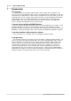
Contents I Table of Contents 1 Introduction 1 2 Installation 2 2.1 System Requirements ................................................................................................................................... 2 2.2 Software Installation ................................................................................................................................... 3 3 System Description 8 4 Getting Started 9 5 Main Menu 5.1 File Menu..........................................
1 1 GX Configurator-DP Introduction This manual... ...is a compact guide to using GX Configurator-DP software suitable both for beginners and experienced users upgrading from other systems. The manual includes explanations of the terms and structural concepts about the software and the configuration of an open network system. The manual provides a precise step-by-step description of how to use GX Configurator-DP including sample projects.
Installation 2 2 Installation Before You Begin Copyright Important Notice: This software is protected by copyright. By opening the distribution disks package you automatically accept terms and conditions of the license agreement. You are only permitted to make one single copy of the original distribution disks for your own backup and archiving purposes.
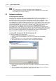
3 GX Configurator-DP Note: It is recommended to use Microsoft ® Windows 2000 or Windows XP. On all operating systems with the exception of Microsoft ® Windows XP, Microsoft ® Internet Explorer 5.5 must be installed. 2.2 Software Installation GX Configurator-DP Setup To install the GX Configurator-DP software from CD-ROM under Microsoft ® Windows 98/Windows Me or Windows NT/Windows 2000/Windows XP, you need to have Microsoft ® Windows installed properly.
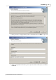
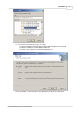
Installation 7. Enter your name, company and the product serial number. Click on Next > to proceed. 8. Check the registration information you have provided.
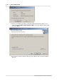
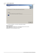
5 GX Configurator-DP 9. Enter the destination folder where you want the GX Configurator-DP software to be installed. (Default C:\Melsec\GX Configurator-DP ). If you agree with the default setting, just click on Next >. 10. If you want to install to a different directory click on Browse and select the installation directory.
Installation 11. You can choose between three types of setups: · Typical: installation of GX Configurator-DP and GX Configurator-ST (default) · Compact: installation of GX Configurator-DP only · Custom: select, whether to install GX Configurator-ST 12. The installation is started. Progress bars will inform you about the setup status.
7 GX Configurator-DP 13. After the installation, you will see an appropriate message. Button Functions With the Next button you will leave the current menu and enter the next menu. With the Back button you go to the previous window. Cancel button ends the installation procedure.
System Description 3 8 System Description System Concept GX Configurator-DP is the configuration tool for PROFIBUS interfaces in MITSUBISHI PLCs. It provides functions for defining a PROFIBUS network, validating the configuration and downloading it to the respective PLC module via a MITSUBISHI automation network. For remote access independent of the user platform a web server is included.
9 4 GX Configurator-DP Getting Started Below are the main steps, which are required to configure a PROFIBUS DP master module. The QJ71PB92V module is used as an example. Start GX Configurator DP 1. Start GX Configurator-DP via the shortcut in the Programs menu. The default is MELSOFT Application/GX Configurator DP/GX Configurator DP. Add GSD File 1. Select the item GSD Device-Database in the main menu Setup to open the GSD Database. 2. Click on to add the new GSD file to the database.
Getting Started 3. Select the GSD file, which should be added to the database, and confirm with . Start a New Project 1. In the main menu File select New to open a new project file. 2. Select the type of master module, which you want to configure.
11 GX Configurator-DP 3. When you have clicked on a new project file is opened in the graphical network editor showing the selected type of PROFIBUS master module. Add Slave to the Network 1. In the graphical network editor press the right mouse button to open the context menu. Select the menu item Insert DP-Slave from the context menu to add a slave.
Getting Started 12 2. The GSD device database dialog opens where you can select the slave module. Choose the Slave Device Group from the drop down list and select a slave module from the list of the available slave systems below. Then confirm your selection with . 3. The slave is added to master configuration. Select Slave modules and Set User Parameters 1. In the 'Slave Parameter Settings' dialog click on
13 GX Configurator-DP 2. Select the modules, which are installed in the slave device, in the left list and add them to the list of installed modules by pressing or . The sequence of modules in the 'Installed Modules' list must usually equal the sequence of modules within the slave device. To delete a module from this list, mark the entry and press . Configure Connection to PLC 1.
Getting Started 14 Download Configuration to Master 1. Select Online -> Transfer -> Download to Module in the main menu to download the configuration to the master module. Create POU 1. To create the program code for GX IEC Developer, which assists with access to PROFIBUS I/O select File -> Export -> POU for GX IEC Developer. 2. Select the path for the GID ASCII file.
15 GX Configurator-DP Import POU in GID 1. Start GX IEC Developer and open the project for the PLC, which accesses the PROFIBUS master module. 2. Import the ASCII file generated by GXDP.
Main Menu 5 16 Main Menu Starting GX Configurator-DP Select GX Configurator-DP from the Windows Start menu. The default shortcut is Start/Programs/MELSOFT Application/GX Configurator-DP Main menu The main menu offers the following pull-down menus. The menu items Online and Window are available only, if a project is open. The pull-down menus can be selected via mouse or keyboard.
17 5.1 GX Configurator-DP Command Description Transfer Setup Defining the network connection type (PC to PLC) MXChange MXChange support properties GSD GSD device database Help Getting context help Help Tool Getting help on items you click on About Displaying program information File Menu After having started the GX Configurator-DP software, this is the first menu to work with. With the help of this menu you can create a new or load an existing project.
Main Menu Command Description Change Master Type Changes the current project to a different type of master module. Print Prints the project. Page Setup Specifies the page layout and selects parameters for printouts. Recent Files Opens one of the latest used projects. Exit Ends GX Configurator-DP. Command New The menu command New is used to create a new project. Note: No default module type is selected. Choose the target PLC family and a supported module type before continuing.
19 GX Configurator-DP Here you edit the dedicated parameters for the selected network interface module in specific editors. At present the A(1S)J71PB92D, QJ71PB92D, QJ71PB93D, QJ71PB92V and FX3U-64DP-M PROFIBUS DP network interfaces are supported. The following parameters can be edited: · Master Settings · Bus Parameters · Slave Parameter Settings Command Open The menu command Open allows to open a project, which has previously been saved. This command uses the Windows dialog box for file open operation.
Main Menu 20 The Open dialog box lists only files of the following type: · *.DP2: project for a master module configuration · *.DPX: project for a QJ71PB93D slave module configuration The shortcuts defined by the Windows dialog box for file open are valid. Compatibility to Older Versions Open previous project files in GX Configurator-DP 7.01B according to the following table File type Software version *.dp2 ProfiMap 3.0 GX Configurator-DP 4.00 GX Configurator-DP 4.01A GX Configurator-DP 4.
21 GX Configurator-DP This menu command is used to save a modified project with a new assigned file name. This command uses the dialog box for file saving. The file extension *.DP2 or *.DPX is appended automatically depending on the module type you selected. Command Export This menu command opens another submenu in which the user can choose between generating PLC program code or saving the configuration image to file for a download to the master with a different tool.
Main Menu 22 For QJ71PB92D and QJ71PB92V master modules consistency can only be ensured, if autorefresh with consistency is used for data transfer between CPU and master. The A(1S)J71PB92D master maintains consistency in both A- and QnA-series systems. For A(1S)J71PB92D and QJ71PB92D in operating mode 0 no POU can be generated. Note: The ASCII file must be imported in GX IEC Developer. If a user library is referenced, it will automatically be imported as well.
23 GX Configurator-DP Note: The detailed I/O data structures for ST1H-PB slave modules are only available in the full version of the POU. The user can select the directory and the name of the POU ASCII file. The file name must start with a letter and not have more than 16 characters. The file name is used as name for user library and program as well. If a user library is generated as well, it is located in the same directory, but with the extension '.sul' instead of '.asc'. Additionally to the .
Main Menu 24 Command Change Master Type With this menu item the user can change the current project to a different operating mode or to a different type of master module. Command Print This command is available for master projects only. It creates an HTML document containing the settings of the current project and displays the document in the default web browser. Detailed appearance of the printout depends therefore on the browser.
25 GX Configurator-DP Command Page Setup Available for master projects only. When you choose Page Setup you can select the parameters to be printed. Additionally you can enter a descriptive header text and select the position of the header on the page: top or bottom. If you select No header the header information will not be printed. The settings including the header text are not stored in the project file, but locally on the PC and apply to all projects.
Main Menu 26 Command Recent Files The pull-down menu shows you the last four used projects. You can open one of them by pressing the shortcut 1 to 4 or selecting it using mouse or keyboard. Command Exit You can use this menu command to quit the software. If an open project has been modified and has not yet been saved the following message appears: If you want to save the last changes before leaving and terminating the GX Configurator-DP software choose .
27 GX Configurator-DP Command Purpose MXChange Support setup of the properties of the MXChange connection GSD Device Database access to the GSD device database PLC and GX IEC Developer (GID) Settings opens a dialog with tab pages, which allow to configure the data exchange between PROFIBUS master and PLC CPU Options opens a dialog in which the user can change settings related to the GSD database Command MXChange Support Available for *.DP2 projects only.
Main Menu Command Description Select Server Instance selects one of up to 16 available servers to connect to IP Address specifies the IP address of the MXChange server in LAN (ask your network administrator) enter your user name for the MXChange server enter your password for the MXChange server tests, if a connection to the MXChange server can be established with the specified settings User Name Password Test 28 You can set the MXChange connection usage for the A(1S)J71PB92D or QJ71PB92D project b
29 GX Configurator-DP When a group is selected in the box ”Slave Device Group”, the model names of the devices belonging to the selected group are displayed in the lower list box ”Available Slave Systems”. Upon selecting a device entry in this list box the bitmap, which has been assigned to the device, is displayed on the right side of the list box. By double-clicking on the bitmap display or using the button "Replace Bitmap", a file dialog is opened, in which a file with a new bitmap can be selected.
Main Menu File Extension 30 dib, bmp Only bitmaps that match the requirements in the table above should be used. Other bitmaps with other sizes and color depths can be used, but will cause a warning message When both GSD and bitmap file have been selected, you will be asked to confirm the operation. If you confirm, the contents of both files are read in and an entry is added to the internal device database for that device. Thereafter, you do not need the actual GSD and bitmap files any more.
31 GX Configurator-DP different to that of the existing device or choose to replace the existing entry. If you choose to replace the GSD file, internally the existing entry is deleted first and then the new GSD file is parsed. This will however not effect existing projects, which already use the device type and where the GSD information is part of the project file. Slave Device Group DP slaves are grouped in one of the so-called ‘slave families’. The default group is usually specified in the GSD file.
Main Menu 32 Removing devices A device can be removed from the database by selecting the entry in the left list box and pressing the button. This deletes only the entry in the GSD database. It does not delete the GSD and bitmap files for that device. These files have to be removed manually. Note: The entry is immediately removed after clicking on the button.
33 GX Configurator-DP Input Fields Description Slave Specific Transfer Buffer devices are assigned to each slave individually in the column "Buffer MIT-Address" in the "I/O Mapping" dialog. This option is only useful in combination with autorefresh or for the 'Copy POU' of the FX3U-64DP-M master. Block Transfer The input as well as the output areas of all slaves are transferred in a single step using one common transfer buffer.
Main Menu Input Fields Description AutoRefresh (Update of GID project) Use autorefresh and update the settings offline in the corresponding GID project or the selected autorefresh settings file (usually named 'iparam.wpa') 34 For transferring the slave I/O data, there is a choice of two different methods: Slave Specific Transfer: each input and output area of a slave can be mapped to a separate device address.
35 GX Configurator-DP By updating the GID project instead of the CPU directly it is ensured that the autorefresh settings for PROFIBUS are not accidentally deleted by a download of autorefresh settings from GID. Note: If the PROFIBUS master is located in a Q-series 'Remote I/O' rack, the option ' AutoRefresh (Update of GID Project)' must be selected. The selected GID project must be the one for the 'Remote I/O', not for the controlling CPU.
Main Menu 36 To apply the updated GSD database to an existing project the option GSD database has priority must be enabled. GSD database has priority This option controls, whether GSD information in the project file, if present, is overwritten by the corresponding information from the GSD database for the same types.
37 GX Configurator-DP default transfer setup is automatically added to the project file. With the button you can change the settings both for the default and for a new created transfer setup. For a more detailed description how to handle a transfer setup see also chapter Opening the transfer setup and defining a network connection. Command Transfer In the submenu Transfer the user can choose between: · Download to Module...
Main Menu 38 Download to project module type only GXDP will allow a download only to the same module type as specified in the project. If the module found in the specified slot of the target PLC rack does not match that of the project, an error message is displayed. If the user wants to download the project to a different module type, the project must first be converted to the type of the connected module. This is done by selecting the Change Master Type menu item.
39 GX Configurator-DP has been successfully downloaded to the PROFIBUS master module. AutoRefresh (Update of CPU) The (online) update of the autorefresh settings on the CPU is only possible, if the CPU is stopped. The CPU status is checked and, if the status is not 'Stopped', the user is asked, whether the CPU can be stopped. After stopping the CPU the autorefresh settings on the CPU are updated.
Main Menu 40 After a successful update, the path of the updated file is displayed. AutoRefresh Update of Q-series 'Remote I/O' CPU If the PROFIBUS master is located in the rack of a Q-series 'Remote I/O' CPU, the options 'AutoRefresh (Update of CPU)' and 'Copy Instructions' are not possible for data transfer. The user is informed and offered to update the autorefresh settings in a GID or GD project instead.
41 GX Configurator-DP configuration created from the current project. If both settings match, the following message box is displayed. If the settings differ, the following message box is displayed. More detailed information on which parts of the settings are different, is not provided. In case any problems occur, for example when reading the configuration from the module, a general error message is shown.
Main Menu 42 3. ‘Debug’ mode or only one PLC connected: only the master in the connected PLC is checked. Upload Config. Image GXDP tries to connect to a master module of the type set in the current project, using the selected transfer setup. If the connection is established, the current configuration is read from the master module and stored in binary format in the file, which the user has selected. Information stored in the PLC CPU like autorefresh settings or POU code is not retrieved.
43 5.4 GX Configurator-DP Tools Menu The Tools menu offers the following commands: Command Description Server Administrator starts a web server for online access to the modules. GX Configurator Client client for logging in to the web server for online access to the modules.
Main Menu Zoom Out 44 Decreases the view size of the graphical network editor. These menu commands allow you to select whether the tool bar and the status bar will be displayed or not. A check mark in front of the commands shows that this function is currently activated. Command Toolbar If the toolbar is enabled you will find additional buttons for creating documents, opening documents, saving documents or the help menu.
45 5.7 GX Configurator-DP Help Menu The Help menu offers the following commands, which provide you assistance with this application Command Purpose Index Offers you an index to topics on which you can get help. Using Help Provides general instructions on using help. About Displays the version number of this application. Command Index With the help of this function you can search for a keyword. Just type in the term you need information about and you will get help.
How to Create a New DP Master Project 6 46 How to Create a New DP Master Project Parameter Setting for PROFIBUS Master Modules Introduction and Overview This section describes how to generate the parameter settings for the A(1S)J71PB92D. Differences to the parameter setting for other PROFIBUS master modules are mentioned explicitly. After selecting the command New in the File menu choose the module type A(1S)J71PB92D.
47 GX Configurator-DP menu by pressing the right mouse button and select 'Insert DP-Slave'. The GSD database dialog is displayed and the type of the new slave device can be selected. After inserting the slave the dialog to adjust the slave parameter settings is displayed. The same dialog is displayed, if an existing slave is selected the item 'Modify Settings' is selected from the context menu.
How to Create a New DP Master Project 48 The field ‘Estimated bus cycle time’ shows the expected minimum interval between two I/O data exchanges with a slave.
49 GX Configurator-DP Parameter Meaning Error action flag Output processing after failure. Select this option, if you want to have the outputs shut off in case of error (recommended for drives, inverters etc.). In practice this means: After occurrence of any network error all outputs of the network are turned OFF and no diagnostic information from the slaves is returned. Autom.
How to Create a New DP Master Project 50 using a FROM/TO instruction and extending the cycle time. Automatic refresh is selected and cleared in the PLC Settings dialog. If either online update of the CPU or offline update of the GID project have been selected, the automatic refresh option in the Master Settings dialog is selected as well. The data areas included in autorefresh and the respective device addresses can be set in PLC and GX IEC Developer (GID) Settings.
51 GX Configurator-DP Parameter Description Baudrate Transfer rate (must be supported by all slaves) T_sl Slot time (max interval to wait for response) min T_sdr min station delay of responder max T_sdr max station delay of responder T_qui Quiet time T_set Setup time T_tr Target rotation time GAP factor controls the GAP update timer HSA highest station address Max retry limit max.
How to Create a New DP Master Project 52 When a model is selected and the button has been pressed, the Slave Parameter Settings dialog appears. Note: Adding a slave changes the addresses of the I/O data in the buffer memory of the master. It is therefore necessary to update the PLC program and (if used) the autorefresh settings. Duplicate Slave The configuration of a modular DP slave like the ST1H-PB involves several steps like selecting the modules and setting the module specific user parameters.
53 GX Configurator-DP Delete Slave In the graphical network editor select the slave module to be deleted and either: · press key or · Right-click on DP-Slave to open the context menu and select Delete DP-Slave Note: Deleting a slave changes the addresses of the I/O data in the buffer memory of the master. It is therefore necessary to update the PLC program and (if used) the autorefresh settings.
How to Create a New DP Master Project Item Description Name Name of the slave can be defined. This is for documentation purpose only. FDL Address Station address of the slave Watchdog When selected, the watchdog control of the slave is activated. The slave will check whether the master was in communication with the slave within the defined watchdog time. If there is no communication between slave and master within the specified watchdog time the outputs are turned to the safe state.
55 GX Configurator-DP DP V1/V2 Slave Parameters To access the DP V1/V2 slave parameters open the Slave Parameter Settings menu and click on the DP V1/V2 Slave Parameters button. The parameters have the following meaning: Item Description DP V1 support enabled Enable supported alarm types. Watchdog time base 1 ms The slave interprets the given value for watchdog time as a multiple of 1 ms instead of 10 ms. 'Fail Safe' function enabled The slave works in 'Fail Safe' mode.
How to Create a New DP Master Project 56 In case the slave supports the extended user parameter format click on button to access the following dialog box. The Extended User Parameters are not standardized but depend on the slave. The GSD file can provide descriptive texts for parameters as well as available settings. If these parameter descriptions are missing or incomplete the user parameters can also be changed within a simple hex editor.
57 GX Configurator-DP Be careful when editing these parameters via the hex editor. You should have a detailed slave documentation from the manufacturer to prevent errors. Note: These parameters should only be changed by experienced users. If no extended user parameter descriptions are available in the slave GSD file, this dialog is opened. Consult your slave device manufacturer to generate correct settings.
How to Create a New DP Master Project 58 The slave device is the summary of all modules installed in the slave. The GSD file includes all selectable modules for the slave device. Mark a module in the right list of Installed Modules. Then select a module in the left list of Available Modules and press the or button.
59 GX Configurator-DP When a Universal module entry in the Installed Module list is double-clicked, the Universal Module Settings dialog is opened and the properties of the selected universal module, i.e. consistency, input and output size, can be changed. If the module should only have an input area, select the option Inputs only and the field for the output length is hidden. If the module should only have an output area, select the option Outputs only and the field for the input length is hidden.
How to Create a New DP Master Project 1. The first module must be a head module. 2. Only one head module is possible.
61 GX Configurator-DP 3. The I/O size of all modules must fit within the buffer of the selected head module. GXDP checks these restrictions for the ST slave, when the user leaves the Slave Modules dialog via the button. If any of these restrictions are violated, an error message is displayed and the dialog remains open to allow the user to correct the selection. Project Transfer When the whole network creation is complete, the project should be saved with the help of the File menu.
Parameter Setting for QJ71PB93D Slave Modules 7 62 Parameter Setting for QJ71PB93D Slave Modules Introduction The QJ71PB93D module is a PROFIBUS DP V0 slave for System Q PLCs. It enables a DP master to access devices in a System Q CPU. The QJ71PB93D is configured partially by the DP master and by GX Configurator-DP. The project file for the QJ71PB93D slave module has the extension *.dpx (not *.dp2 as for PB92D master modules).
63 GX Configurator-DP Item Description FDL_address This item is used to define the station address of the slave. Autom. Refresh Enables Consistency function. See detailed description in chapter Autom. Refresh Input Size Specifies the size of the input area in units of words. Output Size Specifies the size of the output area in units of words. Input CPU Device Specifies the input device and its start address in the CPU.
I/O Mapping 8 64 I/O Mapping The purpose of I/O mapping is an easier access to the input and output data cyclically exchanged between the Profibus master and the connected slaves.
65 GX Configurator-DP The tree view displays the slaves and slave modules in the master configuration project with the following levels: Level Type Text 1 Master Type name 2 Slave FDL address, user assigned name and type name 3 Slave Module Type name of module Table View When a slave or a slave module is selected in the tree, the table lists the I/O areas of the respective slave or module. These are represented by elements of DUTs in the generated program code.
I/O Mapping 66 For standard slaves and modules the generated DUT contains one ARRAY OF WORD element for the input and one for the output area. The array size is determined by the I/O size of the slave or module, rounding an odd byte size up to the next word boundary. For the modules of ST1H-PB slaves the generated DUTs contain module specific elements for I/O data, control, status and error information. Item Description DUT Var.
67 GX Configurator-DP User MIT-Address The purpose of user devices is to access an I/O area via a fixed device address. The buffer device address of an I/O area should not be referenced by the PLC application program, because they change, when slaves and/or modules are added or removed. To assign a user device select the cell in the column ‘User MIT-Address’ and enter the device address. A list shows the available device types and maximum address ranges.
I/O Mapping (c) 2006 MITSUBISHI ELECTRIC CORPORATION 68
69 9 GX Configurator-DP Transfer Setup Introduction GX Configurator-DP is capable of downloading configuration data to the PROFIBUS master module via a variety of different communication types. The master module can be located in a PLC rack directly connected to the PC or in a PLC rack, which is connected to other PLCs in a separate network. Note: The transfer setup is only available in master projects, not in slave projects.
Transfer Setup 70 The CPU types are grouped in families. The available families depend on the type of the master module according to the table below. Master Module Type Available PLC Families A(1S)J71PB92D A- and QnA-series QJ71PB92D Q-, QnPH- and QnPRH-series QJ71PB92V Q-, QnPH- and QnPRH-series FX3U-64DP-M FX-Series If the user selects a different family, the list of CPU types is updated to match the selected family. The user can change the CPU type or just press button to accept it.
71 GX Configurator-DP Transfer Setup for QnPRH CPU (2) (c) 2006 MITSUBISHI ELECTRIC CORPORATION
Transfer Setup Transfer Setup for FX3U CPU (3) (c) 2006 MITSUBISHI ELECTRIC CORPORATION 72
73 GX Configurator-DP Transfer Setup for Q Remote I/O (4) No . Description PC side I/F Choose the I/F for the connection of the PC to the PLC. PLC side I/F Choose the unit to be connected with the personal computer. Other station Choose no network or one of the specified network types Network route Choose the network type, network No., station number and first I/O No. to be accessed. The setting items depend on the network type that has been set.
Transfer Setup 74 PLC direct coupled setting By clicking this button you change from Other station to the own station. Connection test Tests whether proper access can be made to the PLC set as the access target on the Connection Setup screen. If proper access can be made, the model name of the PLC as the access target appears in the CPU type field Target System Specifies the connection destination for redundant PLC systems: 1.
75 GX Configurator-DP Dialog Connection channel list No. Description Graphical image of the in selected network type. Listing of the possible network configurations for the selected PLC. Update Click this button to confirm the selected network configuration without closing the dialogue OK Confirm the set network configuration and close dialogue. Cancel Closes the dialogue without saving. When the button Update was clicked the dialogue is closed but the network configuration is already saved.
Transfer Setup 76 Security note Test the selected network configuration by clicking on the button Connection test. If the connection between the PC and the network is possible a positive note will be shown on the screen. If no connection is possible an error message is shown. In this case you have to check the cabling as well as the connection parameters set in the transfer setup and, if used, the respective PLC network modules. Close the dialog by clicking on OK.
77 GX Configurator-DP Dialog System image After leaving the dialog, the new transfer setup is added with a default name. The default name is constructed as ‘TransferSetup’, where is the sequential index of the setup. If this name is already used, is incremented, until the name is unique. Define a network name or just use the default transfer setup name. Note: The network name is used to identify the settings for one transfer path and must therefore be unique.
Transfer Setup 78 Before the setup is actually removed, the user is asked to confirm the operation. Command Apply Changes of the transfer setup name and/or the module slot are saved. You can change the symbolic name of any network connection. Select the network connection you want to change. Enter the new name in the Transfer Setup Names drop-down list and confirm with the button. Note: The length of the transfer setup name is limited to 32 characters.
79 GX Configurator-DP The symbolic name for the transfer setup has changed and can be selected from the Transfer Setup Names drop-down list. Command Test The configured transfer setup can be tested online. When the button is clicked, a connection to the master module is initiated in two steps using the configured communication interfaces and parameters 1. connect to the target PLC 2.
Transfer Setup If a module of the specified type is found, a confirmation message is displayed.
81 10 GX Configurator-DP Web-Based Online Access The Tools menu includes tools for web-based online access to the network interface modules. Via the online access configuration projects (*.dp2 for DP masters, *.dpx for DP V0 slaves) created by GX Configurator-DP can be transferred to the PLC. In addition several diagnostics and service functions are available. For this purpose a Server Administrator is supplied which starts a web server on the personal computer the PLC to be configured is connected to.
Web-Based Online Access 82 Supported platforms Editing master modules and PB93D configuration projects with the GX Configurator-DP software is supported on Microsoft Windows platforms only. Server: Microsoft Windows 98/ Windows Me, Windows NT, Windows 2000, Windows XP Microsoft Internet Explorer 5.
83 GX Configurator-DP · Ethernet link from PC to System Q-PLC and MELSECNET/10 to 2nd level System Q rack · Serial via MAC to A, QnA series, and System Q PLCs (transparent mode) Not supported are: · Ethernet and MELSECNET access to A series PLCs · Serial access to C24 modules · CC-link networks Note: For successful network settings you should be familiar with the characteristics of MELSEC Ethernet and MELSECNET/10 and refer to the corresponding manuals.
Web-Based Online Access 84 When the server is started, a separate console (DOS) window appears. This window should never be closed, as this will result in an improper termination of the server. The "Stop Server" function of the server administrator should be used instead. This will also close the console window, after the server has been shutdown.
85 GX Configurator-DP The file users is an ASCII file and can be edited with for example Microsoft Notepad. For each user there is a line in the file with the user name and the password separated by a colon (‘:’). Optionally the attribute ‘read+write’ can be added, separated from the password with another colon. This attribute means that the user has read and write access, i.e. he can download a PROFIBUS configuration or start/stop the CPU.
Web-Based Online Access 86 Connect Connect to the selected target PLC to be configured. Browse Browse for network configuration files (*.xml) to be uploaded to the web server. Upload Upload the browsed network configuration file (*.xml) to the web server to be added to the network database. Network Configuration File Location of Configuration Files The GXDP webserver loads the configuration of PLC connections from XML files in the subdirectory ‘Server\gxmonitor\WebApps\config‘.
87 GX Configurator-DP Figure 1The XML network path resembles the actual network architecture The network path is described by listing the connected components, i. e. the communication interface on the PC side (XML node ) and in the PLC (XML node ). A network path definition must always contain a node 'PCNode' and one or two nodes of type 'PLCModule'. Network Path Samples PC accesses MELSECNET via Serial Port In this combination a PLC is connected to the PC via a serial link.
Web-Based Online Access 88 PC accesses MELSECNET via Ethernet In this combination a PLC is connected to the PC via ethernet. The PC must therefore know the IP address of the E71 board in the PLC rack. Connection to the E71 can be tested with the 'ping ...' command, where the parameter is the IP address, which has been set in the network parameters using either GX Developer or GX IEC Developer.
89 GX Configurator-DP Module Name (underlined) Opens the web page Module Configuration for a PROFIBUS master (see below) or for a PROFIBUS slave (see below). CPU Mode Displays the current CPU mode. The desired CPU mode can be selected from the drop down list and set via the button. Current Autorefresh Settings Open the Auto Refresh Settings page.
Web-Based Online Access 90 Mode Displays the current operating mode of the module. The desired operating mode can be selected from the drop down list and set via the Set button. Note: The current FDL address cannot be displayed for the A(1S)J71PB92D. If you use a A(1S)J71PB92D module the user must set the correct mode with the switch on the front of the module. The modes are 0 or E for operation mode and 1 for configuration mode. The module will take over the setting of the mode switch after a CPU reset.
91 GX Configurator-DP client computer. The Write to PLC button uploads the selected configuration project to the web server where it is written to the PLC. Note: By downloading a configuration you stop the data exchange on the DP network. If the configuration download is successful, the following web page appears: Update Autorefresh in CPU: Only available for Q series, and only if the CPU is stopped.
Web-Based Online Access 92 Slave List Opens the web page Slave List (see below) Current Configuration Opens the web page Current Module Settings (see below) Save Configuration Saves the current module settings in an XML-format file with the default extension *.gxdp. This function is intended for documentation purposes only. The saved XML-format file does not contain the full contents of a configuration project file but only the information that is actually on the module.
93 GX Configurator-DP Note: At this page the information of all installed modules are displayed. Slave List This web page shows status information on the DP slaves connected to the DP master. Current Module Settings This web page shows the current configuration of the DP master module previously selected.
Web-Based Online Access 94 Module Configuration This web page shows the current configuration of the PB93D DP slave module previously selected. Mode Displays the current operating mode of the module. The desired operating mode can be selected from the drop down list and set via the Set button. · Mode 0: Normal operation mode. Allows upload and download of configuration. · Mode 2: Diagnostic mode. Project To configure the DP slave a configuration project (*.dpx) created by GX Configurator-DP is required.
95 GX Configurator-DP CPU are updated immediately after successfully writing the configuration project to the PLC. If an autorefresh entry for this slot is already present in the IPARAM file, it is overwritten with the settings matching the module configuration. If no IPARAM file is found, it is created. If no entry for this slot can be found, it is inserted at the appropriate position in the file.
Troubleshooting 11 96 Troubleshooting Web Browser Related Hints Problem 1 Your web browser can not access the GX Configurator-DP web server running on your local computer or in your local network. Solution In case you use a proxy server for the connection of your intranet (LAN) to the Internet ensure that your web browser bypasses this proxy server for local connections.
97 GX Configurator-DP Problem 1: Your web browser cannot connect to the web server computer via the Server Computer Name displayed in the GX Configurator-DP Server Administrator. Solution The Server Computer Name (i.e. DNS Host Name) cannot be resolved by a DNS server. Microsoft Windows computers have a computer name entered when installing the operating system, which can also be changed afterwards. This is the "NetBIOS name". Usually this name is the only name of this computer across a network.
Troubleshooting 98 In the TCP/IP Properties dialog under the DNS tab we enter the new DNS Host Name "hugo" in the Host Name field. This name is not registered on a DNS server.
99 GX Configurator-DP When the DNS Host Name (here: "hugo") and the NetBIOS name (here: "derry") differ, GX Configurator-DP displays the following message box: When you use the DNS Host Name on another (client) computer as communication target the other computer will try to get the IP address from a DNS server. If the target computer is not found by its DNS Host Name, it is not possible to communicate with it.
Index M Table of Contents F File menu Change Master Type 24 Close 20 Configuration Image 23 Exit 26 Export 21 New 18 Open 19 Page Setup 25 POU for GX IEC Developer Print 24 Recent Files 26 Save 20 Save as 20 100 Menus Toolbar Items 16 O Online menu Download Config.Image 42 Download to Module... 37 Start/Stop PROFIBUS 42 Transfer 37 Transfer Setup 36 Upload Config.Image 42 Verify 40 21 P Parameter Setting for QJ71PB93D Slave Modules Automatic Refresh 63 Consistency 63 H S Help menu About...
101 GX Configurator-DP Troubleshooting Web browser related hints 96 V View menu Status bar 44 Toolbar 44 Zoom In 44 Zoom Out 44 W Window menu 1,2,3,...
MITSUBISHI ELECTRIC