• SAFETY PRECAUTIONS • (Read these precautions before using this product.) Before using this product, please read this manual and the relevant manuals carefully and pay full attention to safety to handle the product correctly. The precautions given in this manual are concerned with this product only. For the safety precautions of the programmable controller system, refer to the user's manual for the CPU module User’s Manual.
• CONDITIONS OF USE FOR THE PRODUCT • (1) Mitsubishi programmable controller ("the PRODUCT") shall be used in conditions; i) where any problem, fault or failure occurring in the PRODUCT, if any, shall not lead to any major or serious accident; and ii) where the backup and fail-safe function are systematically or automatically provided outside of the PRODUCT for the case of any problem, fault or failure occurring in the PRODUCT.
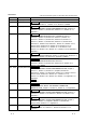
REVISIONS * The manual number is given on the bottom left of the back cover. Print Date Jun., 2001 Sep., 2001 Feb., 2002 Aug., 2002 Feb., 2003 May., 2004 Mar., 2005 May, 2007 Jan., 2008 Apr., 2008 Oct., 2008 A-3 * Manual Number Revision SH (NA)-080172-A First edition SH (NA)-080172-B Modifications CONTENTS, Section 4.1.1, Section 4.1.2, Section 4.2, INDEX SH (NA)-080172-C Modifications ABOUT THE GENERIC TERMS AND ABBREVIATIONS, Section 2.2, Section 3.2, Section 5.1, Section 8.2, Section 11.1.
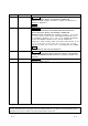
Print Date Mar., 2009 Apr., 2010 Apr., 2011 May, 2012 * Manual Number Revision SH (NA)-080172-L Modifications ABOUT MANUALS, ABOUT THE GENERIC TERMS AND ABBREVIATIONS, Chapter 1, Section 2.1, Section 2.3, Section 4.1.2, Section 7.1, Appendix 3 Addition Section 7.1.1 SH (NA)-080172-M Modifications SAFETY PRECAUTIONS, SOFTWARE USER REGISTRATION, ABOUT MANUALS, ABOUT THE GENERIC TERMS AND ABBREVIATIONS, PACKING LIST, Chapter 1, Section 1.1, 2.1, 2.2, 2.3, 3.1, 4.1.2, 4.1.3, 4.1.4, 4.2, 4.3, 5.1, 5.
INTRODUCTION Thank you for choosing the Mitsubishi MELSOFT Series Integrated FA software. Read this manual and make sure you understand the functions and performance of MELSOFT series thoroughly in advance to ensure correct use. CONTENTS SAFETY PRECAUTIONS..............................................................................................................................A- 1 CONDITIONS OF USE FOR THE PRODUCT ...........................................................................................
6. PROJECT CREATION 6- 1 to 6-18 6.1 Creating a New Project ............................................................................................................................ 6- 2 6.2 Opening the Existing Project ................................................................................................................... 6- 6 6.3 Saving the Project .................................................................................................................................... 6- 8 6.
10.3 Sampling Monitor ................................................................................................................................. 10-25 10.3.1 Sampling signal monitor................................................................................................................ 10-25 10.3.2 Sampling buffer monitor................................................................................................................ 10-27 10.4 Test...............................................
ABOUT MANUALS The following manuals are related to this product. Refer to the following table and request the required ones. Related Manuals Manual Number (Model Code) Manual Name Type QD75P/QD75D Positioning Module User's Manual Describes the system configuration, performance specifications, functions, handling, pre-operation procedures and troubleshooting of the QD75P1/QD75P2/QD75P4 and QD75D1/QD75D2/QD75D4.
HOW TO USE THIS MANUAL BASIC OPERATION PURPOSE Operation to be performed until the actual operation screen appears. Purpose of operation explained in each chapter, section or paragraph. 8.3.2 M code comment PURPOSE Set comments to M codes which are required for control exercised in synchronization with positioning. M code comments are data which can be saved only on the peripheral device. Up to 50 comments can be set for each axis. BASIC OPERATION 1.
In addition, there are also the following explanations. HELPFUL OPERATION Describes application operation if there are multiple purposes and the basic operation and display/setting data do not provide enough information. HELPFUL CORRECTIVE ACTIONS Explains corrective actions if monitored data is abnormal or a test cannot be made. Provides information relevant to that page, e.g. the items you should be careful of and the functions you should know.
ABOUT THE GENERIC TERMS AND ABBREVIATIONS The following generic terms and abbreviations for the software for positioning module, positioning modules, etc. are used in this manual.
Generic Term/Abbreviation Multiple-license product Update-only product Windows 7 R Description Abbreviation for multiple-license product of GX Configurator-QP Abbreviation for update-only product of GX Configurator-QP Generic term for the following: Microsoft Windows 7 Starter Operating System, Microsoft Windows 7 Home Premium Operating System, Microsoft Windows 7 Professional Operating System, Microsoft Windows 7 Ultimate Operating System, Microsoft Windows 7 Enterprise Operating System Note that the 32-
1. OVERVIEW MELSOFT 1. OVERVIEW This manual describes the functions and operating procedures of GX Configurator-QP. GX Configurator-QP is a software package that performs various functions such as data settings, monitoring, and tests for the MELSEC-Q/L series positioning modules. GX Configurator-QP offers the following functions.
1. OVERVIEW MELSOFT GX Configurator-QP can access the LD75/LD77 via any of the following modules. 1 Module type LCPU L corresponding serial communication module Model L02CPU, L26CPU-BT LJ71C24, LJ71C24-R2 GX Configurator-QP can simultaneously edit positioning module projects of MELSEC-Q series and MELSEC-L series. Also, online operation in each project is available by specifying a connection target for each project.
1. OVERVIEW MELSOFT 1.1 Features (1) Concurrent editing of multiple projects Capable of opening multiple projects simultaneously, this software allows you to easily edit the positioning data and block start data to be utilized by copying and pasting. Copy & paste (2) Efficient debugging of multi-modules Because the QD75/LD75/LD77 to be connected to is set per project, batch write to or monitoring of multi-modules can be performed.
1. OVERVIEW MELSOFT (3) Simplified program by auto refresh setting Auto refresh setting is made to automatically read the following values stored in QD75/LD75/LD77 buffer memory to the QCPU/LCPU devices. • Feed present value • Machine feed value • Feed speed • Error No. • Warning No. • Enable M code Auto refresh setting reduces the number of FROM instructions used to read the buffer memory storage values, facilitating creation and debugging of programs.
1. OVERVIEW MELSOFT (5) Setting of optimum positioning data without complicated calculation Positioning data can be set by sub arc setting and automatic axis speed setting. Sub arc setting generates from the specified two linear interpolation control data the circular interpolation control data in which the angle between two linear paths is converted into a circular arc (curve) path.
1. OVERVIEW MELSOFT (8) Compatible with multiple CPU system (only for QD75) On GX Configurator-QP, setting the control CPU type and PLC No. of the QD75 to communicate with in Connection Setup (refer to Section 7.1) allows communication to be made with any QD75. PLC PLC PLC PLC No. 1 No. 2 No. 3 No. 4 QCPU QCPU QCPU QCPU QD75 QD75 QD75 1 2 3 PLC No. of control CPU In Connection Setup, specify the control CPU type and PLC No. of the QD75 to communicate with.
1. OVERVIEW MELSOFT 1.2 Manual Makeup This manual is made up of 11 chapters and appendices. This manual assumes that GX Configurator-QP is used to perform steps from positioning control system checking to operation in the following procedure. Step 1: Install and wire the positioning control system.
1. OVERVIEW MELSOFT (From the preceding page) Step 5: Set and write data to the positioning module. Refer To • Set the parameters appropriate for the positioning control system and control. • Set the servo parameters appropriate for the specifications of the servo amplifiers and motors used. (Only QD75M, QD75MH, and LD77) • Set the positioning data and M code comments. • Check the positioning data on the simulation screen.
2. SYSTEM CONFIGURATION MELSOFT 2. SYSTEM CONFIGURATION 2.
2.
2.
2.
2.
2. SYSTEM CONFIGURATION MELSOFT • Do not connect a peripheral device to the serial communication module by multidrop link. • When the GOT transparent mode is activated, Ethernet connection cannot be made between GOT and a peripheral device and between GOT and the programmable controller.
2. SYSTEM CONFIGURATION MELSOFT (3) About the connection cables (a) Connection to QCPU or Q corresponding MELSECNET/H network remote I/O module by QC30R2 (made by Mitsubishi Electric) When the baudrate is set to 115.2/57.6kbps, communication cannot be made unless the peripheral device used is compatible with the communication speed of 115.2/57.6kbps. If a communication error occurs, reduce the baudrate setting and restart communication.
2. SYSTEM CONFIGURATION MELSOFT (d) Connection to serial communication module The specifications of the RS-232 cable connector are indicated below.
2. SYSTEM CONFIGURATION MELSOFT 2.2 Operating Environment The operating environment of GX Configurator-QP is indicated below. Item Peripheral device Description Personal computer PC CPU module Personal computer on which Windows R operates. MELSEC-Q series compatible PC CPU module (CONTEC CO., LTD. make) Computer main unit CPU Refer to the following table "Used operating system and performance required for Required personal computer".
2. SYSTEM CONFIGURATION MELSOFT Used operating system and performance required for personal computer Performance Required for Personal Computer Operating system Windows R 95 Windows R Windows R CPU Required memory Pentium R 133MHz or more 64MB or more 98 Pentium R 133MHz or more 64MB or more Me Pentium R 150MHz or more 64MB or more Workstation 4.
2. SYSTEM CONFIGURATION MELSOFT 2.3 Instructions for use of older version of GX Configurator-QP If using an older version of GX Configurator-QP, pay attention to the following. (1) For using QD75M • When GX Configurator-QP Version 2.13P or later is used, setting items and setting values for the QD75M parameters have been added. • If a QD75M project created with GX Configurator-QP Version 2.13P or later is opened on GX Configurator-QP Version 2.12N or earlier, some data will not be processed properly.
3. FUNCTION LIST MELSOFT 3. FUNCTION LIST 3.1 Function List (1) Function list The main functions of GX Configurator-QP are listed. Function 3 Edit Description QD75P/ QD75M/ QD75D QD75MH LD75 LD77 Sets the basic parameters #1, basic parameters #2, extended parameters #1, extended parameters #2, Parameter setting OPR basic parameters and OPR extended parameters. Sets the servo parameters. Sets servo basic parameters, servo regulation parameters and servo extended parameters for QD75M.
3. FUNCTION LIST Function MELSOFT Description QD75P/ QD75M/ QD75D QD75MH LD75 LD77 Enters the monitor mode from the positioning data edit window and monitors the positioning data during operation. Enters the monitor mode from the block start data edit window and monitors the block start Block start monitor data during operation. Monitors the operating states, such as feed present values, axis feed speeds, axis statuses Operation monitor and executed positioning data numbers, of all axes.
3. FUNCTION LIST Function Diagnosis Checking connect MELSOFT Description Traces the speed command for a given time and displays the waveform data relative to the time axis. Location trace Traces the position command or real value for a given time and displays the track data of the axes. Auto refresh setting Assigns the QD75/LD75/LD77 buffer memory and CPU module devices for auto refresh between QD75/LD75/LD77 and CPU module.
3. FUNCTION LIST MELSOFT 3.2 Menu List The menu bar drop-down menus are listed below.
4. INSTALLATION AND UNINSTALLATION MELSOFT 4. INSTALLATION AND UNINSTALLATION This chapter describes how to install and uninstall GX Configurator-QP. 4.1 Installation 4.1.1 Installation procedure New installation Install GX Configurator-QP. Register the name and company. Register the product ID. 4 Start GX Configurator-QP. Check whether installation has been completed properly. Installation procedure Refer to Section 4.1.2. Refer to Section 4.3.
4. INSTALLATION AND UNINSTALLATION MELSOFT 4.1.2 Installing GX Configurator-QP The following explains how to install GX Configurator-QP. • Before starting installation, close all other applications running on Windows . • Install GX Configurator-QP compatible with the operating system. For compatible GX Configurator-QP versions, refer to Appendix 3.
4. INSTALLATION AND UNINSTALLATION MELSOFT 1) After powering on the personal computer, start Windows . 2) Start Windows Explorer and click the drive where the disk is inserted. Double-click "Setup.exe". To display Windows Explorer, choose [Start] [Programs] [Windows Explorer]. : When user account control is enabled, the following dialog box appears. Click "Allow" or Yes button.
4. INSTALLATION AND UNINSTALLATION MELSOFT (From the preceding page) 3) If the message shown on the left appears, click the OK button, uninstall GX Configurator-QP, and then reinstall it. 4) If either of the left screens appears, perform operation in accordance with the instructions given in (a) in "(reference) When message appears at start of installation". After the operation is over, restart installation operation.
4. INSTALLATION AND UNINSTALLATION MELSOFT (From the preceding page) 7) Enter the name and company, and click the Next> button. 8) Check the registered name and company. If they are correct, click the Yes button. To change them, click the No button to return to the previous screen. 9) Enter the product ID and chick the Next> button. The product ID is given in the "License agreement" packed with the product. Proceed to Step 11) to install the product newly. Proceed to Step 10) to update the product.
4. INSTALLATION AND UNINSTALLATION MELSOFT (From the preceding page) 10) When an update-only product is used for updating, the screen shown on the left appears. Enter the product ID of the old product and click the Next> button. The product ID is given in the "Software Registration Card" or "License agreement" packed with the product. The screen shown on the left does not appear when the product is installed anew. 11) Specify the installation destination folder.
4. INSTALLATION AND UNINSTALLATION MELSOFT (From the preceding page) [Windows XP] The following screen may appear at installation. Click Continue . We checked operations in Windows XP (Problems never occur after installation.) The following screen may appear behind another screen. Then, press the Alt + Tab keys to bring it to the front.
4. INSTALLATION AND UNINSTALLATION MELSOFT (From the preceding page) [Windows Vista and Windows 7] The following screen may appear at installation. Click Install . (Although the displayed screen may differ for some operating systems, the operation is the same.) The following screen may appear behind another screen. Then, press the Alt + Tab keys to bring it to the front.
4. INSTALLATION AND UNINSTALLATION MELSOFT (From the preceding page) 12) When the screen on the left appears, installation is complete. Click the OK button. : When the following screen appears, select "This program installed correctly". Do not choose "Reinstall using recommended settings", because the installer installs an incorrect module. If choose, reinstall GX Configurator-QP with following POINT on the next page. 13) If the message shown on the left appears, restart Windows .
4. INSTALLATION AND UNINSTALLATION MELSOFT REMARK For Windows XP, Windows Vista , and Windows 7, the icon is registered under [MELSOFT Application], displayed by selecting [All Programs] from the start menu. R R R Note the following when starting the installer from the hard disk on the personal computer. If the "Program Compatibility Assistant" screen appears after the installation, choose "This program installed correctly".
4. INSTALLATION AND UNINSTALLATION MELSOFT (a) Installation of dcom95.exe or Axdist.exe Execute dcom95.exe or Axdist.exe provided for GX Configurator-QP. Install GX Configurator-QP after executing the exe file and restarting the IBM-PC/AT compatible. The exe file to be executed on the corresponding operating system is indicated below. Operating System File name Microsoft Windows 95 Operating System dcom95.exe Microsoft Windows 98 Operating System Axdist.
4. INSTALLATION AND UNINSTALLATION MELSOFT 4.1.3 Installing the USB Driver To communicate between the personal computer on which Windows 2000 Professional, Windows XP, Windows Vista , or Windows 7 has been installed and the CPU module with USB, install a USB driver. The following is the USB driver installation procedure. R R R R If the USB driver cannot be installed, check the following setting.
4. INSTALLATION AND UNINSTALLATION MELSOFT (From the previous page) 2) Choose " Search for a suitable driver for my device (recommended)" and click the Next> . 3) Check "Specify a location" and click the Next> . 4) As the screen on the left appears, set the GX ConfiguratorQP installation destination "Easysocket\USBdrivers" and click the Next> . The screen shown on the left shows the example of setting C:\MELSEC\Easysocket\USBdrivers.
4. INSTALLATION AND UNINSTALLATION MELSOFT [2] When Windows XP is used R The following indicates the procedure for installing the USB driver when using Windows XP. R 1) The screen shown on the left appears when the personal computer and the CPU module is connected with USB cable. Choose "Install from a list or specific location [Advanced]" and click the Next> . 2) As the screen on the left appears, choose "Include this location in the search".
4. INSTALLATION AND UNINSTALLATION MELSOFT (From the previous page) 4) The screen on the left appears to indicate completion of installation. Click the Finish to terminate installation.
4. INSTALLATION AND UNINSTALLATION MELSOFT [3] When Windows Vista is used R The following shows installation procedure of USB driver when using Windows Vista . R 1) The screen shown on the left appears when the personal computer and the CPU module is connected with USB cable. Choose "Locate and install driver software (recommended)" and wait until searching ends. : When user account control is enabled, the following screen appears. Click the Continue button. 2) The left screen appears.
4. INSTALLATION AND UNINSTALLATION MELSOFT (From the previous page) 4) The left screen appears. Select "Install this driver software anyway". 5) The left screen appears. Click the Close button. 6) The left screen appears when the installation is completed. Click the Close button to exit.
4. INSTALLATION AND UNINSTALLATION MELSOFT [4] When Windows 7 is used R The following shows installation procedure of USB driver when using Windows 7. R 1) The message shown on the left appears when the personal computer is connected to the CPU module with a USB cable. 2) Select "System and Security" from the Control Panel. To display the Control Panel, select [Start] - [Control Panel]. 3) The screen shown on the left appears. Select "Administrative Tools". 4) The screen shown on the left appears.
4. INSTALLATION AND UNINSTALLATION MELSOFT (From the previous page) 5) Right-click "Unknown device" in the Windows Device Manager as shown left, and select "Update Driver Software…". REMARKS If multiple 'Unknown devices' exist therefore cannot be specified, right-click "Unknown device" as shown left and select "Properties". The "Unknown device", whose "Hardware Ids" is "USB\VID_06D3&PID_1800" on the <> tab of the properties screen, is the update target. 6) The screen shown on the left appears.
4. INSTALLATION AND UNINSTALLATION MELSOFT (From the previous page) 7) The screen shown on the left appears. Set installation location of GX Configurator-QP, "Easysocket\USBdrivers". Then, click the Next> button. The left screen is an example when C:\MELSEC\Easysocket\USBdrivers is set. If multiple MELSOFT products have been installed, refer to the installation location of the first installed product. 8) The screen shown on the left appears. Click the Install button.
4. INSTALLATION AND UNINSTALLATION MELSOFT 4.1.4 Upgrading the USB drivers In Windows Vista or Windows 7, if MELSOFT incompatible with each operating system has been installed when MELSOFT compatible with each operating system is installed, upgrading the USB drivers is required. R R The USB driver has the following two types: x USB driver for CPU module connection x USB driver for GOT connection (used for the GOT transparent mode.
4. INSTALLATION AND UNINSTALLATION MELSOFT (From the previous page) 3) The warning dialog box shown on the left appears. Select "Delete the driver software for this device." and click the OK button. 4) Disconnect the USB cable and reconnect it to the same USB port after 5 seconds. [Windows Vista ] The confirmation dialog box the following screen appears. Select "Ask me again later". R [Windows 7] The following balloon appears for a little while.
4. INSTALLATION AND UNINSTALLATION MELSOFT (From the previous page) 5) Right-click "Unknown device" in the Windows Device Manager and select "Update Driver Software…". REMARKS If there are several unknown devices and a driver to be upgraded cannot be specified, right-click "Unknown device" and select "Properties". The "Unknown device", whose "Hardware Ids" is "USB\VID_06D3&PID_1800" in the "Details" tab of the "Unknown device Properties" dialog box, is the upgrade target.
4. INSTALLATION AND UNINSTALLATION MELSOFT (From the previous page) 7) The dialog box shown on the left appears. Set the installation location of this product, "Easysocket\USBdrivers" and click Next . The left dialog box shows an example when "C:\MELSEC\Easysocket\USBdrivers" is set. When multiple MELSOFT products have been installed, set the installation location of the first-installed product.
4. INSTALLATION AND UNINSTALLATION MELSOFT (From the previous page) 9) The confirmation dialog box shown on the left appears. Select Close . Upgrade is completed.
4. INSTALLATION AND UNINSTALLATION MELSOFT (2) Procedure for upgrading the USB driver for GOT connection (a) Check method While the personal computer is connected to GOT with USB, power off and then on the GOT and then start the Windows Device Manager. If "MITSUBISHI GOT1000 USB Controller" is not displayed under "Universal Serial Bus controllers", and "Unknown device" is displayed under "Other devices", the driver needs to be upgraded.
4. INSTALLATION AND UNINSTALLATION MELSOFT (From the previous page) 3) The confirmation dialog box shown on the left appears. Select "Browse my computer for driver software". 4) The dialog box shown on the left appears. Set the installation location of this product, "EZSocket\EZSocketGOT\Drivers" and click Next . The left dialog box shows an example when "C:\MELSEC\EZSocket\EZSocketGOT\Drivers" is set.
4. INSTALLATION AND UNINSTALLATION MELSOFT 4.2 Uninstallation This section explains the operation for removing GX Configurator-QP from the hard disk. Displayed screens may differ depending on the operating system. In such a case, uninstall GX Configurator-QP with referring to "Remarks". (1) Uninstalling GX Configurator-QP 1) Double-click "Add/Remove Programs" on the Control Panel. To display the Control Panel, choose [Start] [Settings] [Control Panel].
4. INSTALLATION AND UNINSTALLATION MELSOFT 2) Choose "GX Configurator-QP". After selection, click Add/Remove . REMARKS The screen shown on the left is the one for Windows 98. The displayed screen varies with the operating system. Depending on the used operating system, perform the following operation. R R (a) Click "Add/Remove Programs". (b) Choose "GX Configurator-QP". (c) Click the Change/Remove button.
4. INSTALLATION AND UNINSTALLATION MELSOFT (From the preceding page) 3) Confirm that the file may be removed. Clicking the Yes button starts uninstallation. Clicking the No button stops uninstallation. 4) If the left screen has appeared, click the No To All button. If you click the Yes or Yes To All button, the shared file of the Windows compatible MELSOFT software is removed. Therefore, click the No To All button when removing GX Configurator-QP only.
4. INSTALLATION AND UNINSTALLATION MELSOFT 4.3 Starting GX Configurator-QP This section explains how to start GX Configurator-QP from the start menu. 1) Move the cursor from [Start] [MELSOFT Application]. [Programs ] : [All Programs] is shown for Windows Windows Vista , and Windows 7. R R XP, R 2) Click [GX Configurator-QP]. 3) GX Configurator-QP starts.
4. INSTALLATION AND UNINSTALLATION MELSOFT 4.4 Exiting GX Configurator-QP This section describes how to exit GX Configurator-QP. (1) Menu-driven exit method Click the [Project] [Exit] menu. GX Configurator-QP ends. (2) Title bar-driven exit method and choose [Close]. Click Alternatively, click at the right end of the title bar. In the online status such as the monitor or test mode, you cannot exit GX Configurator-QP. In any of the following cases, end the program after choosing the offline status.
4.
5. SCREEN MAKEUP AND BASIC OPERATIONS MELSOFT 5. SCREEN MAKEUP AND BASIC OPERATIONS This chapter explains the screen makeup and the display selection, window arrangement and other operations of GX Configurator-QP. 5.1 Screen Makeup and Display Selection Title bar This section provides the screen makeup of GX Configurator-QP. Menu bar Screen minimize button Toolbar Drop-down menu Online toolbar Screen maximize button Exits GX Configurator-QP.
5. SCREEN MAKEUP AND BASIC OPERATIONS MELSOFT 5.2 Basic Operations (1) Basic operation for project tree view (a) Opening a window The currently open project appears on the project tree view. Double-click the project name or click to show its functions. (From the keyboard, choose the project name and press the " " key.) Double-click the function name or click to show the window types. (From the keyboard, choose the function name and press the " " key.) Double-click the window name to open that window.
5. SCREEN MAKEUP AND BASIC OPERATIONS MELSOFT (2) Basic operation for dialog boxes 1) Tab 2) Text box 3) Command button 4) Radio button 5) List box 6) Check box 1) Tab Click the setting item name to select. 2) Text box Type numerals/characters. 3) Command button Click this button when executing "OK", "Cancel" etc., or when displaying the dialog box. 4) Radio button Click to choose one item among multiple choices. 5) List box Click to list choices, then click the item to be chosen.
5. SCREEN MAKEUP AND BASIC OPERATIONS MELSOFT (3) Moving the focus from the keyboard Use the "Alt" key to move the focus to the drop-down menu. Use the "F6" key to move the focus between the project tree view and window (edit, monitor, trace, checking connect). (4) Shortcut key list The following shortcut keys can be used with GX Configurator-QP.
6. PROJECT CREATION MELSOFT 6. PROJECT CREATION A project is a collection of parameters, servo parameters, positioning data and block start data. 6 When executing "New Project" or "Save as Project", you cannot use the following characters and symbols in the project path and project name to be specified.
6. PROJECT CREATION MELSOFT 6.1 Creating a New Project Set the QD75/LD75/LD77 model used to create a new project and the project items. 1) Click the [Project] [New Project] menu ( ). 2) Click the "Reference" button of the Module type in the [New Project] dialog box. 3) Choose the Select type and Select Axis radio buttons. 6 4) Click the "OK" button.
6. PROJECT CREATION (From the preceding page) MELSOFT 5) Set the project save path. The project save path defaults to C:\MELSEC\QD75P. When changing it, refer to "HELPFUL OPERATION (PART 1)" in this section. 6) Set the project name. When specifying the project file name, you can use a total of up to 150 characters to set the project path and project name. When setting the project path and project name, the total number of characters should be within 150.
6. PROJECT CREATION MELSOFT HELPFUL OPERATION (PART 1) You can perform the operation of changing the project save path while simultaneously checking the project tree view. In step 5) on the preceding page, click the Project file set "Reference" button. When the following dialog box appears, choose the project save path from the project tree view or type it from the keyboard. This operation is also used to perform such operations as "Open Project", "Save Project" and "Delete Project". 1) Choose the drive.
6. PROJECT CREATION MELSOFT HELPFUL OPERATION (PART 2) When utilizing the data written to the QD75/LD75/LD77 to create a new project, perform the following operation. 1. Set the Module type, project save path, project name and project title in the New Project dialog box. 2. Click the "New Project read to module" check box. 3. Click the "OK" button. 4. Click the "OK" button in the instruction dialog box. 5. Set the interface, I/O address and others in the Connection setup dialog box (refer to Section 7.1).
6. PROJECT CREATION MELSOFT 6.2 Opening the Existing Project This section explains the operation of opening the saved project. 1) Click the [Project] [Open Project] menu ( ). 2) Click the project name. For the setting operation of referring to the project save path, refer to "HELPFUL OPERATION (PART 1)" in Section 6.1. 3) Click the "Open" button. 4) The specified project opens. 5) To open multiple projects, repeat the operations in steps 1) to 3).
6. PROJECT CREATION MELSOFT • Projects created with GX Configurator-QP Version 2.33K or later cannot be opened with GX Configurator-QP Version 2.32J or earlier. Install GX Configurator-QP of the latest version. • Recently opened projects (files) can be opened from the project menu Up to four projects can be displayed. Note that any projects not saved do not remain in the project menu. In the initial setting, the [Latest file] menu item appears.
6. PROJECT CREATION MELSOFT 6.3 Saving the Project PURPOSE The project file which is currently edited is saved. BASIC OPERATION 1. Set the project to be saved as the active project. (Refer to Section 5.2.) ). 2. To perform save operation, click the [Project] [Save Project] menu ( To perform save as operation, click the [Project] [Save as Project] menu. When specifying the project file name, you can use a total of up to 150 characters to set the project path and project name.
6. PROJECT CREATION MELSOFT 6.4 Closing the Project PURPOSE The open project is closed. BASIC OPERATION 1. Set the project to be closed on the project tree view. 2. Click the [Project] [Close Project] menu. 3. If any setting has been changed, the dialog box appears to confirm whether the project will be saved or not. Click the "Yes" button to save and close the project. Click the "No" button to close the project without saving it.
6. PROJECT CREATION MELSOFT 6.5 Deleting the Project PURPOSE The project is deleted from HD, FD, etc.. BASIC OPERATION 1. Click the [Project] [Delete Project] menu. 2. In the Delete project file dialog box, choose the project you want to delete and click the "Delete" button. Refer to "HELPFUL OPERATION (PART 1)" in Section 6.1 for the operation of changing the project save path. 3. As the project file deletion confirmation dialog box appears, click the "Yes" button. 4. The project is deleted.
6. PROJECT CREATION MELSOFT 6.6 Reading other Format Files 6.6.1 Reading SW1RX/IVD/NX-AD75P / GX Configurator-AP format file PURPOSE The positioning data, M code comments, block start data, condition data, parameters, servo parameters are read from the file of the MELSEC-A series software package (SW1 -AD75P, GX Configurator-AP) as a new project of GX Configurator-QP. (Note that they cannot be read to the LD75/LD77 project.) BASIC OPERATION 1.
6. PROJECT CREATION MELSOFT • Since there are no four-axis type AD75 positioning modules, the positioning data, block start data and parameters of the fourth axis are not read if the QD75 model of the save destination project is of the four axis type. • Note the following when the file in the GX Configurator-AP or SW1 -AD75P format has been read to GX Configurator-QP. [AD75P QD75P/QD75D] Data Type Start bias speed Read to GX Configurator-QP Section is changed from basic parameter 2 to basic parameter 1.
6. PROJECT CREATION [AD75M MELSOFT QD75M/QD75MH] Data Type Start bias speed Read to GX Configurator-QP Section is changed from basic parameter 2 to basic parameter 1. Over limit Under limit I/O logic Stop signal External signal These are new items and therefore not read. Default setting. Zeroing dog MPG Parameter ACC/DEC time unit selection This is a disused item and therefore read-disabled. Near path control mode selection This is a disused item and therefore read-disabled.
6. PROJECT CREATION MELSOFT 6.6.2 Reading the CSV format file PURPOSE GX Configurator-QP allows CSV format files created with spreadsheet software, etc. be read as positioning data (axis #1 to #4). (Parameters, servo parameters, and block start data cannot be read.) The creating method and reading operation of CSV format data are described below. • If all items that make up positioning data have not been entered, CSV format data cannot be read, resulting in an error.
6. PROJECT CREATION MELSOFT (2) CSV format file reading operation BASIC OPERATION 1. On the project tree view ,set the active project whose CSV format file will be read. (Refer to Section 5.2.) 2. Click the [Project] [Import file] [File reading of CSV form positioning data] menu. 3. Click the "Yes" button in the dialog box which confirms that the read CSV format data will replace the present positioning data. 4. Choose the axis in the Object axis selection dialog box and click the "OK" button. 5.
6. PROJECT CREATION MELSOFT 6.7 Write to CSV Format File PURPOSE The positioning data set in the project of GX Configurator-QP is saved in the CSV format file. Refer to Section 6.6.2 (1) for the positioning data setting items and CSV format data. BASIC OPERATION 1. On the project tree view , set as the active project the project whose positioning data will be saved in the CSV format file. (Refer to Section 5.2.) 2. Click the [Project] [Export file] [File writing of CSV form positioning data] menu. 3.
6. PROJECT CREATION MELSOFT DISPLAY/SETTING DATA Item Object axis selection dialog box Description Choose the axis whose positioning data will be saved in the CSV format. Save in Choose the drive or folder where the data will be saved. File name Set the file name to be saved in the other format file. Files of type CSV File (*.CSV) appears. "Up One Level" button Click this button to show the folder one level above the currently displayed folder.
7. SYSTEM CHECKING FROM PERIPHERAL DEVICE MELSOFT 7. SYSTEM CHECKING FROM PERIPHERAL DEVICE Specify the QD75/LD75/LD77 to be accessed per project, also check connections with the external equipment (servo amplifiers, servo motors, etc.), and conduct initial operation tests of the servo motors. 7.
7. SYSTEM CHECKING FROM PERIPHERAL DEVICE MELSOFT DISPLAY/SETTING DATA Item Interface PC Description Choose the type of the personal computer side interface. [For QD75 projects] "RS-232C", "USB", "Ethernet direct", or "Q series bus" can be selected. When using a PC CPU module, select "Q series bus". When "Ladder logic test" is selected for the programmable controller side interface, the personal computer side interface cannot be selected.
7. SYSTEM CHECKING FROM PERIPHERAL DEVICE Item PLC Type I/O adr. Wait time Timeout time Comm. test 7-3 MELSOFT Description Select a connection type between GOT1000 series and the programmable controller when using the GOT transparent mode. [For QD75 projects] This item can be set when "via GOT transparent mode" is selected. "Direct coupled" or "Bus" can be selected.
7. SYSTEM CHECKING FROM PERIPHERAL DEVICE MELSOFT • If you set the personal computer interfaces to the same COM port in GX Configurator-QP and GX Developer, set the baudrate to the same speed. If they are started at the same time, the baudrate set first has priority and the baudrate set later is ignored. • If GX Configurator-QP is forced to end in the test mode, a time-out occurs due to the elapse of the wait time and the QD75/LD75/LD77 cancels the test mode.
7. SYSTEM CHECKING FROM PERIPHERAL DEVICE MELSOFT REMARK When the programmable controller interface is "Serial communication" (Serial communication module), the serial communication module switches must be set on the PLC parameter I/O assignment setting screen of GX Developer. Refer to GX Developer Operating Manual, for the way to make settings in the I/O assignment setting screen. For details more information on the switch settings, refer to user's manual of the serial communication module used.
7. SYSTEM CHECKING FROM PERIPHERAL DEVICE MELSOFT 7.1.1 Setting for connection via GOT (GOT transparent mode) PURPOSE This section explains how to set GX Configurator-QP connected to the QCPU/LCPU or serial communication module by the GOT transparent mode. For cables connected to GOT, settings and precautions for GOT, refer to the GOT1000 Series Connection Manual (Mitsubishi Products). BASIC OPERATION (1) System configuration example The following system configuration example shows the setting method.
7. SYSTEM CHECKING FROM PERIPHERAL DEVICE MELSOFT (From the previous page) 7-7 3) Choose "PLC" in "Interface" of "PLC" and "Q06UDH" in "PLC type". (When connecting to a serial communication module, choose "Serial communication" in "Interface" of "PLC".) 4) Select "via GOT transparent mode". (The setting of "Interface" of "PC" may be changed by the "Interface" setting of "PLC". In this case, set "Interface" of "PC" again.) 5) Choose "Direct coupled" in "Type".
7. SYSTEM CHECKING FROM PERIPHERAL DEVICE MELSOFT 7.2 System Monitor PURPOSE Check the module configuration, I/O address, Module type and Module axis status of the station (system) connected. (Note that this function is not available for LD75/LD77 projects.) BASIC OPERATION 1. Set the connection target. (Refer to Section 7.1.) 2. Click the [Tool] [System monitor] menu. 3. The QD75 on the connected station appears in the System monitor dialog box. 4.
7. SYSTEM CHECKING FROM PERIPHERAL DEVICE MELSOFT 7.3 Checking the Positioning Module Function Version (OS Information) PURPOSE Depending on the function version of the positioning module, this software may not be compatible with some functions. (Refer to Appendix 2.) Before setting various data, check the function version (product information) of the positioning module with the setting software. BASIC OPERATION 1. Specify the connection target. (Refer to Section 7.1.) 2.
7. SYSTEM CHECKING FROM PERIPHERAL DEVICE MELSOFT 7.4 Checking Connect PURPOSE Make sure that the cables between the QD75P/QD75D/LD75 and servo amplifiers or external devices, and between servo motors and servo amplifiers are connected properly. (Note that this function is not available for the QD75M/QD75MH/LD77.) BASIC OPERATION 1. Power on the positioning control system and STOP the programmable controller CPU. 2. Set the connection target. (Refer to Section 7.1.) 3. Choose Checking connect.
7. SYSTEM CHECKING FROM PERIPHERAL DEVICE MELSOFT DISPLAY/SETTING SCREEN DISPLAY/SETTING DATA Item Description Operation monitor Indicates the current feed value, feed speed, error No. and warning No. of each axis. JOG speed Set the speed for JOG operation. JOG direction Press the "FWD" or "RVS" button of the axis for JOG operation to start JOG operation. External input output signal Indicates the external I/O signal states (ON: Red, OFF: Gray) of the QD75/LD75.
7. SYSTEM CHECKING FROM PERIPHERAL DEVICE MELSOFT HELPFUL OPERATION (1) Perform the following operation if the I/O logic states of the drive unit ready, upper/lower limit switch and stop signal are different from the initial settings (negative logic). 1. In the extended parameters, set the logic signals in which the following states are established during normal operation. (Refer to Section 8.1.) Drive unit ready, upper limit, lower limit: ON Stop signal: OFF 2. Write the parameters to the QD75/LD75.
8. DATA SETTING MELSOFT 8. DATA SETTING Set the parameters, servo parameters, positioning data and block start data to be written to the QD75/LD75/LD77, and check the setting ranges and matching of the data using the simulation or error check function. Write the preset parameters, servo parameters, positioning data and block start data to the QD75/LD75/LD77 before starting positioning operation. Refer to Section 9.1 for the operation to write the data to the QD75/LD75/LD77. 8.
8. DATA SETTING MELSOFT Double-click the cell and make setting in the text box or list box. In the text box, you can set the maximum value/minimum value/default value with the right-click menu. Right-click a cell and select "Calculate electric gear" to display the calculation result of movement amount per pulse used for electric gear function. For the electric gear function and movement amount per pulse, refer to the user’s manual for the positioning module used.
8. DATA SETTING MELSOFT 8.2 Servo Parameter Setting PURPOSE Set the servo parameters to be transferred from the QD75M, QD75MH and LD77 to the servo amplifiers via the SSCNET (Servo System Controller NETwork) or SSCNET . For servo parameters, the following four types are available.
8. DATA SETTING MELSOFT Double-click the cell and make setting in the text box or list box. Right-click on each text box and select the maximum, minimum, or default value from the pop-up menu. (When one servo amplifier is selected for QD75MH/LD77, the applicable default setting values are automatically determined.) When one servo amplifier series is selected, a warning message appears on the screen.
8. DATA SETTING MELSOFT The parameter setting items and setting values of QD75M have been added to GX Configurator-QP Version 2.13P or later. (Refer to Appendix 3) The following table indicates operations that will be performed if the project created on GX Configurator-QP Version 2.13P or later is opened on GX Configurator-QP Version 2.12N or earlier. Type Item Setting (Set Value) Operation Performed when Project Is Opened using GX ConfiguratorQP earlier than Version 2.12N Action For version 2.
8. DATA SETTING MELSOFT 8.3 Positioning Data Setting This section describes the positioning data setting, the addition of circular interpolation control to the positioning data by specifying a sub point, and speed setting using the axis speed calculation function. This section also explains the M code comment setting in which the M codes assigned to the positioning data are annotated with comments. 8.3.
8. DATA SETTING MELSOFT DISPLAY/SETTING DATA Item Description No. Indicates the No. of the positioning data. The positioning data that can be ranges from No. 1 to 600. However, No. 1 to 100 are displayed in the initial setting. To change the display range, use the option function (refer to Section 11.5). Pattern Choose the operation pattern for positioning control. The selection range is 0 to 2.
8. DATA SETTING Item MELSOFT Description SLV axis Set the interpolation axis when the control method is linear interpolation control (2 axes) or circular interpolation control. Use the SLV axis set dialog box. ACC DEC Choose the ACC time or DEC time from among 0 to 3 and set in the basic parameters 2 and extended parameters 2. Positioning address Set the address for the absolute system or the travel distance for the incremental system.
8. DATA SETTING MELSOFT HELPFUL OPERATION (1) When you want to use a smooth arc (curve) on an intersection of two consecutive linear interpolation controls, you can perform the following operation to insert the circular interpolation control positioning data between the linear interpolation controls. Target position Target position Data No. 3 (2-axis linear interpolation control) Data No. 2 (2-axis linear interpolation control) Arc radius Data No.
8. DATA SETTING MELSOFT HELPFUL OPERATION (2) Perform the following operation when you want to determine the command speed from the time needed to complete positioning. Use the axis speed calculation function to calculate the command speed from the travel distance, acceleration time, deceleration time, time needed for positioning completion and so on. (Note that the QD75M, QD75MH and LD77 cannot be used.) 1. Open the positioning data edit window of the corresponding axis. (Active status) 2.
8. DATA SETTING MELSOFT • Axis speed calculation is to be made for the control method of 1-axis linear control (ABS). • If the axis speed calculated exceeds the speed limit value, setting it to the positioning data will result in an error. • You cannot perform axis speed calculation if the set number of pulses output exceeds the performance of the QD75/LD75.
8. DATA SETTING MELSOFT 8.3.2 M code comment PURPOSE Set comments to M codes which are required for control exercised in synchronization with positioning control. M code comments are data which can be saved only in the personal computer. Up to 50 comments can be set for each axis. BASIC OPERATION 1. Choose the positioning data of the axis to which the M code comments will be set. Double-click. Double-click. 2. Click the [Edit] [M code comment] menu. 3. Set the M code comments. 4.
8. DATA SETTING MELSOFT 8.4 Simulation PURPOSE Execute simulation (virtual positioning) with the set positioning data to check the operation of the axis. The axis speed is displayed as waveform data for 1-axis control or as locus data for 2-axis interpolation control. You cannot perform simulation for 3-/4-axis interpolation control. BASIC OPERATION 1. Open the positioning data edit window. Double-click. Double-click. 2. Click the [Edit] [Simulation] menu. 3. Type the Positioning Start No.
8. DATA SETTING MELSOFT [Locus data for 2-axis interpolation control] DISPLAY/SETTING DATA Item Description Set the first positioning data No. from which simulation starts. Positioning start No Simulation is performed on the data from the specified No. to the "END" of the operation pattern. Magnify "Fixed ratio" check box Time/Speed (Wave data) Used to enlarge or reduce the simulation result in the vertical and horizontal directions. Moving the side to the right enlarges the result.
8. DATA SETTING MELSOFT REMARK In the locus data for circular interpolation control, lines may be broken due to a data processing error during drawing. HELPFUL OPERATION When you want to try the command speeds (Wave) or addresses (Locus) at the setting of the positioning data, you can set or change the positioning data while simultaneously checking the simulation result.
8. DATA SETTING MELSOFT 8.5 Block Start Data Setting Set the block start data for controlling a positioning start and the condition data used as a condition for a special start. The block start data is equivalent to the start block data of the AD75. 8.5.1 Block start data PURPOSE Specify the positioning data No. as a point, and set the block start data which sets the starting condition, execution order and execution count to each point. You can set up to 50 points per block. There are blocks No.
8. DATA SETTING MELSOFT DISPLAY/SETTING DATA Item Point No. Pattern Data No. Description Shows the point numbers 1 to 50. Select whether positioning control is ended at the point where positioning was completed or positioning control will be continued to the next point. Set the positioning data No. specified at the point. The setting range is positioning data No. 1 to 600. Choose the type of positioning control start per point. The selection range is 0 to 6.
8. DATA SETTING MELSOFT 8.5.2 Condition data PURPOSE Set the condition data which will be the starting conditions of the conditional start, wait start, simultaneous start and FOR condition in the block start data. BASIC OPERATION 1. Choose the block start data of the axis to which the condition data will be set. Double-click. Double-click. 2. Click the [Edit] [Condition data edit] menu. 3. Choose the data No. to be set in the Condition data list dialog box. 4.
8. DATA SETTING MELSOFT DISPLAY/SETTING DATA Item Description No. Shows the condition data No. Condition data Shows the condition data set in the Condition data edit dialog box. "Edit" button Click this button to display the Condition data edit dialog box. "Delete" button Click this button to delete the condition data at the cursor. Choose the type of the condition operator of the condition data.
8. DATA SETTING MELSOFT 8.6 Error Check PURPOSE Execute an error check to check the set parameters, servo parameters, positioning data and block start data for mismatches and setting omissions. For error check range, refer to the user’s manual for the positioning module used. BASIC OPERATION 1. Set the error-checked project as the active project on the project tree view. (Refer to Section 5.2.) 2. Click the [Tool] [Error check] menu.
9. WRITING TO/READING OF/VERIFICATION OF POSITIONING MODULE DATA MELSOFT 9. WRITING TO/READING OF/VERIFICATION OF POSITIONING MODULE DATA Perform write to module/read from module/verify module data, data write from QD75/LD75/LD77 buffer memory to flash ROM, and QD75/LD75/LD77 initialization. QD75/LD75/LD77 Buffer memory Via QCPU/LCPU, serial communication module or Q corresponding MELSECNET/H network remote I/O module :Only when connecting to the remote I/O module directry.
9. WRITING TO/READING OF/VERIFICATION OF POSITIONING MODULE DATA MELSOFT 9.1 Write to Module/Read from Module/Verify Module Data PURPOSE Write, read and verify the data set in the project (parameters, servo parameters, positioning data, block start data) on an axis by axis basis. • Write to module executes a write to the QD75/LD75/LD77 which is set in the active project. When performing batch write to multiple QD75/LD75/LD77s, use the multimodule batch write function. (Refer to Section 11.1.
9.
9. WRITING TO/READING OF/VERIFICATION OF POSITIONING MODULE DATA MELSOFT [Verify result dialog box] DISPLAY/SETTING DATA Item Description Positioning data Set the data used for write to QD75/LD75/LD77/read from QD75/LD75/LD77/verify Block start data QD75/LD75/LD77 data from positioning data, block start data and parameters. Parameter Block start data includes condition data.
9. WRITING TO/READING OF/VERIFICATION OF POSITIONING MODULE DATA MELSOFT • Only data configured for setting items of GX Configurator-QP can be verified. GX Configurator-QP. • The following data are saved in the peripheral device only and write to QD75/LD75/LD77/read from QD75/LD75/LD77/verify QD75/LD75/LD77 data cannot be performed. M code comments Positioning data comments • Performing auto tuning on QD75MH/LD77 may change some servo parameters to auto tuning results, causing a verification error.
9. WRITING TO/READING OF/VERIFICATION OF POSITIONING MODULE DATA MELSOFT 9.2 Servo Amplifier Data Read PURPOSE Read the servo parameters used in the servo amplifiers to the QD75M buffer memory. (Note that they cannot be read in QD75P/QD75D/QD75MH/LD75/LD77 projects.) The servo parameters read to the QD75M buffer memory are not written to the flash ROM. To write them to the flash ROM, write them to the flash ROM separately. BASIC OPERATION 1. Place the QCPU in the STOP status.
9. WRITING TO/READING OF/VERIFICATION OF POSITIONING MODULE DATA MELSOFT 9.3 Flash ROM write request PURPOSE Issue the command to write the QD75/LD75/LD77 buffer memory data to the flash ROM. Write from buffer memory to flash ROM is batch-performed in the full ranges of the parameters, servo parameters, positioning data and block start data (including condition data). Whether the flash ROM request may be performed or not is determined by the PLC state check setting in Option setting.
10. POSITIONING DEBUGGING MELSOFT 10. POSITIONING DEBUGGING Debug positioning operation by checking the parameters, positioning data and other data set to the QD75/LD75/LD77 for errors, monitoring the positioning operation, and performing various operation tests by positioning data test operation and JOG operation. All axes stop if a communications error occurs, e.g. GX Configurator-QP is forced to end, the peripheral device is powered off, or the connection cable is disconnected, in the test mode.
10. POSITIONING DEBUGGING MELSOFT 10.1 Error Check Module Data PURPOSE Execute an error check on the parameters, servo parameters, positioning data and block start data stored in the buffer memory of the specified QD75/LD75/LD77. For actions taken for check results, refer to the user’s manual for the positioning module used. BASIC OPERATION ). 1. Choose the [Online] [Error check module data] menu ( 2. Operation differs depending on the target module of the active project.
10.
10. POSITIONING DEBUGGING MELSOFT 10.2 Monitor Monitor the positioning data and block start data execution states on an axis by axis basis, or perform detailed monitor of the error histories, signal states, present values, speeds, etc. on a project basis. 10.2.1 Monitoring the positioning data/block start data PURPOSE From the positioning data/block start data edit window of any axis, monitor the positioning data No.s or block No.s and point No.s being executed. BASIC OPERATION 1.
10. POSITIONING DEBUGGING MELSOFT 10.2.2 Operation monitor PURPOSE Monitor the feed present value, axis feed speed, axis status, positioning data No. executed last, error/warning code occurring currently, and M code of each axis. This monitor is used to confirm the basic axis states. BASIC OPERATION 1. Choose Operation monitor. Double-click. Double-click. 2. Click the "Monitor start" button. 3. To exit, click the "Monitor stop" button.1. Choose Operation monitor.
10. POSITIONING DEBUGGING MELSOFT DISPLAY/SETTING DATA Item Title bar Feed present value Axis feed speed Axis status Description Shows the project name and I/O address. Indicates the feed present value. Buffer memory address (Axis #1): 800, 801 Indicates the feed speed. Buffer memory address (Axis #1): 812, 813 Indicates the axis status. Buffer memory address (Axis #1): 809 Indicates the positioning data No. in execution. Note that if other than the positioning data No.
10. POSITIONING DEBUGGING MELSOFT 10.2.3 History monitor PURPOSE Monitor the error, warning and start histories stored in the QD75/LD75/LD77 buffer memory during operation monitor. BASIC OPERATION 1. Perform the basic operation in Section 10.2.2 to display the operation monitor window. 2. Click the "History" button on the operation monitor window. 3. Click the <>/<>/<> tab.
10. POSITIONING DEBUGGING MELSOFT DISPLAY/SETTING SCREEN [Start history monitor] DISPLAY/SETTING DATA Item Title bar Description Shows the I/O address of the QD75/LD75/LD77 being monitored. Represents the order of starts since power-on. No If there are more than 16 starts, the older ones are deleted. Axis Indicates the axis started. Buffer memory address: 1212 Indicates the start command destination.
10. POSITIONING DEBUGGING MELSOFT 10.2.4 Signal monitor PURPOSE Monitor the I/O signals (X/Y device), external I/O signals and status signals of the QD75/LD75/LD77. For details on the signals, refer to the user’s manual for the positioning module used. BASIC OPERATION 1. Perform the basic operation in Section 10.2.2 to display the operation monitor window. 2. Click the "Signal" button in the operation monitor window. 3.
10. POSITIONING DEBUGGING MELSOFT DISPLAY/SETTING DATA Item Description Title bar Shows the I/O address of the QD75/LD75/LD77 being monitored. X Device Displays the On/Off states of the QD75/LD75/LD77 input signals. Y Device Displays the On/Off states of the QD75/LD75/LD77 output signals. The Y device type depends on the model chosen in model selection.
10. POSITIONING DEBUGGING MELSOFT DISPLAY/SETTING SCREEN [External I/O signal monitor] (Screen example: Screen displayed when the QD75P or QD75D is chosen in model selection) DISPLAY/SETTING DATA Item Title bar Description Shows the I/O address of the QD75/LD75/LD77 being monitored. Shows the On/Off states of the QD75/LD75/LD77 's external I/O signals. External I/O signal The displayed external I/O signal type depends on the model chosen in model selection.
10. POSITIONING DEBUGGING MELSOFT DISPLAY/SETTING SCREEN [Status signal monitor] [Servo status signal monitor] (Screen example: Screen displayed when the QD75M is chosen in model selection) DISPLAY/SETTING DATA Item Title bar Status signal Description Shows the I/O address of the QD75/LD75/LD77 being monitored. Shows the On/Off states of the QD75/LD75/LD77 's status signals. Buffer memory address (Axis #1): 817 Shows the On/Off states of the QD75/LD75/LD77 's servo status signals.
10. POSITIONING DEBUGGING MELSOFT 10.2.5 Axis operation monitor PURPOSE Monitor the settings, states and others of the axis control data, velocity/position control, position/velocity control, original point return and JOG/MPG operation during operation monitor. With operation monitor, you can check the detailed states of operation and the QD75/LD75/LD77 settings made with the program or peripheral device. For each monitor item, refer to the user’s manual for the positioning module used.
10. POSITIONING DEBUGGING MELSOFT DISPLAY/SETTING DATA Item Title bar Description Shows the I/O address of the QD75/LD75/LD77 being monitored. Shows the destination for positioning control. For velocity/position switching control or position/velocity switching control, "0" is displayed Target value for velocity control and the destination appears for position control. "0" is shown for other operations.
10. POSITIONING DEBUGGING MELSOFT DISPLAY/SETTING SCREEN [Velocity/position control monitor] (Screen example: Axis #1 operation monitor screen) DISPLAY/SETTING DATA Item Description Indicates the target speed for positioning data, OPR or JOG operation. Target speed For interpolation control, the composite speed or reference axis speed is displayed for the reference axis and 0 appears for the interpolation axis.
10. POSITIONING DEBUGGING MELSOFT DISPLAY/SETTING SCREEN [Position/velocity control monitor] (Screen example: Axis #1 operation monitor screen) DISPLAY/SETTING DATA Item Description Indicates the target speed for positioning data, OPR or JOG operation. Target speed For interpolation control, the composite speed or reference axis speed is displayed for the reference axis and 0 appears for the interpolation axis.
10. POSITIONING DEBUGGING MELSOFT DISPLAY/SETTING SCREEN [OPR monitor] (Screen example: Axis #1 operation monitor screen displayed when the QD75M is chosen in model selection) DISPLAY/SETTING DATA Item Movement amount after near-point dog On Torque limit storing value Description Indicates the travel distance of the axis during OPR from the position where the limit switch is turned on by the dog to the position where OPR is completed.
10. POSITIONING DEBUGGING MELSOFT DISPLAY/SETTING SCREEN [JOG/MPG monitor] (Screen example: Axis #1 operation monitor screen) DISPLAY/SETTING DATA Item Foward JOG Reverse JOG JOG speed JOG speed limit value Description Indicates the direction during JOG operation in the program. Indicates the axis speed during JOG operation in the program. Buffer memory address (Axis #1): 1518, 1519 Indicates the JOG operation limit value set in the extended parameters 2.
10. POSITIONING DEBUGGING MELSOFT 10.2.6 Servo monitor PURPOSE Monitor the servo status, torque control/servo load ratio, servo parameter setting contents and servo parameter error of the QD75M, QD75MH or LD77 during operation monitor. With servo monitor, you can check the states and others of the servo amplifiers and servo motors connected to the QD75M, QD75MH or LD77.
10. POSITIONING DEBUGGING MELSOFT DISPLAY/SETTING DATA Item Motor revolution number Description Shows the servo motor speed. The unit is the number of revolutions per minute. Buffer memory address (Axis #1): 854, 855 Shows the movement amount of the servo motor. The unit is a movement amount per Motor movement amount second. (For the MR-J3-B linear only) Buffer memory address (Axis #1): 854, 855 Motor current value Shows the value of current to the servo motor.
10. POSITIONING DEBUGGING MELSOFT Item Description Torque control storing Shows the torque limit value or new torque value valid for the running servo motor. value Buffer memory address (Axis #1): 826 Shows the regenerative load factor relative the permissible value of the regenerative brake Revival load proportion resistor selected in the servo basic parameter (refer to Section 8.2).
10. POSITIONING DEBUGGING MELSOFT (2) QD75MH/LD77 [Servo parameter setting contents] DISPLAY/SETTING DATA (1) QD75M Item Description Auto tuning Shows the auto tuning values set in the servo basic parameters (refer to Section 8.2) and the Load inertia values of load inertia, each control gain and speed integral compensation set in the servo Position control gain1 extended parameters (refer to Section8.2).
10.
10. POSITIONING DEBUGGING MELSOFT DISPLAY/SETTING DATA (1) QD75M Item Description Shows the servo parameter types and their error judgments. No. indicates the lower 2 digits of the buffer memory address where the Axis #1 servo parameters of the QD75M are stored. Servo parameter error Servo Parameter QD75M Servo Parameter Storage Buffer Memory Address (Axis #1) AMS Amplifier setting 101 REG Regenerative brake option 102 No.
10. POSITIONING DEBUGGING MELSOFT 10.3 Sampling Monitor Monitor the ON/OFF of any registered signals and the buffer memory values while simultaneously sampling them. 10.3.1 Sampling signal monitor PURPOSE You can monitor the ON/OFF of the specified X/Y devices, external I/O signals, status signals and servo status signals in the timing chart. BASIC OPERATION 1. Choose Sampling monitor (signal). Double-click. Double-click. 2. Click the "Setup" button in the Sampling monitor (signal) window. 3.
10. POSITIONING DEBUGGING MELSOFT [Sampling monitor dialog box] DISPLAY/SETTING DATA Item "Setup" button Sampling monitor result Sampling intervals Signal type Signal item "OK" button 10 - 26 Description Click this button to display the Sampling monitor dialog box. ON/OFF states are shown in the HIGH/LOW timing chart. The sampling cycle time changes with the sampling interval. The timing chart is enlarged or reduced according to the screen size.
10. POSITIONING DEBUGGING MELSOFT 10.3.2 Sampling buffer monitor PURPOSE You can monitor the buffer memory storage values of the specified QD75/LD75/LD77 as waveform data. BASIC OPERATION 1. Choose Sampling monitor (Buffer). Double-click. Double-click. 2. Click the "Setup" button in the Sampling monitor (Buffer) window. 3. Set the buffer memory addresses, upper limit value and lower limit value in the Sampling Buffer area data setting dialog box. 4.
10. POSITIONING DEBUGGING MELSOFT [Sampling Buffer area data setting dialog box] DISPLAY/SETTING DATA Item "Setup" button Sampling monitor result Sampling intervals Buffer area data Upper limit Lower limit "OK" button Description Click this button to display the Sampling Buffer area data setting dialog box. Shows the buffer memory values as waveform data. The sampling cycle time changes with the sampling interval. The waveform data are enlarged or reduced according to the screen size.
10. POSITIONING DEBUGGING MELSOFT If sampling is performed while "Double word" is set for "Buffer memory data", acquired data may be separated.
10. POSITIONING DEBUGGING MELSOFT 10.4 Test Place the QD75/LD75/LD77 in the test mode during operation monitor, and test the positioning start, present value change, speed change, OPR, JOG or MPG operation. Each operation of the QD75P/QD75D/LD75 can be tested in the cableless mode using its module alone. ! CAUTION Before performing the OPR, JOG operation, positioning data or other test in the test mode, read the manual carefully, fully ensure safety, and set the programmable controller CPU to STOP.
10. POSITIONING DEBUGGING MELSOFT (1) When conducting a test in the cableless mode, you cannot perform start, velocity/position switching and position/velocity switching under the control of external input signals and OPR which requires near point dogs and zero phase signal. Since the feed present value cannot be cleared by OPR, make the present value change test (refer to Section 10.4.2) to clear it.
10. POSITIONING DEBUGGING MELSOFT HELPFUL OPERATION Perform the following operation when you want to test the positioning data or block start data before installing external equipment such as the servo amplifiers and motors. 1. Click the [Online] [Test] [Cableless mode] menu. 2. Choose the test mode by performing the above operation. 3. The operation that will follow is the same as in the corresponding test. Refer to the corresponding pages. 4.
10. POSITIONING DEBUGGING MELSOFT DISPLAY/SETTING SCREEN DISPLAY/SETTING DATA Item Monitor item Start type Description Shows the axis status. Choose the start mode of test operation. • Positioning start Test operation is started from the specified positioning data No. • Block start Test operation is started from the specified block point No. • Multiple axis sync start Test operation is started from the positioning data No. specified per axis. Set the positioning data No. for the positioning start mode.
10. POSITIONING DEBUGGING Item MELSOFT Description When performing a step start, click the unchecked step start check box. When you made it valid, choose the step start type. • Data No. units Independently of the operation pattern, operation is started from the specified positioning data No., and is performed and brought to a step standby status per data.
10. POSITIONING DEBUGGING MELSOFT 10.4.2 Present value change test PURPOSE Change the feed present value of the QD75/LD75/LD77 to the specified address. BASIC OPERATION 1. Place the QD75/LD75/LD77 in the test mode in accordance with Section 10.4 (1). 2. Click the [Online] [Test] [Operation test] [Operation test #1 to #4] menu ( ). to 3. Click the <> tab in the TEST MODE setting dialog box. 4. Type a new value in the text box and click the "Present value change" button. 5.
10. POSITIONING DEBUGGING MELSOFT 10.4.3 Speed change test PURPOSE Make a speed and/or acceleration/deceleration time change to the axis operating in the positioning start, OPR or JOG operation test to check the adequate speed and/or acceleration/deceleration time. BASIC OPERATION 1. Place the QD75/LD75/LD77 in the test mode in accordance with Section 10.4 (1). 2. Click the [Online] [Test] [Operation test] [Operation test #1 to #4] menu ). to ( 3. Perform positioning start test (refer to Section 10.4.
10. POSITIONING DEBUGGING MELSOFT DISPLAY/SETTING DATA Item Monitor item Speed CHG "REQ. present value change value" button Speed override "REQ. speed override" button "ACC/DEC time set enable" check box ACC time DEC time "All axis stop" button "Stop" button <> tab <> tab <> tab <> tab 10 - 37 Description Shows the axis status. Set a new speed to replace the command speed, OPR speed or JOG operation speed of the running axis.
10. POSITIONING DEBUGGING MELSOFT 10.4.4 OPR test PURPOSE Perform an OPR test to set up an original point and correct the preset OPR basic parameters and OPR extended parameters. BASIC OPERATION 1. Place the QD75/LD75/LD77 in the test mode in accordance with Section 10.4 (1). 2. Click the [Online] [Test] [Operation test] [Operation test #1 to #4] menu ( ). to 3. Click the <> tab in the TEST MODE setting dialog box. 4. Check the OPR method, OPR speed and Original point address. 5.
10. POSITIONING DEBUGGING MELSOFT DISPLAY/SETTING DATA Item Monitor item OPR type "REQ. OPR" button OPR method OPR speed OP address "All axis stop" button "Stop" button <> tab <> tab <> tab <> tab Description Shows the axis status. Chose the type of a starting method used in the OPR test. • Machine OPR OPR is performed using the dog or zero phase signal depending on the OPR method. Performed when the original point is set up.
10. POSITIONING DEBUGGING MELSOFT 10.4.5 JOG/MPG operation test PURPOSE When debugging positioning control by JOG or MPG operation, you can conduct the following tests.
10. POSITIONING DEBUGGING MELSOFT DISPLAY/SETTING DATA Item Monitor item Description Shows the axis status. Set the speed for JOG operation. JOG speed You cannot set any value beyond the JOG speed limit. JOG speed is ignored for inching operation. Set the movement amount for inching operation. Inching movement amount Set "0" for JOG operation. Set the mouse pointer to the required arrow and press the left button of the mouse or press the space key to start JOG operation.
10. POSITIONING DEBUGGING MELSOFT 10.5 Servo On/Off PURPOSE In the test mode of the QD75M, QD75MH or LD77 switch off the electromagnetic brake of the servo motor to coast the motor. The following conditions must be satisfied to switch servo On/Off. • The servo amplifier of the corresponding axis is in the ready On status and servo Off status. • The corresponding axis is in other than the error occurrence/step error occurrence status.
11. USEFUL FUNCTIONS MELSOFT 11. USEFUL FUNCTIONS Out of the functions that can be performed on GX Configurator-QP, this chapter describes the functions and operations useful for project execution, positioning data setting, etc. and the functions which support settings.
11. USEFUL FUNCTIONS MELSOFT [Verify project dialog box (2)] 11 [Verify result dialog box] DISPLAY/SETTING DATA Item Project name Project save path "Reference" button "Verify" button Verify project dialog box (2) Verify result dialog box 11 - 2 Description Click the project name of the verify destination. Shows the project save path of the verify destination. Click this button to display the Project tree dialog box (refer to Section 6.1). Click this button to show the Verify project dialog box (2).
11. USEFUL FUNCTIONS MELSOFT 11.1.2 Changing the model after data setting PURPOSE Change the QD75 model after setting the parameters, positioning data or other data. If you choose "New Project read to module" in New Project, the model is the same as the QD75 at the read destination. Therefore, when utilizing the data for the other model, change the QD75 model after completion of read. (Note that a model cannot be changed in LD75 and LD77 projects, and cannot be changed to LD75 or LD77 in QD75 projects.
11. USEFUL FUNCTIONS MELSOFT DISPLAY/SETTING DATA Item Select type Select Axis "OK" button Description Choose the model (type with the exception of the axis number) of the QD75. Choose the number of axes of the QD75. Click this button to change the model. • Note that the model of MELSEC-Q series positioning module cannot be changed to that of MELSEC-L series. • Independent of the QD75 model selected for the project, all data that can be set in the edit mode are saved in the project.
11. USEFUL FUNCTIONS MELSOFT 11.1.3 Intelligent function utility PURPOSE Make setting to read the following data automatically from the QD75/LD75/LD77 buffer memory to the QCPU/LCPU devices (e.g. data registers). The set data are stored in the intelligent function module parameters of the GX Developer project. • Feed present value • Machine feed value • Feed speed • Error No. • Warning No.
11.
11. USEFUL FUNCTIONS MELSOFT [Intelligent function module utility] DISPLAY/SETTING DATA Item Project save path GX Developer project Start I/O No. Package name Module model name Intelligent function module parameter setting module "Auto refresh" button "Delete" button PLC side Device "Make text file" button "End setup" button 11 - 7 Description Choose the save destination of the GX Developer project to which auto refresh setting will be made.
11. USEFUL FUNCTIONS MELSOFT • The PLC side devices set for auto refresh store the QD75/LD75/LD77 data. Do not store other values using a program (e.g. FROM and MOV instructions). • Number of parameters that may be set on GX Configurator-QP The programmable controller CPU modules and MELSECNET/H network system's remote I/O station for use with installed intelligent function modules have restrictions on the number of parameters that may be set on GX Configurator.
11. USEFUL FUNCTIONS MELSOFT 11.1.4 Multi module batch write PURPOSE Batch write to multiple QD75/LD75/LD77s. • Note that data cannot be batch-written simultaneously to the positioning module of MELSEC-Q series and that of MELSEC-L series on the same route. • Whether multi module batch write may be performed or not is determined by the PLC state check setting in Option setting. (Refer to Section 11.5) BASIC OPERATION 1. Open all projects to be batch written. 2.
11. USEFUL FUNCTIONS MELSOFT DISPLAY/SETTING DATA Item Project list Write selected project ">>Selected" button "<
11. USEFUL FUNCTIONS MELSOFT 11.2 Edit Functions for Data Setting This section explains the edit functions which can be used for positioning data or block start data setting. 11.2.1 Cut/copy/paste These functions cut/copy and paste some part of the positioning or block start data settings. Also these functions cut/copy the values entered in Microsoft Excel or Word table and pastes them to the positioning data or block start data of GX Configurator-QP. R (1) Cut Used to cut the selected range.
11. USEFUL FUNCTIONS MELSOFT (3) Paste Used to paste the cut or copied data to the selected range. Note that paste may not be made if: • The control method is not set to the data of paste destination; • The data of cut or copy destination is different in control method from the data of paste destination; or • The item cut or copied is different from the item of paste destination. 1) Choose the paste destination (copy destination) of the data cut (copied). 2) Click the [Edit] [Paste] menu ( ).
11. USEFUL FUNCTIONS MELSOFT HELPFUL OPERATION (1) When making the same setting for multiple positioning data or block start data, perform the following operation to make batch setting in the selected range. Note that batch setting may be made for the same item (column) only. It cannot be made if you selected multiple items (columns). 1) Choose the batch setting range. Example: Batch-set the control method of positioning data No. 1 to 5.
11. USEFUL FUNCTIONS MELSOFT HELPFUL OPERATION (2) Perform the following operation to cut/copy and paste all ranges of the positioning data or block start data displayed. 1. Click the [Edit] [Select all] menu. [Result of clicking [Select all] in the positioning data edit window] • When "data No. 1 to data No. 100" has been selected in the data No. setting of the GX Configurator-QP option function, positioning data No. 101 to No. 600 are not included in the selection range.
11. USEFUL FUNCTIONS MELSOFT 11.2.2 Jump PURPOSE Move the cursor to the data No. specified for a positioning data edit window. Alternatively, move the cursor to the point No. specified in the block start data edit window. BASIC OPERATION 1. Click the [Edit] [Jump] menu. 2. Set the positioning data No. or block start data point No. of the jump destination in the JUMP dialog box. 3. Click the "OK" button. DISPLAY/SETTING SCREEN DISPLAY/SETTING DATA Item Jump data No.
11. USEFUL FUNCTIONS MELSOFT 11.2.3 Clearing the rows/columns PURPOSE Clear only the rows or columns selected in the positioning data window or block start data edit window. BASIC OPERATION 1. Choose the rows (columns) which you want to initialize in the positioning data or block start data edit window. 2. Click the [Edit] [Clear row]/[Clear column] menu. Alternatively, click the [Clear row]/[Clear column] menu in the right-click menu.
11. USEFUL FUNCTIONS MELSOFT 11.2.4 Initializing the data PURPOSE Initialize the parameters, servo parameters, positioning data and block start data (including condition data) of the active project axis-by-axis. Note that the project data saved in the QD75/LD75/LD77, HD and FD are not initialized. BASIC OPERATION 1. Set the project to be initialized as the active project. (Refer to Section 5.2.) 2. Click the [Tool] [Initialize data] menu. 3.
11. USEFUL FUNCTIONS MELSOFT 11.3 Copying the Data Copy the positioning data, block start data, parameters and servo parameters, set to the project axis-by-axis. Also, copy the set block start data to another block. When copying data to another project, use copy/paste of the edit function. (Refer to Section 11.2.1.) 11.3.
11. USEFUL FUNCTIONS MELSOFT 11.3.2 Block start copy PURPOSE Using the block start copy function, copy the block start data to the other blocks. The block start copy function is performed to copy data between blocks in the same project. BASIC OPERATION 1. Display the block start data edit window (refer to Section 8.5). 2. Click the [Edit] [Block start copy] menu. 3. Set the block No. of the copy source and the block No. of the copy destination. 4. Click the "OK" button.
11. USEFUL FUNCTIONS MELSOFT 11.4 Navigation Function PURPOSE Perform the operations necessary to use the QD75P and QD75D, from setting of the parameters and positioning data to write to QD75P and QD75D, monitor and test in the wizard format. (The navigation function is unavailable for the QD75M,QD75MH, LD75,and LD77.) For parameter settings, refer to the user’s manual for the positioning module used. BASIC OPERATION 1. Set the connection target. (Refer to Section 7.1.) 2.
11. USEFUL FUNCTIONS MELSOFT (From the preceding page) 4) Choose the axis in Change axis and set the positioning data. After setting, click the "Next>>" button. 5) Set I/O address To write data to the flash ROM of the QD75P and QD75D at the same time, click unchecked "Write to flash ROM". 6) Click the "Write to QD75" button. When write is completed, click the "Next>>" button. 7) Click the "Monitor start" button. 8) Click the "Test start" button.
11. USEFUL FUNCTIONS MELSOFT (From the preceding page) 9) Set the positioning data No. in Start and click the "Start" button to start test operation. Use the "Stop", "Error reset" and/or "M code OFF" button as necessary. 10) When the test is over, click the "Test stop" button. After exiting from the test mode, click the "Next>>" button. 11) When saving the set parameters and positioning data, click the "Save as project" button. When not saving them, click the "End" button.
11. USEFUL FUNCTIONS MELSOFT 11.5 Option Setting PURPOSE Set the option function of GX Configurator-QP. The option function is used to make settings for write to module and set the display range of positioning data. BASIC OPERATION 1. Click the [Tool] [Option] menu. 2. Make settings in the Option settings dialog box. 3. To exit, click the "OK" button.
11. USEFUL FUNCTIONS MELSOFT DISPLAY/SETTING DATA Item Flash ROM write Write data enable flag Positioning data set Description Select whether data will be written to flash ROM or not in the initial setting for write to module. • YES ......Choose Yes to make the initial setting that data will be written to flash ROM when write to module is performed. • NO ........Choose No to make the initial setting that data will not be written to flash ROM when write to module is performed.
11. USEFUL FUNCTIONS MELSOFT 11.6 Printing the Project Data Print the positioning data, block start data, parameters and servo parameters set in the project. 11.6.1 Printer setting PURPOSE Choose the printer connected to the peripheral device, paper and printing orientation. For printer setting, refer to Microsoft Windows Operating System manual. Also, for the printer properties, refer to the printer manual as they depend on Microsoft Windows Operating System manual printer driver used.
11. USEFUL FUNCTIONS MELSOFT 11.6.2 Printing PURPOSE Print the positioning data, block start data (including condition data), parameter data and servo parameter data of the active project. BASIC OPERATION 1. Set the project to be printed as the active project. (Refer to Section 5.2.) ). 2. Click the [Project] [Print] menu ( 3. Set the axes and data types and ranges to be printed. 4. Click the "Print preview" button. 5. Clicking the "Print" button shows the Print dialog box. 6.
11.
11. USEFUL FUNCTIONS MELSOFT DISPLAY/SETTING DATA Item Print project Axis specification Print data Positioning data No. Block start data No. Parameter data Servo parameter data "Printer setting" button "Print" button "Print preview" button "Next Page" button "Prev Page" button "One Page/Two Page" button "Zoom In" button "Zoom Out" button Printer Name "Properties" button Print range Copies "OK" button Description Shows the project name to be printed.
11.
11. USEFUL FUNCTIONS MELSOFT 11.7 Positioning Data Setting in Test Mode In the test mode, import the feed address to the positioning data address and write changed positioning data to the QD75/LD75/LD77. 11.7.1 Teaching PURPOSE Enter the feed address of the axis moved by JOG or MPG operation into the address of the positioning data. BASIC OPERATION 1. Click unchecked Write data enable flag in Option. (Refer to Section 11.5.) ). 2. Click the [Online] [Test] [Test On/Off] menu ( 3.
11. USEFUL FUNCTIONS MELSOFT DISPLAY/SETTING SCREEN DISPLAY/SETTING DATA Item Feed Address "Update" button "Teaching" button Description Shows the feed address of the QD75/LD75/LD77. Click this button to update the "feed address" to the latest feed address. Click this button to enter the "feed address" into the cell selected in the positioning data edit window. Positioning data edit Screen used to perform teaching or positioning data test edit in the test mode.
11. USEFUL FUNCTIONS MELSOFT 11.7.2 Positioning data test edit PURPOSE Change the positioning data or block start data in the test mode and write them to the QD75/LD75/LD77. BASIC OPERATION 1. Click unchecked Write data enable flag in Option. (Refer to Section 11.5.) 2. Click the [Online] [Test] [Test On/Off] menu ( ). 3. The positioning data/block start data edit window appears. (Refer to Section 8.3.1/Section 8.5.1.) ). 4. Click the [Online] [Test] [Edit positioning data] menu ( 5.
11. USEFUL FUNCTIONS MELSOFT 11.8 Wave Trace Using the wave trace function in the trace mode, show the speed command (axis speed) for positioning operation as waveform data. (Note that the QD75M, QD75MH and LD77 cannot be used.) 11.8.1 Wave trace condition setting PURPOSE To execute the wave trace, set the trace starting condition and the data to be traced. BASIC OPERATION 1. Choose Wave trace. Double-click. Double-click. 2. Click the "Setting" button in the wave trace window. 3.
11. USEFUL FUNCTIONS MELSOFT DISPLAY/SETTING DATA Item Description [For QD75P and QD75D projects] Set the trace interval within the range 1 to 256. Trace interval The interval is the set value 1.77ms. [For LD75 projects] Set the trace interval within the range 1 to 512. The interval is the set value 0.88ms. Choose the actual trace starting condition. • No condition Trigger condition Trace starts at the start request of the peripheral device.
11. USEFUL FUNCTIONS MELSOFT 11.8.2 Wave trace execution PURPOSE Execute wave trace after setting the trace conditions in accordance with Section 11.8.1. BASIC OPERATION 1. Perform the basic operation in Section 11.8.1 to set the trace conditions. 2. Click the "Trace" button to initialize trace. 3. When initialization is completed, click the "Start" button in the dialog box. 4. The trace data is read when the trace stop type condition is satisfied or the "Stop" button is clicked. 5.
11. USEFUL FUNCTIONS MELSOFT DISPLAY/SETTING DATA Item Maximum value Minimum value Time Description Show the maximum and minimum values during tracing of each data. Shows the tracing time. Shows the trace results. Waveform data The horizontal axis indicates time. The vertical axis represents the value of the traced data. Use the scroll bars to move the display position. Horizontal Vertical Preserve aspect Trace data Show the display multiplying factor of the waveform data.
11. USEFUL FUNCTIONS MELSOFT • Read a waveform trace file while the Wave trace window is displayed. • When the number of trace points is great, acquisition of trace data may take time. • The trace data files of QD75P/QD75D and those of LD75 differ in the file extension, and they are not compatible. Positioning module QD75P/QD75D LD75 11 - 37 Extension .wtr .
11. USEFUL FUNCTIONS MELSOFT 11.9 Location Trace Using the location trace function in the trace mode, show 2-axis interpolation control or simultaneous start (2 axes) as locus data. (Note that the QD75M, QD75MH and LD77 cannot be used.) 11.9.1 Location trace condition setting PURPOSE To execute the location trace, set the trace starting condition and the data to be traced. BASIC OPERATION 1. Choose Location trace. Double-click. Double-click. 2.
11. USEFUL FUNCTIONS MELSOFT DISPLAY/SETTING DATA Item Description Choose the actual trace starting condition. • No condition Trigger condition Trace starts at the start request of the peripheral device. • Wait start Trace actually starts when the start signal (X10/X11/X12/X13) turns on after the start request from the peripheral device. Choose the trace stopping condition. • Buffer full Trace stops when the trace data area becomes full.
11. USEFUL FUNCTIONS MELSOFT 11.9.2 Location trace execution PURPOSE Execute location trace after setting the trace conditions in accordance with Section 11.9.1. BASIC OPERATION 1. Perform the basic operation in Section 11.9.1 to set the trace conditions. 2. Click the "Trace" button to initialize trace. 3. When initialization is completed, click the "Start" button in the dialog box. 4. The trace data is read when the trace stop type condition is satisfied or the "Stop" button is clicked. 5.
11. USEFUL FUNCTIONS MELSOFT DISPLAY/SETTING DATA Item Maximum value Minimum value Time Description Show the maximum and minimum values during tracing of each data. Shows the tracing time. Shows the trace results. The horizontal and vertical axes indicate the respective addresses (travel distances) of the Locus data axis numbers set in trace condition setting. (When #1-#2 is selected as the axis number to be traced, the horizontal axis is Axis #1 and the vertical axis is Axis #2.
11. USEFUL FUNCTIONS MELSOFT • Read a location trace file while the Location trace window is displayed. • When the number of trace points is great, acquisition of trace data may take time. • The trace data files of QD75P/QD75D and those of LD75 differ in the file extension and they are not compatible. Positioning module QD75P/QD75D LD75 11 - 42 Extension .wtr .
11. USEFUL FUNCTIONS MELSOFT 11.10 Help PURPOSE With the help function, you can check the following. • Error/Warning/List of Buffer memory Details and actions of error codes/warning codes and the buffer memory address list of the QD75/LD75/LD77• Key operations list • Key operations list List of GX Configurator-QP operation methods from the keyboard • About Version of GX Configurator-QP • Connection to MELFANS web BASIC OPERATION 1. Click the [Help] menu. 2.
11.
11. USEFUL FUNCTIONS MELSOFT For Windows Vista and Windows 7, not the Help screen but the following "Windows Help and Support" window may be displayed. Perform the following procedure to install "WinHlp32.exe" which is needed to display the Help screen. (Note: The personal computer needs to be connected to the internet.) (1) Click the "Help" button. [Windows Vista ] R R R (2) The screen shown left opens. Click the link section. (3) The Microsoft Support Knowledge Base page opens. (http://support.
APPENDICES MELSOFT APPENDICES Appendix 1 Read from Module/Write to Module Reference Processing Times The following table indicates reference time required for read/write processing from GX Configurator-QP to the positioning module. A Item Description Positioning module QD75MH CPU Pentium R 933MHz, Microsoft R Windows R 2000 Professional Operating System Peripheral device Memory 64MB Interface Serial port Transfer speed 9600bps, 19200bps, 115200bps Positioning data Axis #1 to #4: No.
APPENDICES MELSOFT Appendix 3 Functions Added to/Changed from the Previous Versions The following table indicates the functions of the latest GX Configurator-QP version that are not available for SW0D5C-QD75P-E or that have been changed from those of SW0D5C-QD75P-E. Applicable Version Added to /Changed Function Description Refer To Change module type QD75M is supported. Servo parameters The function to edit the servo parameters is added. Section 8.
APPENDICES Applicable Version MELSOFT Added to /Changed Function GX Configurator-QP Operating environment Version 2.27D Applicable programmable GX Configurator-QP controller CPU Version 2.29F GX Configurator-QP Version 2.30G Description Refer To • Microsoft Windows Vista Home Basic Operating System is added to the operating systems. • Microsoft Windows Vista Home Premium Operating System is added to the operating systems.
APPENDICES MELSOFT Appendix 4 Uninstalling the License Key FD At installation of this product, uninstall the license key FD if the license key FD of an older version of GX Configurator-QP is valid. If the license key FD remains valid, this product can be installed but the license right of the older version of GX Configurator-QP is decreased by 1. Uninstallation of the license key FD requires the same license key FD as used for installation.
APPENDICES MELSOFT Appendix 5 Parameter Names Shown in GX Configurator-QP Screens and Manuals Since the parameter names of the existing software are employed for GX ConfiguratorQP, some parameter names shown in GX Configurator-QP screens may differ from those written in the user’s manual for the positioning module used. The following table lists parameter names shown in GX Configurator-QP screens and user’s manual for the positioning module used.
APPENDICES MELSOFT GX Configurator-QP screen Parameter type Parameter name User's manual for the positioning module used Parameter type Zero signal Near-point dog signal MPG Extended parameter 1 Command pls signal Detailed parameters 1 DCC External input selection Appendix - 6 Output signal logic selection: Command pulse signal Output signal logic selection: Deviation counter clear External input signal selection Manual pulse generator input selection MPG mode Extended parameter 2 Parameter nam
APPENDICES MELSOFT GX Configurator-QP screen Parameter type Detailed parameter 2 OPR basic parameter OPR extended parameter Appendix - 7 Parameter name Speed control 10x multiplier device for degree axis Restart allowable range when servo OFF ON OPR method OPR direction OP address OPR speed Creep speed User's manual for the positioning module used Parameter type Detailed parameters 2 OPR basic parameters Parameter name Speed control 10x multiplier setting for degree axis Restart allowable range whe
INDEX [2] 2-axis interpolation control assisting the setting of................................ 8- 9 simulation of............................................... 8-13 trace of ..................................................... 11-38 [A] Active project.................5- 2, 6- 8, 15, 16, 9- 2, 6, 10-30, 11-1, 3, 5, 17, 26 All axis stop .................................................. 10- 1 application ending ........................................................ 4-32 starting ........................
existing opening project ........................................... 6- 6 utilizing data............................................... 6-11 [F] file reading of SW0D5C-AD75P ................... 6-11 file reading of SW1RX/IVD/NX-AD75P ........ 6-11 flash ROM initializing .................................................... 9- 6 request ........................................................ 9- 6 function version .............................................. 7- 9 I [G] GOT transparent mode ..............
monitor during OPR .............................................. 10-17 of axis control status................................ 10-13 of axis speed................................. 10- 5, 15, 16 of axis status............................................. 10- 5 of block start data in execution ................ 10- 4 of buffer memory ..................................... 10-27 of external I/O signals.............................. 10-11 of JOG operation .....................................
product information .............................................. 11- 41 makeup ...................................................... A-12 product ID ....................................................... 4- 5 Programmable controller corresponding ............................................. 1- 1 storing buffer memory values into............ 11- 5 type of ......................................................... 7- 2 project active........................................................... 5- 2 makeup .
[T] tab ................................................................... 5- 3 teaching ....................................................... 11-30 test by JOG operation .................................... 10-40 by MPG operation.................................... 10-40 of block start data .................................... 10-32 of ON/OFF of external I/O signals ............ 7-10 of positioning data ................................... 10-32 of module alone .......................................
Microsoft, Windows, Windows NT, and Windows Vista are registered trademarks of Microsoft Corporation in the United States and other countries. Pentium is either a trademark or registered trademark of Intel Corporation in the United States and other countries. Other company and product names herein may be either trademarks or registered trademarks of their respective owners.