
Instruction manual


Introduction
7
Reference page
ENGLISH
AUDIO VIDEO
OUT OUTIN
REMOTE
IN
RESET
ALM RST
IN
REC GND ALM
MODE
CLK
OUT
CALL
BATTERY
OPEN
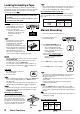
Rear View
AC power socket
This socket connects to the power cord. Insert the cord
firmly.
Input terminals
ALM IN
Use for alarm recording. The alarm sensor is connected
here.
RST IN
Use to stop alarm recording.
• When “ALARM REC DURATION” in “RECORDING
SET UP” menu is set to “MAN1”, the alarm recording
stops when a signal is input to this terminal. The alarm
reset switch is connected here.
• When set to other than “MAN1”, it can be used to
adjust the VCR’s clock.
REC IN
Use to start/stop recording or for series recording.
GND
When a lead connected to other terminals requires a ground,
connect the ground lead here.
Output terminals
ALM OUT
Use to indicate an alarm recording to an external alarm.
MODE OUT
Use to indicate the VCR’s mode of operation.
• When “MODE OUT” in “REAR TERMINAL” menu is
set to “CLOCK ADJ”, the clock of all connected VCR’s
can be adjusted. (
page 21)
CLK OUT
Use to control an external camera switcher.
CALL OUT
Use to indicate when a tape reaches its end during
recording or if there has been a problem during recording.
Battery Box
Battery is stored here.
Note
• This VCR contains a special battery. Consult your dealer
to replace it.
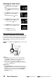
REMOTE jack
Remote control is possible by connecting the remote control
unit (R-9100) here.
page 26
AUDIO IN connector
Audio input connector (RCA pin).
AUDIO OUT connector
Audio output connector (RCA pin).
VIDEO IN connector
Input connector for video signal (BNC connector). Connect
cameras here.
VIDEO OUT connector
Output connector for video signal (BNC connector).
Connect a monitor here. If the VCR is turned off, the signal
from the VIDEO IN connector is looped out to this connector.
RESET button
page 31
Note
Ensure the power cord is not plugged into the outlet before connecting to any rear terminals.
For the rating of each connector at the rear panel of VCR,
page 30.