
Specifications


-
22
-
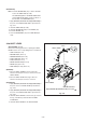
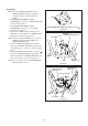
LOADING ARM
ASSY (TU)
Mark
LOADING ARM
ASSY (SP)
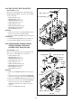
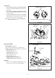
LOADING ARM ASSY (TU)
Apply GREASE (MULTEMP AC-DM) to the parts .
Fig. 2-30-3
Fig. 2-30-2
(Installation)
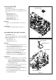
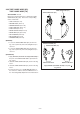
1. Apply GREASE (MULTEMP AC-DM)[859D055O90] to
the parts on the MAIN PLATE ASSY specified in the
Fig. 2-30-1.
2. Apply GREASE (MULTEMP AC-DM)[859D055O90] to
the parts on the LOADING ARM ASSY (TU) specified
in the Fig. 2-30-2.
3. Install the LOADING ARM ASSY (SP) and LOADING
ARM ASSY (TU) so that the Marks on the both UNITs
face each other, as shown in the Fig. 2-30-3.
Note : Be sure to replace the removed LOADING ARM
ASSY (SP) with a new one.
2-31.A/L LEVER
SET POSITION: Upside down
Remove the following parts before replacing the A/L
LEVER. Refer to the corresponding items to install them.
• STAY PLATE (Item 2-2)
• BOTTOM ASSY (Item 2-3)
• MOTOR HOLDER (Item 2-16)
• PINCH ARM CAP (Item 2-17)
• PINCH UNIT (Item 2-17)
• BRAKE CAM PLATE (Item 2-19)
• LOADING ARM ASSY (SP) (Item 2-30)
• LOADING ARM ASSY (TU) (Item 2-30)
(Removal)
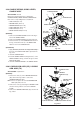
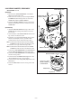
1. Remove the CUT WASHER and WASHER shown in
the Fig. 2-31-1. Then, remove the A/L LEVER.
CUT WASHER
A/L LEVER
WASHER
MAIN PLATE ASSY
GREASE (MOLYKOTE G PASTE)
Fig. 2-31-1