
Specifications

-
3
-
B
A
C
a
Hole in MAIN PLATE ASSY
BOTTOM ASSY
WORM WHEEL
ARM (SP)
Lift
Pull out
Fig. 2-3-1
b
c
d
e
MAIN PLATE ASSY
Groove of MAIN
PLATE ASSY
Side View
GREASE
(MULTEMP AC-DM)
BOTTOM ASSY
ARM (SP)
ARM (TU)
Groove of MAIN
PLATE ASSY
GREASE
(MULTEMP AC-DM)
Side View
Fig. 2-3-2
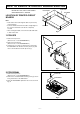
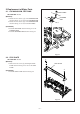
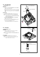
2-3. BOTTOM ASSY
SET POSITION : Normal
Remove the following part before replacing the BOTTOM
ASSY. Refer to the corresponding item to install it.
• STAY PLATE (Item 2-2)
(Removal)
1. Move the WORM WHEEL in the Fig. 2-3-1 in the
direction shown by the arrow A. And match the Boss
a of the BOTTOM ASSY with the Hole in the MAIN
PLATE ASSY.
2. Lift the BOTTOM ASSY in the Fig. 2-3-1 in the
direction shown by the arrow B and pull it out in the
direction shown by the arrow C.
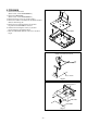
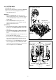
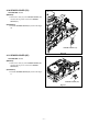
(Installation)
1. Apply GREASE (MULTEMP AC-DM)[859D055O90] to
the Grooves of the MAIN PLATE ASSY shown in the
Fig. 2-3-2.
2. Apply GREASE (MULTEMP AC-DM)[859D055O90] to
the Bosses of the BOTTOM ASSY shown in the Fig.
2-3-2.
3. Rotate the WORM WHEEL shown in the Fig. 2-3-1 so
that the ARM (SP) stands vertically.
4. Insert the Boss b of the BOTTOM ASSY shown in the
Fig. 2-3-2 in the Upper Groove of the MAIN PLATE
and the Boss c in the Lower Groove.
5. Insert the Boss d of the BOTTOM ASSY to the Upper
Groove through the Hole in the MAIN PLATE ASSY
shown in the Fig. 2-3-1 and the Boss e to the Lower
Groove through the slot in the ARM (SP).