2TQ-MiEV(NAS)_Cover2.fm 1 ページ 2011年7月26日 火曜日 午前7時47分 Introduction N09200100934 Thank you for buying a Mitsubishi i-MiEV powered by MiEV (Mitsubishi innovative Electric Vehicle) technology. We are confident you will enjoy your vehicle. It has been engineered for optimum performance, durability and comfort. By thoroughly reading this Owner’s Manual, you will gain an understanding of the many features that are included in the iMiEV.
BK0140800US.
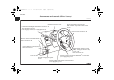
BK0140800US.book 1 ページ 2011年9月29日 木曜日 午後3時28分 Overview Instruments and controls (Driver’s area) N00100201459 Instrument cluster P.3-58 Combination headlights and dimmer switch P.3-76 Turn signal lever P.3-82 Front fog light switch (if so equipped) P.3-83 Wiper and washer switch P.3-84 Rear window wiper and washer switch P.3-87 Electric motor switch P.3-30 Electric remote-controlled outside mirror switch P.3-28 Active Stability Control (ASC) OFF switch P.3-47 Fuses P.
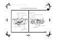
BK0140800US.book 2 ページ 2011年9月29日 木曜日 午後3時28分 Overview Instruments and controls (Instrument panel) N00100201462 Hazard warning flasher switch P.3-83 Audio (if so equipped) P.5-18 Mitsubishi Multi-Communication System (if so equipped) Refer to the separate “Mitsubishi Multi-Communication System owner’s manual” Supplemental restraint system (SRS) airbag (for front passenger’s seat) P.2-35 Side vents P.5-2 Cup holder P.3-130 Glove compartment P.3129 Hood release lever P.7-4 Center vents P.
BK0140800US.book 3 ページ 2011年9月29日 木曜日 午後3時28分 Overview Interior N00100301229 Sun visors P.3-122 Vanity mirror P.3-122 Card holder P.3-122 Dome light (rear) P.3-127 Assist grip P.3-131 Seat belts P.2-13 Supplemental restraint system (SRS) - curtain airbags P.2-52 Dome light (front)/Reading lights P.3-125 Head restraints P.2-10 Inside rearview mirror P.3-26 Window lock switch P.3-24 Tether anchors for child restraint system P.2-28 Tire repair kit P.6-7 Front seat P.
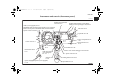
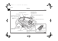
BK0140800US.book 4 ページ 2011年9月29日 木曜日 午後3時28分 Overview Under the hood/Electric motor unit room N00100800025 Under the hood Electric motor unit room Windshield washer fluid reservoir P.7-11 12V starter battery P.7-13 Hot water heater reservoir P.7-7 Brake fluid reservoir P.7-12 Coolant reservoir P.7-7 On board charger/DC-DC converter P.7-2 Brake electric vacuum pump P.3-73 Inverter P.
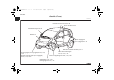
BK0140800US.book 5 ページ 2011年9月29日 木曜日 午後3時28分 Overview Outside (Front) N00100601336 Outside rearview mirrors P.3-28 Power window P.3-22 Windshield wipers P.3-84 Hood P.7-4 Quick charging lid (if so equipped) P.1-33 Main drive lithium-ion battery P.7-2 Front fog lights (if so equipped) P.3-83, 7-36, 7-40 Daytime running lights (if so equipped) P.3-76, 7-36, 7-40 Front side-marker lights P.3-76, 7-36, 7-38 Front turn signal lights P.3-82, 7-36, 7-40 Headlights P.3-76, 7-36 Parking lights P.
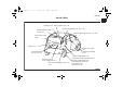
BK0140800US.book 6 ページ 2011年9月29日 木曜日 午後3時28分 Overview Outside (Rear) N00100601307 Antenna P.5-40 Back-up light P.7-36, 7-42 Tail and stop lights P.3-76, 7-36, 7-42 High-mounted stop light P.7-36, 7-45 Rear turn signal lights P.3-82, 7-36, 7-42 Rear window wiper P.3-87 Liftgate P.3-16 Keyless entry system P.3-7 Locking and unlocking P.3-12 License plate lights P.3-76, 7-36, 7-47 Regular charging lid P.1-21 Rear-view camera (if so equipped) P.3-55 Rear side-marker lights P.
BK0140800US.
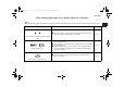
BK0140800US.book 1 ページ 2011年9月29日 木曜日 午後3時28分 Quick index If this warning light comes on or flashes while you’re driving... N00200701110 NOTE ● These warning lights will come on for a few seconds for a bulb check when the electric motor switch is first turned to “ON”. Warning light Do this Ref. page ● Park your vehicle in a safe place and turn off the electric motor unit. Contact a certified i-MiEV dealer for assistance. P.
BK0140800US.book 2 ページ 2011年9月29日 木曜日 午後3時28分 Quick index Warning light Anti-lock braking system warning light Do this Ref. page ● When this light comes on, the anti-lock braking system is not functioning and only the ordinary braking system is functioning. ● Park your vehicle in a safe place and stop the electric motor unit. Test the system as described on page 3-43.
BK0140800US.book 3 ページ 2011年9月29日 木曜日 午後3時28分 Quick index Warning light Do this Ref. page ● Have the transmission checked at a certified i-MiEV dealer as soon as possible. P.3-34 ● Park your vehicle in a safe place and turn off the electric motor unit. Restart the electric motor unit and check to see if the indicator comes on again. ● If the indicator does not go out, or if it comes on again, have your vehicle inspected at a certified i-MiEV dealer as soon as possible.
BK0140800US.book 4 ページ 2011年9月29日 木曜日 午後3時28分 Quick index If this problem occurs... N00200900841 Problem Cannot turn the key. Do this Ref. Page From “LOCK” to “ACC”. Turn the key while turning the steering wheel in either direction. From “ACC” to “LOCK”. Check the position of the selector lever. The key cannot be removed unless the selector lever is set to the “P” (PARK) position. Cannot shift the selector lever from Shift the selector lever while pressing the brake pedal. the “P” (PARK) position.
BK0140800US.book 5 ページ 2011年9月29日 木曜日 午後3時28分 Quick index Problem Do this Ref. Page The electric motor unit does not start. The lights do not come on. The lights are dim. The horn does not honk. The horn sound is weak. Cannot charge the main drive lithium-ion battery. Have the 12V starter battery checked. Recharge or replace as needed. P.6-2, 7-13 The vehicle is stuck in sand, mud, or snow. Rock your vehicle back and forth to free it. P.
BK0140800US.book 6 ページ 2011年9月29日 木曜日 午後3時28分 Quick index Problem The brakes are not functioning properly after driving through water. Do this Dry out the brakes by driving slowly while lightly pressing the brake pedal. Ref. page P.4-8 A tire is punctured. 1. Park the vehicle in a safe place where the surface is flat and level. 2. Repair the flat tire with tire repair kit. 6 P.
BK0140800US.book 1 ページ 2011年9月29日 木曜日 午後3時28分 General information/Charging Familiarizing yourself with i-MiEV . . . . . . . . . . .1Modifications to and racing of your vehicle . . . . .1Mitsubishi Motors genuine parts . . . . . . . . . . . . . .1California Perchlorate Materials Requirements. . .1Cautions and actions to deal with intense heat . . .1Cautions and actions to deal with intense cold . . .1Charging. . . . . . . . . . . . . . . . . . . . . . . . . . . . . . . . .
BK0140800US.book 2 ページ 2011年9月29日 木曜日 午後3時28分 General information/Charging Familiarizing yourself with i-MiEV N01200100013 1 i-MiEV is a pure electric vehicle. Some of the vehicle systems operate differently from and have different characteristics than ordinary vehicles equipped with an internal combustion engine. For this reason, it is very important to read carefully this entire owner’s manual. Main features N01200200014 ● i-MiEV is powered only by electricity.
BK0140800US.book 3 ページ 2011年9月29日 木曜日 午後3時28分 General information/Charging ! WARNING ● Keep the brake pedal depressed until you are ready to drive. When the vehicle is in the “D” (DRIVE), “ECO” (ECO MODE), “B” (REGENERATIVE BRAKE MODE) or “R” (REVERSE) position, if you release the brake pedal and even if you do not depress accelerator, the vehicle will creep and may move slowly. Regenerative braking N01205600013 It is equivalent to engine braking of a gasoline or diesel powered vehicle.
BK0140800US.book 4 ページ 2011年9月29日 木曜日 午後3時28分 General information/Charging Main drive lithium-ion battery N01200300015 ! 1 WARNING ● The main drive lithium-ion battery is a sealed high voltage battery and has no user serviceable parts. • To avoid severe burns and/or electrical shock that may result in serious injury or death, never attempt to detach the main drive lithium-ion battery from the vehicle or try to disassemble it.
BK0140800US.book 5 ページ 2011年9月29日 木曜日 午後3時28分 General information/Charging ● Mitsubishi Motors estimates that after 5 years, the capacity of the main drive lithium-ion battery provided with your vehicle will be approximately 80% of the original capacity. After 10 years, the capacity should be approximately 70% of the original capacity.
BK0140800US.
BK0140800US.book 7 ページ 2011年9月29日 木曜日 午後3時28分 General information/Charging Modifications to and racing of your vehicle Installation of accessories N01200600018 N01200500017 This vehicle should not be modified with non-Mitsubishi Motors genuine parts. Mitsubishi Motors designs and manufactures high quality vehicles with an emphasis on safety and durability.
BK0140800US.book 8 ページ 2011年9月29日 木曜日 午後3時28分 General information/Charging Important point! 1 Due to the large number of accessory and replacement parts provided by different manufacturers in the market, it is not always possible for a certified i-MiEV dealer to check whether the attachment or installation of non-Mitsubishi Motors genuine parts will affect the driving safety of your Mitsubishi-vehicle.
BK0140800US.book 9 ページ 2011年9月29日 木曜日 午後3時28分 General information/Charging Mitsubishi Motors genuine parts N01200800010 Mitsubishi Motors Genuine Parts are designed and manufactured to meet high standards of performance, and are recommended for all of your maintenance needs. Also available from a certified i-MiEV dealer are a wide variety of accessories to personalize your new vehicle.
BK0140800US.book 10 ページ 2011年9月29日 木曜日 午後3時28分 General information/Charging Cautions and actions to deal with intense heat N01201000019 1 ● When the vehicle is driven in a high ambient temperature, its air-conditioner performance can be insufficient. Also, using the air conditioner will reduce the vehicle’s cruising range. ● When the ambient temperature is approximately 104 °F (40 °C) or higher, the phenomena described below may occur. Please take the described actions.
BK0140800US.book 11 ページ 2011年9月29日 木曜日 午後3時28分 General information/Charging Approx. ambient temperature Phenomena Approx.113 °F Startup and driving (45 °C) or higher • During quick charging (if so equipped), repeated highspeed driving, or repeated uphill driving, the power down warning light* comes on and the motor output is restricted to protect the main drive lithium-ion battery and/or motor (electric motor unit). • Regenerative braking performance may decrease.
BK0140800US.book 12 ページ 2011年9月29日 木曜日 午後3時28分 General information/Charging Cautions and actions to deal with intense cold N01201100010 ● When the vehicle is driven in a low ambient temperatures, its heater performance can be insufficient. Also, using the heater can reduce the vehicle’s cruising range. ● When the ambient temperature is approximately 5 °F (-15 °C) or lower, the phenomena described below may occur. Please take the corrective actions described below. 1 Approx. ambient temperature Approx.
BK0140800US.book 13 ページ 2011年9月29日 木曜日 午後3時28分 General information/Charging Approx. ambient temperature Approx.-13 °F (-25 °C) or lower Phenomena Startup and driving Charging and battery Approx. -22 °F (-30 °C) or lower Startup and driving Charging and battery Corrective action • Motor output is restricted, and the power down warning • Keep driving if you can drive at the 1 same speed as surrounding vehicles. light* may come on.
BK0140800US.book 14 ページ 2011年9月29日 木曜日 午後3時28分 General information/Charging NOTE ● *1: Refer to “Power down warning light” on page 3-75. Illumination of the power down warning light does not indicate a malfunction. ● *2: Refer to “Ready indicator” on page 3-72.
BK0140800US.book 15 ページ 2011年9月29日 木曜日 午後3時28分 General information/Charging Charging N01201200011 Your vehicle is equipped with a charge port and a charging cable (EV charging cable) for charging with a AC 110-120V or a AC 220-240V outlet. Additionally your vehicle may be equipped with another charge port for quick charging capable for CHAdeMO quick charger. Category Charge port Charge connector Charging Source Charging time with fully discharged battery Reference About 22 hours P.
BK0140800US.book 16 ページ 2011年9月29日 木曜日 午後3時28分 General information/Charging Category 1 Charge port Charge connector Charging Source Level 2 Regular charging 220-240V (Primary Home EVSE* DockAvailable separately) passenger side of vehicle *: EVSE = Electric Vehicle Supply Equipment 1-16 Reference About 6 hours P.1-20, 132 About 30 minutes for 80 % charge P.
BK0140800US.book 17 ページ 2011年9月29日 木曜日 午後3時28分 General information/Charging Charging time will vary depending on battery condition, air temperature and condition of power source (such as specification of the quick charger). A vehicle equipped with a quick charge port is compatible with most CHAdeMO (Japanese industry standard) connectors on charging stations. Charging stations using the CHAdeMO standard are UL certified and safe to use in the US.
BK0140800US.book 18 ページ 2011年9月29日 木曜日 午後3時28分 General information/Charging Precautions during Charging the Main Drive Lithium-ion Battery N01202600012 ! 1 WARNING ● Improper charging can result in a fire, property damage, and serious injury or death. Read the instructions described below carefully and follow them.
BK0140800US.book 19 ページ 2011年9月29日 木曜日 午後3時28分 General information/Charging ! CAUTION ● To prevent damage to the charging equipment: • Do not close the charge port lid without closing the cap. • Do not subject the charging equipment to impact. • Do not pull or twist the charge cable. • Do not drag the charge cable. • Do not store charging equipment in locations where the temperature is above 185 °F (85 °C) or below -40 °F (-40 °C).
BK0140800US.book 20 ページ 2011年9月29日 木曜日 午後3時28分 General information/Charging Regular charging (charging method with rated AC 120 V outlet) N01203100014 1 Carefully read instructions regarding “Precautions during charging the main drive lithium-ion battery” on page 1-18 and described in this section and also instructions on “EV charging cable” on page 1-28 or instructions for a charging device you use, and follow them.
BK0140800US.book 21 ページ 2011年9月29日 木曜日 午後3時28分 General information/Charging Charging from rated AC 120 V outlet 5. Press the tab (C) to open the inner lid (D). N01203200015 1. Fully apply the parking brake and place the selector lever to the “P” (PARK) position. 2. Stop the electric devices such as lamps and turn the electric motor switch to the “LOCK” position. 3.
BK0140800US.book 22 ページ 2011年9月29日 木曜日 午後3時28分 General information/Charging ! CAUTION ● To help keeping foreign material out of the charge port, do not leave the inner lid open without connecting the charge connector. 1 NOTE ● There is a hole on the charge port for water drainage. If this hole is blocked and water gets trapped in the charge port, do not charge. Contact a certified i-MiEV dealer. ● If the charge port becomes frozen, use a hair dryer to defrost and dry the port before charging.
BK0140800US.book 23 ページ 2011年9月29日 木曜日 午後3時28分 General information/Charging 7. Open the cap (F) on the regular charge connector (G) and make sure that there is no foreign matter such as dust at the end of the regular charge connector and the regular charge port. 8. Connect the regular charge connector until a click is heard without pressing the button (H).
BK0140800US.book 24 ページ 2011年9月29日 木曜日 午後3時28分 General information/Charging ! CAUTION ● Do not clasp the top of regular charge connector. It could cause injury to from the protrusion on the lid. 9. Make sure that the charging indicator on the instrument cluster is illuminated. 1 NOTE ● If the electric motor switch is turned to the “START” position with the regular charge connector connected to the regular charge port, the electric motor unit cannot be started.
BK0140800US.book 25 ページ 2011年9月29日 木曜日 午後3時28分 General information/Charging NOTE ● When the regular charge connector is connected to the charge port, the charging indicator is blinking. When charging is started, the charging indicator is illuminated. ● The charge level for main drive lithium-ion battery can be checked with the energy level gauge (I) on the instrument cluster. Refer to “Energy level gauge” on page 3-69. 10. Charging is complete when the charging indicator turns off.
BK0140800US.book 26 ページ 2011年9月29日 木曜日 午後3時28分 General information/Charging 11. Close the inner lid and close the regular charging lid. NOTE 1 ● Make sure that the inner lid is completely closed before closing the regular charging lid. If the regular charging lid is forcibly closed without completely closing the inner lid, the hinge on the inner lid may be broken. 12. Remove the charging cable plug from the outlet. 13. Install the cap on the regular charge connector.
BK0140800US.book 27 ページ 2011年9月29日 木曜日 午後3時28分 General information/Charging The energy level gauge (A) in the instrument cluster and charging indicator (B) illuminate while the main drive lithium-ion battery warming system is operating. The main drive lithium-ion battery warming system will automatically stop when the main drive lithium-ion battery temperature is -4°F (-20°C) or higher.
BK0140800US.book 28 ページ 2011年9月29日 木曜日 午後3時28分 General information/Charging EV charging cable N01202800014 Your vehicle is equipped with an EV charging cable that consists of a cable (A), control box (B), plug (C) and regular charge connector (D).
BK0140800US.book 29 ページ 2011年9月29日 木曜日 午後3時28分 General information/Charging READY (Green) CHARGE (Orange) FAULT (Red) Status and action to be taken While the main drive lithium-ion battery is being charged When the ground cable is disconnected Check the grounding of the outlet being used. If the outlet is properly grounded, contact a certified i-MiEV dealer. When an electric leakage occurs or the EV charging cable malfunctions Stop use immediately and contact a certified i-MiEV dealer.
BK0140800US.book 30 ページ 2011年9月29日 木曜日 午後3時28分 General information/Charging ! 1 WARNING ● Improper use of the EV charging cable can result in a fire, property damage, and serious injury or death. Carefully read instructions regarding “Precautions during charging the main drive lithium-ion battery” on page 1-18 and on “Regular charging (charging from rated AC 120 V outlet)” on page 1-21 and described in this section and follow them.
BK0140800US.book 31 ページ 2011年9月29日 木曜日 午後3時28分 General information/Charging Handling and storing the control box N01202900015 ! CAUTION ● Use the method shown below to help secure the control box and to prevent the plug from being pulled halfway out of the socket during charging. NOTE ● Use hook and a rope that can support the weight of the EV charging cable, 8.8 lbs (4 kg) as shown in the figure below. ● Make sure that the rope has no damage before use.
BK0140800US.book 32 ページ 2011年9月29日 木曜日 午後3時28分 General information/Charging Cleaning the EV charging cable N01203000013 1 1. Gently wipe outside surface of the EV charging cable with gauze or a similar soft cloth soaked with a mild soap and water solution. 2. Wipe off all detergent with a soft cloth dipped in fresh water and thoroughly wrung out. 3. Wipe all moisture off and dry in a shaded, well-ventilated area.
BK0140800US.book 33 ページ 2011年9月29日 木曜日 午後3時28分 General information/Charging Quick charging (charging method with quick charger) (if so equipped) N01203300016 Your vehicle may be equipped with the quick charging port. The quick charge port is compatible with most CHAdeMO* (Japanese industry standard) connectors on charging stations. *: Charging stations using this standard are UL certified and safe to use in the US. Improper charging can result in a fire, property damage, and serious injury or death.
BK0140800US.book 34 ページ 2011年9月29日 木曜日 午後3時28分 General information/Charging 3. Pull the quick charging lid opener (A) at the bottom left of the driver’s seat to open the quick charging lid (B) at the left rear side of the vehicle. 5. Press the tab (C) to open the inner lid (D). D A E C 1 B 4. Remove key and lock the vehicle. 1-34 ! WARNING ● Do not touch the metal terminal of the quick charge port (E) and the quick charge connector. Doing so could cause an electric shock and/or malfunction.
BK0140800US.book 35 ページ 2011年9月29日 木曜日 午後3時28分 General information/Charging ! CAUTION ● Be sure to insert the quick charge connector straight into the quick charge port all the way to the base. Failure to do so may result in the main drive lithium-ion battery not charging or cause damage to the charging equipment. ● Do not leave the inner lid open for any significant period of time without the charge connector inserted.
BK0140800US.book 36 ページ 2011年9月29日 木曜日 午後3時28分 General information/Charging 7. Make sure that the charging indicator on the instrument cluster is illuminated. 1 NOTE ● When the quick charging plug is connected to the charging connection, the charging indicator will blink. Once charging has started, the charging indicator will illuminate. ● The charge level for the main drive lithium-ion battery can be checked with the energy level gauge (F) on the instrument cluster.
BK0140800US.book 37 ページ 2011年9月29日 木曜日 午後3時28分 General information/Charging ● Since the main drive lithium-ion battery cooling system uses cool air from the air conditioning system, the air conditioning will automatically be operated. After quick charging, you may find dehumidified water from the air conditioning system under the vehicle. It is not a malfunction. 8. Charging is complete when the charging indicator turns off.
BK0140800US.book 38 ページ 2011年9月29日 木曜日 午後3時28分 General information/Charging Charging troubleshooting guide N01202300019 Symptom Charging cannot be started. 1 Regular charging cannot be started. Possible cause Possible solution The electric motor switch is in the ON position. Before charging, place the electric motor switch in the “LOCK” position. The main drive lithium-ion battery is already fully charged.
BK0140800US.book 39 ページ 2011年9月29日 木曜日 午後3時28分 General information/Charging Symptom Regular charging is discontinued. Possible cause Possible solution There is no power coming from the outlet. There may have been a electrical power failure, or the breaker may have failed.Charging will resume when the power source is reset. The EV charging cable has been disconnected. Check that the EV charging cable has not been disconnected.
BK0140800US.book 40 ページ 2011年9月29日 木曜日 午後3時28分 General information/Charging Symptom Quick charge is discontinued. Possible cause Charging is stopped by the quick Charging will stop depending on the timer function setting of the quick charge timer. charge device.If you need to charge the main drive lithium-ion battery more, start the charging procedure again. Charging stops at 80% capacity. Charging is designed to stop when the main drive lithium-ion battery capacity reaches 80%.
BK0140800US.book 41 ページ 2011年9月29日 木曜日 午後3時28分 General information/Charging High-Voltage components N01205700014 ! High voltage components and wiring cables are located as shown in the figure below. WARNING ● The EV (Electric Vehicle) system uses high voltage up to DC 330 volt. The system can be hot during and after starting and when the vehicle is shut off. Be careful of both the high voltage and the high temperature. Follow the warning labels that are attached to the vehicle.
BK0140800US.book 42 ページ 2011年9月29日 木曜日 午後3時28分 General information/Charging In case of a collision N01205800015 In case of a collision, follow the instructions described below to avoid severe burns and electrical shock that may result in serious injury or death. 1 ! WARNING ● If your vehicle is drivable, pull your vehicle off the road in a safe place, move the selector lever to the P (PARK) position, apply the parking brake and turn the electric motor switch to the lock position.
BK0140800US.book 43 ページ 2011年9月29日 木曜日 午後3時28分 General information/Charging NOTE ● The emergency shut-off system will be activated and the high-voltage system will automatically turn off under the following conditions: • Front and side collisions in which the air bags are deployed. • Certain rear collisions. • Certain EV (Electric Vehicle) system malfunctions ● When the emergency shut-off system is activated, the ready indicator is turned off. Refer to “Indicator and warning light package” on page 3-71.
BK0140800US.book 44 ページ 2011年9月29日 木曜日 午後3時28分 General information/Charging ! 1 WARNING ● Individuals who use implantable pacemakers or implantable cardiovascular-defibrillators should keep away from the external and internal transmitters. The electromagnetic waves used in the MiEV Remote System may affect the operation of implantable pacemakers and implantable cardiovasculardefibrillators.
BK0140800US.book 45 ページ 2011年9月29日 木曜日 午後3時28分 General information/Charging ● Melody and buzzer from the MiEV Remote can be turned on or off. Refer to “To turn on/off melody and buzzer” on page 163. ● The transmitter signal will reach further when the antenna of the MiEV Remote is fully extended and held upright. ● The onboard antenna is printed on the right side delta glass of the vehicle. ● When the MiEV Remote is not used for more than 30 seconds, the MiEV Remote will automatically turn off.
BK0140800US.book 46 ページ 2011年9月29日 木曜日 午後3時28分 General information/Charging MiEV Remote N01203500018 1 • When the MiEV Remote is on, the MiEV Remote can be turned off by pressing the switch for 3 seconds or more. 2. MODE switch The display of the MiEV Remote is changed in order of “ON timer”, “OFF timer” and “Remote Climate Control” by pressing this switch. 3. The manual charge switch ON timer, OFF timer and Remote Climate Control are cancelled by pressing this switch. 4. Ring 5.
BK0140800US.book 47 ページ 2011年9月29日 木曜日 午後3時28分 General information/Charging 3_ When communicating with the vehicle, the MiEV Remote display blinks if a communication error occurs or the MiEV Remote is not functioning properly. If the buzzer sounds while this indicator blinks, a problem has been detected. Refer to “Actions to be taken when the MiEV Remote system does not operate correctly” on page 1-67. NOTE ● The buzzer can be turned off. Refer to “To turn on/off melody and buzzer” on page 1-63.
BK0140800US.book 48 ページ 2011年9月29日 木曜日 午後3時28分 General information/Charging ! 1 CAUTION ● Never leave the MiEV Remote in place where it will be subject to high temperatures, such as in direct sunlight, or subject to extreme low temperatures. The MiEV Remote can be damaged and may not properly operate. ● Never drop or hit the MiEV Remote. Do not apply force to bend the antenna. These can cause damage to or failure of the remote. ● If the MiEV Remote gets wet, please wipe water off immediately.
BK0140800US.book 49 ページ 2011年9月29日 木曜日 午後3時28分 General information/Charging Example of Charging Timer N01205000017 1. Setting of ON Timer = 2h, OFF Timer = 8h 2. When Charging timers are set up, initially 4h for ON-Timer and 8h for OFF-Timer are displayed.
BK0140800US.book 50 ページ 2011年9月29日 木曜日 午後3時28分 General information/Charging To turn the MiEV Remote ON/OFF 1 To set the ON timer N01205100018 N01205200019 1. Extend the antenna (A) and press the power/communication switch (B) for 1 second or more to turn the MiEV Remote on. When it communicates with the vehicle properly, the vehicle information will be displayed on the screen. 1. Start the regular charging. Refer to “Regular charging (charging method with rated AC 120 V outlet)” on page 120. 2.
BK0140800US.book 51 ページ 2011年9月29日 木曜日 午後3時28分 General information/Charging NOTE ● The remaining time for the last charging is displayed with blinking as follows. Example: If you set the charging starting time to 11:00 PM of the day before: Present time Remaining time Display 9:00 PM 2:00 2h 9:10 PM 1:50 2h 9:40 PM 1:20 1.5h 4. If you need to change the remaining time for the ON timer, press the UP switch (C) or the DOWN switch (D) to change the remaining time.
BK0140800US.book 52 ページ 2011年9月29日 木曜日 午後3時28分 General information/Charging 5. Press the power/communication switch (B) for less than 1 second to send the setting data to the vehicle. The MiEV Remote will sound melodies on transmission and reception. NOTE 1 ● The melodies can be turned off. Refer to “To turn on/off melody and buzzer” on page 1-63. ● If a communication error occurs or the MiEV Remote System is not functioning properly, the buzzer will sound.
BK0140800US.book 53 ページ 2011年9月29日 木曜日 午後3時28分 General information/Charging ● Turning the electric motor switch to the “ON” position or the “ACC” position will cancel the Charging Timer. ● If the MODE switch is pressed while changing the ON timer setting, the change will be canceled. ● The symbol on the MiEV Remote will be illuminated while the vehicle is charging. ● If the charge connector is disconnected before the time set by the ON timer, the Charging Timer is not canceled.
BK0140800US.book 54 ページ 2011年9月29日 木曜日 午後3時28分 General information/Charging 5. Turn off the MiEV Remote. Refer to “To turn the MiEV Remote ON/OFF” on page 1-50. 1 To set OFF Timer N01205300010 The OFF timer can be set during the regular charging or after setting the ON timer. 1. When the power of MiEV Remote is off, turn the power on. Refer to “To turn the MiEV Remote ON/OFF” on page 1-50. 2. Press the MODE switch (E) to change the display to the OFF timer (2).
BK0140800US.book 55 ページ 2011年9月29日 木曜日 午後3時28分 General information/Charging 3. Press the UP switch (C) or the DOWN switch (D) once. The time set last time for the OFF timer will be displayed and blink. 5. Press the power/communication switch (B) for less than 1 second to send the setting data to the vehicle. The MiEV Remote will sound melodies on transmission and reception. NOTE ● The melodies can be turned off. Refer to “To turn on/off melody and buzzer” on page 1-63.
BK0140800US.book 56 ページ 2011年9月29日 木曜日 午後3時28分 General information/Charging NOTE 1 ● The energy level gauge in the instrument panel will illuminate and the charging indicator will blink approximately 30 seconds after the vehicle has received the setting for the OFF timer. After approximately 30 seconds, the energy level gauge and the charging indicator will then go off, and the vehicle will be prepared for Charging Timer in accordance with the ON/OFF setting.
BK0140800US.book 57 ページ 2011年9月29日 木曜日 午後3時28分 General information/Charging Display of MiEV Remote during communicating with vehicle N01203800011 It communicates with the vehicle when the power of the MiEV Remote is turned on with pressing the power supply/communication switch (B) for 1 second or more and if the power supply/communication switch (B) is pressed for less than 1 second while the power of the MiEV Remote is on.
BK0140800US.book 58 ページ 2011年9月29日 木曜日 午後3時28分 General information/Charging 2. Press the manual charging switch (H), then press the power/communication switch (B) for less than 1 second. 1 NOTE ● If the manual charging switch (H) is pressed, the symbol of MiEV Remote will blink. Remote Climate Control is also stopped. 3. Canceling Charging Timer is complete, and the MiEV Remote will sound two different melodies. 4. Turn off the MiEV Remote. Refer to “To turn the MiEV Remote ON/OFF” on page 1-50.
BK0140800US.book 59 ページ 2011年9月29日 木曜日 午後3時28分 General information/Charging Remote Climate Control NOTE N01204200012 ! WARNING ● The Remote Climate Control, even when set, cannot be relied upon to maintain safe vehicle cabin temperatures while the vehicle is stopped or parked. Never leave children or persons requiring supervision/nursing unattended inside the vehicle.
BK0140800US.book 60 ページ 2011年9月29日 木曜日 午後3時28分 General information/Charging To operate the Remote Climate Control N01204300013 1 The following conditions must be met to operate the Remote Climate Control. ● Selector lever: P (PARK) position. ● Electric motor switch: LOCK position. ● EV charging cable (regular charger): Connected. ● Quick charging: Not used (if so equipped). ● Main Drive Lithium-ion Battery Level Indicator: Shows one bar or more.
BK0140800US.book 61 ページ 2011年9月29日 木曜日 午後3時28分 General information/Charging 4. Select a desired mode by pressing UP switch (C) or DOWN switch (D). The modes will be changed in the order from 1 to 4 by pushing the UP switch.
BK0140800US.book 62 ページ 2011年9月29日 木曜日 午後3時28分 General information/Charging 5. Press the power/communication switch (B) for less than 1 second to send the setting to the vehicle. The MiEV Remote will sound melodies on transmission and reception. A. By using the MiEV Remote, after pressing the manual charging switch (H), press the power/communication switch (B) for less than 1 second. NOTE 1 ● The melodies can be turned off. Refer to “To turn on/off melody and buzzer“ on page 1-63.
BK0140800US.book 63 ページ 2011年9月29日 木曜日 午後3時28分 General information/Charging Main Drive Lithium-ion Battery Level Indicator To turn on/off melody and buzzer N01204100011 N01204500015 1. Turn on the MiEV Remote. Refer to “To turn the MiEV Remote ON/OFF” on page 1-50. • To turn off the sounds, press the UP switch (C) while pressing MODE switch (E). • To turn on the sounds, press the DOWN switch (D) while pressing MODE switch (E).
BK0140800US.book 64 ページ 2011年9月29日 木曜日 午後3時28分 General information/Charging The remening energy is shown by the number of segments displayed. : 3 segments: Full or near full : 2 segments: Moderate : 1 segment: Low 1 : 0 segments: Empty or near empty NOTE ● More than remained quantity in the Main Drive Lithium-ion Battery is necessary to operate the Remote Climate Control. 3. Turn off the MiEV Remote. Refer to “To turn the MiEV Remote ON/OFF” on page 1-50.
BK0140800US.book 65 ページ 2011年9月29日 木曜日 午後3時28分 General information/Charging Replacement of batteries for the MiEV Remote N01204600016 ! 2. Battery cover (B) lifts when the slide portion (A) is moved to the arrow direction. CAUTION ● MiEV Remote is a precision electronic device with a built-in signal transmitter. Do not disassemble or touch an internal parts. Keep away from water or dust. ● Be careful not to break the tab on the battery cover when removing or installing the battery cover.
BK0140800US.book 66 ページ 2011年9月29日 木曜日 午後3時28分 General information/Charging 3. By moving the battery cover (B) in the arrow direction, tabs (C) on the battery cover will come out and the battery cover can be removed. 5. Install two new coin type CR2032 batteries (D) with the “+” side up. 1 Coin type batteries CR2032 4. Remove the old batteries. 6. Attach the battery cover (A) in the reverse order from the way you have detached it. 7. Confirm the MiEV Remote can be turned ON.
BK0140800US.book 67 ページ 2011年9月29日 木曜日 午後3時28分 General information/Charging Actions to be taken when the MiEV Remote system does not operate correctly N01204900019 Take the following actions when the system does not operate correctly. If the system still does not operate correctly after the action(s) have been taken, a system component may not be working properly. Please consult with a certified i-MiEV dealer to check it.
BK0140800US.book 68 ページ 2011年9月29日 木曜日 午後3時28分 General information/Charging Phenomena 1 The following symbol blinks when the power supply/communication switch on the MiEV Remote is pressed. ● ERROR symbol ● symbol Blinks after about 1 second. Blinks after about 10 seconds. Cause Remedy ● Electrical noise source is present in Move away from the noise source. the vicinity of the MiEV Remote. (e.g. personal computer) ● Electrical noise source is present between the vehicle and the MiEV Remote.
BK0140800US.book 69 ページ 2011年9月29日 木曜日 午後3時28分 General information/Charging Phenomena Charging Timer is After the power/comnot possible. munication switch is pressed, the following symbol blinks in several seconds. ● ERROR symbol ● symbol Cause Remedy Regular charge connector is not inserted Lock the regular charge connector securely. or not locked completely.
BK0140800US.book 70 ページ 2011年9月29日 木曜日 午後3時28分 General information/Charging Phenomena Timed charging is The system is charged impossible. although the ON timer is being set. Charging is preset, but the specified charging level is not satisfied. ● The charging level is not expected amount. ● Is not charged. ● Is not charged at the preset time. 1 Although the charging is preset, too much time is needed to charge the system fully.
BK0140800US.book 71 ページ 2011年9月29日 木曜日 午後3時28分 General information/Charging Phenomena Cause Remedy Timed charging is It is not fully charged. impossible. If the charging unit is equipped with the Preset the Charging Timer while the charging timer function, the power supply to the unit with timer function is powered on. unit has been cut off. The Remote Cli- After the power/commate Control can- munication switch is not be activated. pressed, the following symbol blinks in several seconds.
BK0140800US.book 72 ページ 2011年9月29日 木曜日 午後3時28分 General information/Charging Phenomena 1 The Remote Cli- After the power/commate Control can- munication switch is not be activated. pressed, the following symbol blinks in several seconds. ● ERROR symbol Cause Any of the door or liftgate is open. Remedy Close all the doors and liftgate. The selector lever is at the position other Place the selector lever to P (PARK) position. than P (PARK). Quick charging is in progress.
BK0140800US.book 73 ページ 2011年9月29日 木曜日 午後3時28分 General information/Charging Phenomena The Remote Cli- The heated seat is not mate Control can- powered on. not be activated. The heated seat becomes hot while the air conditioning (cooling) is activated. Cause Remedy The heated seat switch is turned off. Turn on the heated seat switch. The heated seat switch is turned on. Turn off the heated seat switch. 1 Cleaning the MiEV Remote N01203600019 1.
BK0140800US.
BK0140800US.book 1 ページ 2011年9月29日 木曜日 午後3時28分 Seat and restraint systems Seats . . . . . . . . . . . . . . . . . . . . . . . . . . . . . . . . . . . .2Seats and restraint systems. . . . . . . . . . . . . . . . . . .2Front seats . . . . . . . . . . . . . . . . . . . . . . . . . . . . . . .2Rear seats . . . . . . . . . . . . . . . . . . . . . . . . . . . . . . . .2Head restraints . . . . . . . . . . . . . . . . . . . . . . . . . . . .2Seat belts . . . . . . . . . . . . . . . . . . . . . . . . . . . . . . . .
BK0140800US.book 2 ページ 2011年9月29日 木曜日 午後3時28分 Seat and restraint systems Seats N00408400466 2 1 - Front seats ● ● ● ● 2-2 To adjust the seat forward or backward → P.2-5 To adjust the seatback → P.2-5 To adjust the seat height (Driver’s side only) → P.2-6 Heated seat (Driver’s side only) → P.2-7 2 - Rear seats ● To adjust the seatback → P.2-8 ● Folding the seatbacks forward → P.
BK0140800US.book 3 ページ 2011年9月29日 木曜日 午後3時28分 Seat and restraint systems Front seats Seats and restraint systems N00401600209 N00401800386 Your vehicle has seat belts and other features that help protect you and your passengers in an accident. Seat belts are the most important safety device. When worn properly, seat belts can reduce the chance of serious injury or death in various types of crashes.
BK0140800US.book 4 ページ 2011年9月29日 木曜日 午後3時28分 Seat and restraint systems ! 2 WARNING ● Do not attempt to adjust the seat while driving. This can cause loss of vehicle control and result in an accident. ● After adjusting the seat, make sure that the seat is securely locked into position.
BK0140800US.book 5 ページ 2011年9月29日 木曜日 午後3時28分 Seat and restraint systems To adjust the seat forward or backward To adjust the seatback N00401900303 N00402000356 Pull the seat adjusting lever up and slide the seat forward or backward to the desired position. Release the adjusting lever to lock the seat in place. To adjust the seatback, lean forward slightly, gently pull the seatback lock lever up, then lean backward to a comfortable position and release the lever. The seatback will lock in place.
BK0140800US.book 6 ページ 2011年9月29日 木曜日 午後3時28分 Seat and restraint systems ! 2 WARNING ● To reduce the risk of serious injury or death in the event of an accident or sudden stop, all seatbacks should be kept in the upright position while the vehicle is in motion. Seat belt performance during an accident can be adversely affected if the seatbacks are reclined. The more a seatback is reclined, the more likely seat belt performance will be adversely affected.
BK0140800US.book 7 ページ 2011年9月29日 木曜日 午後3時28分 Seat and restraint systems Heated seat (Driver’s side only) N00435600323 The heated seat can be operated when the electric motor switch is in the “ON” position. ! CAUTION ● Switch off the seat heater when not in use. ● Do not place heavy objects on the seat or stick pins, needles, or other pointed objects into the seat.
BK0140800US.book 8 ページ 2011年9月29日 木曜日 午後3時28分 Seat and restraint systems Rear seats To adjust the seatback N00402500218 ! CAUTION ● Child restraint lower anchorages (A) are provided between the seat cushion and the seatback. Be careful that the lower anchorages may be hot due to heat of the electric motor unit room. N00402800022 To adjust the seatback, lean forward slightly, gently pull the seatback lock lever, then lean backward to a comfortable position and release the lever.
BK0140800US.book 9 ページ 2011年9月29日 木曜日 午後3時28分 Seat and restraint systems Folding the seatbacks forward N00402900182 The rear seatbacks can be folded forward to provide additional luggage compartment space. Pull the lever, and fold the rear seatbacks forward. Confirm that the seatback locks securely when it is returned. ! WARNING ● Do not allow anyone to ride in the center of rear seat or in the luggage compartment vehicle is in motion.
BK0140800US.book 10 ページ 2011年9月29日 木曜日 午後3時28分 Seat and restraint systems Head restraints N00404300571 Padded head restraints for the seats can reduce the risk of a whiplash injury if your vehicle is hit from the rear. The head restraints are equipped in the illustrated position. To maximize the effectiveness of your head restraint, seatback to the upright position, and the head restraint to the proper position. Sit back against the seatback with your head close to the head restraint.
BK0140800US.book 11 ページ 2011年9月29日 木曜日 午後3時28分 Seat and restraint systems Adjustment of the head restraint height To remove To reduce the risk of injury in an accident, adjust the head restraint height so that the center of the restraint is at your eye level when seated. Any person too tall for the restraint to reach their eye level when seated should raise the restraint to the highest locked position. ● To raise the restraint, pull it straight up.
BK0140800US.book 12 ページ 2011年9月29日 木曜日 午後3時28分 Seat and restraint systems ! CAUTION ● Check that the lock knob (A) is extended out as shown in the illustration. Then pull the head restraint up to make sure that it is locked in place and will not come out of the seatback. 2 2-12 ! CAUTION ● The shape and size of the head restraint differs according to the seat. Always use the correct head restraint provided for the seat and do not install the head restraint in the wrong direction.
BK0140800US.book 13 ページ 2011年9月29日 木曜日 午後3時28分 Seat and restraint systems Seat belts N00406000471 Seat belts are installed in your vehicle to help reduce the risk of injury to the driver and passenger in the event of an accident. Always use the provided seat belts. Carefully review the following information for proper seat belt usage. ! WARNING ● To help reduce the risk of injury or death in an accident, seat belts and child restraint systems must always be used.
BK0140800US.book 14 ページ 2011年9月29日 木曜日 午後3時28分 Seat and restraint systems Seat belt instructions N00406200457 All seats are equipped with a seat belt which uses one combined lap-and-shoulder belt with an emergency locking retractor. 2 This system is designed to provide both comfort and safety. It permits full extension and automatic retraction of the belts during normal vehicle operation.
BK0140800US.book 15 ページ 2011年9月29日 木曜日 午後3時28分 Seat and restraint systems ! WARNING ● To reduce the risk of serious injury or death in the event of an accident or sudden stop, all seatbacks should be kept in the upright position while the vehicle is in motion. Seat belt performance during an accident can be adversely affected if the seatbacks are reclined. The more a seatback is reclined, the more likely seat belt performance will be adversely affected.
BK0140800US.book 16 ページ 2011年9月29日 木曜日 午後3時28分 Seat and restraint systems 3. Pull the seat belt out slowly while holding the latch plate. Push the latch plate into the buckle until you hear a “click”. Pull up on the belt to be sure the latch plate is locked securely in the buckle. 2 NOTE ● If the seat belt locks up and cannot be pulled out, pull it once with force and let it retract all the way. Then, pull the belt out slowly once again. 2-16 4.
BK0140800US.book 17 ページ 2011年9月29日 木曜日 午後3時28分 Seat and restraint systems NOTE ● With the exception of the seat belt for the driver, the seat belts in all other seating positions are equipped with an Automatic Locking Retractor (ALR) function. If you pull the seat belt fully out of the retractor, the retractor will switch to its ALR child restraint installation function (see page 2-31). When the ALR function has been activated, the seat belt will only retract.
BK0140800US.book 18 ページ 2011年9月29日 木曜日 午後3時28分 Seat and restraint systems belt while driving, the warning will operate in the same way. When the seat belt is fastened, the warnings will stop. ! 2 WARNING Front passenger seat belt warning light N00418300224 The front passenger seat belt warning light is located in the instrument panel. ● In order to reduce the risk of serious injury or death in an accident, always wear your own seat belt.
BK0140800US.book 19 ページ 2011年9月29日 木曜日 午後3時28分 Seat and restraint systems ! WARNING ● Do not install any accessory or sticker that makes the light difficult to see. Adjustable seat belt shoulder anchor (front seats) N00406300328 The seat belt anchor height can be adjusted. To move the anchor, pull the lock knob (A) and slide the anchor to the desired position. Release the lock knob to lock the anchor into position.
BK0140800US.book 20 ページ 2011年9月29日 木曜日 午後3時28分 Seat and restraint systems ! 2 WARNING ● Always adjust the shoulder belt anchor so that the shoulder belt is positioned across the center of your shoulder without touching your neck. The shoulder belt should not be able to fall off your shoulder. Failure to follow this instruction can adversely affect seat belt performance and increase the risk of serious injury or death in the event of an accident.
BK0140800US.book 21 ページ 2011年9月29日 木曜日 午後3時28分 Seat and restraint systems Seat belt use during pregnancy N00406800121 Seat belts work for everyone, including pregnant women. Like all occupants, pregnant women are more likely to be seriously injured or killed in an accident if they do not wear seat belts. ! WARNING ● To reduce the risk of serious injury or death to pregnant women and unborn children in an accident, pregnant women should always wear a seat belt.
BK0140800US.book 22 ページ 2011年9月29日 木曜日 午後3時28分 Seat and restraint systems The seat belt pre-tensioner system includes the following components: 2 When the seat belt pre-tensioners activate, some smoke is released and a loud noise will be heard. The smoke is not harmful, but care should be taken not to intentionally inhale it, as it may cause some temporary irritation to people with respiratory problems.
BK0140800US.book 23 ページ 2011年9月29日 木曜日 午後3時28分 Seat and restraint systems Child restraint systems Force limiter system N00408900113 In the event of an accident, the seat belt force limiter system will help reduce the force applied to the driver and front seat passenger. N00407100697 When transporting infants or small children in your vehicle, an appropriate child restraint system must always be used. This is required by law in the U.S. and Canada.
BK0140800US.book 24 ページ 2011年9月29日 木曜日 午後3時28分 Seat and restraint systems Guidelines for child restraint system selection 2 All children should be properly restrained in a restraint device that offers the maximum protection for their size and age. Be sure to check local, state, or provincial requirements for child size and age that may vary from the recommendations listed below.
BK0140800US.book 25 ページ 2011年9月29日 木曜日 午後3時28分 Seat and restraint systems ! WARNING ● Never hold an infant or child in your arms or on your lap when riding in this vehicle, even when you are wearing your seat belt. Never place any part of the seat belt you are wearing around an infant or child. Failure to follow these simple instructions creates a risk of serious injury or death to your child in the event of an accident or sudden stop.
BK0140800US.book 26 ページ 2011年9月29日 木曜日 午後3時28分 Seat and restraint systems ! 2 WARNING ● FRONT-FACING CHILD RESTRAINT SYSTEMS should be used in the rear seat whenever possible. If they must be used in the front passenger seat, move the seat to the most rearward position and make sure the child stays in the child restraint system, properly restrained. Failure to follow these instructions could result in serious injury or death to the child.
BK0140800US.book 27 ページ 2011年9月29日 木曜日 午後3時28分 Seat and restraint systems NOTE ● Before purchasing a child restraint system, try installing it in the rear seat to make sure there is a good fit. Because of the location of the seat belt buckles and the shape of the seat cushion, it may be difficult to securely install some manufacturer’s child restraint systems.
BK0140800US.book 28 ページ 2011年9月29日 木曜日 午後3時28分 Seat and restraint systems Tether anchor locations N00418900187 Your vehicle has 2 attachment points on the floor of the luggage compartment. These are for securing a child restraint system tether strap to each of the 2 rear seating positions in your vehicle.
BK0140800US.book 29 ページ 2011年9月29日 木曜日 午後3時28分 Seat and restraint systems Using the LATCH system N00419100229 1. In order to securely fasten the tether strap, remove the head restraint from the location where you wish to install the child restraint system. 2. Open the gap a little between the seat cushion (A) and the seatback (B) with your hand to locate the lower anchorages (C). 3.
BK0140800US.book 30 ページ 2011年9月29日 木曜日 午後3時28分 Seat and restraint systems NOTE ● In order to secure a child restraint system compatible with the LATCH system, use the lower anchor points in the rear seat. It is not necessary to use the vehicle’s seat belt. ! 2 WARNING 4. Open the cover (E) for the tether anchor by pulling it back with your hand as illustrated below (4). 5.
BK0140800US.book 31 ページ 2011年9月29日 木曜日 午後3時28分 Seat and restraint systems Installing a child restraint system using the seat belt (with emergency/automatic locking mechanism) N00407300442 With the exception of the driver, the seat belt in all other seating positions can be converted from normal Emergency Locking Retractor (ELR) mode to Automatic Locking Retractor (ALR) mode.
BK0140800US.book 32 ページ 2011年9月29日 木曜日 午後3時28分 Seat and restraint systems 3. To activate the ALR child restraint installation function, slowly pull the shoulder part of the belt all the way out of the retractor until it stops. Then let the belt feed back into the retractor. 5. After confirming that the belt is locked, grab the shoulder part of the belt near the buckle and pull up to remove any slack from the lap part of the belt allowing the slack to feed into the retractor.
BK0140800US.book 33 ページ 2011年9月29日 木曜日 午後3時28分 Seat and restraint systems 6. Open the cover from the tether anchor installation point by pulling it back with your hand as illustrated below (6). 7. Remove the head restraint from the location in which you wish to install a child restraint system. 8. Latch the tether strap hook (A) of the child restraint system to the tether anchor (B) as illustrated below (8) and tighten the top tether strap so it is securely fastened. 9.
BK0140800US.book 34 ページ 2011年9月29日 木曜日 午後3時28分 Seat and restraint systems Children who have outgrown child restraint systems N00407600591 2 Children who have outgrown a child restraint system should be seated in the rear seat and wear the seat belt.
BK0140800US.book 35 ページ 2011年9月29日 木曜日 午後3時28分 Seat and restraint systems Supplemental Restraint System (SRS) airbag N00407700693 This vehicle is equipped with a Supplemental Restraint System (SRS), which includes airbags for the driver and passengers. The SRS front airbags are designed to supplement the primary protection of the driver and front passenger seat belt systems by providing those occupants with protection against head and chest injuries in certain moderate to severe frontal collisions.
BK0140800US.book 36 ページ 2011年9月29日 木曜日 午後3時28分 Seat and restraint systems ! 2 WARNING ● IT IS VERY IMPORTANT TO BE PROPERLY SEATED. • A driver or front passenger sitting too close to the steering wheel or instrument panel during airbag deployment can be seriously injured or killed. • Airbags inflate very quickly and with great force.
BK0140800US.book 37 ページ 2011年9月29日 木曜日 午後3時28分 Seat and restraint systems ! WARNING ● Infants and small children should never ride unrestrained, or lean against the instrument panel. They should never ride held in your arms or on your lap. They can be seriously injured or killed in an accident, especially when the airbags inflate. Infants and children should be properly seated in the rear seat in an appropriate child restraint system. Refer to “Child restraint systems” on page 2-23.
BK0140800US.book 38 ページ 2011年9月29日 木曜日 午後3時28分 Seat and restraint systems ! 2 WARNING ● FRONT-FACING CHILD RESTRAINT SYSTEMS should be used in the rear seat whenever possible. If they must be used in the front passenger seat, move the seat to the most rearward position and make sure the child stays in the child restraint system, properly restrained. Failure to follow these instructions could result in serious injury or death to the child.
BK0140800US.
BK0140800US.book 40 ページ 2011年9月29日 木曜日 午後3時28分 Seat and restraint systems When the impact sensors detect a sufficient front or side impact to deploy the airbag(s), the appropriate airbag(s) will be deployed. When airbags deploy, some smoke is released accompanied by a loud noise. The smoke is not harmful, but do not intentionally inhale the smoke as it may cause temporary irritation to people with respiratory problems.
BK0140800US.book 41 ページ 2011年9月29日 木曜日 午後3時28分 Seat and restraint systems Driver’s seat position sensor N00417900210 The driver’s seat position sensor is attached to the seat rail and provides the airbag control unit with information on the seat’s fore-aft position. The airbag control unit controls deployment of the driver’s front airbag in accordance with the information it receives from this sensor.
BK0140800US.book 42 ページ 2011年9月29日 木曜日 午後3時28分 Seat and restraint systems ! 2 WARNING ● To ensure that the passenger’s seat occupant classification sensor system can correctly sense the weight being applied to the seat, observe the following instructions. Failure to follow these instructions can adversely affect the performance of the passenger’s airbag system. • Adjust the seat to the correct position, and sit well back against the seatback. Refer to “Front seats” on page 2-3.
BK0140800US.book 43 ページ 2011年9月29日 木曜日 午後3時28分 Seat and restraint systems Passenger’s airbag off indicator N00418100310 The passenger’s airbag off indicator is located in the instrument panel. The indicator normally comes on when the electric motor switch is turned to the “ON” position and goes out a few seconds later. In the following situations, the indicator will stay on to show that the passenger’s front airbag is not operational. ● The front passenger’s seat is not occupied.
BK0140800US.book 44 ページ 2011年9月29日 木曜日 午後3時28分 Seat and restraint systems SRS warning light N00408300566 2 There is a Supplemental Restraint System (SRS) warning light on the instrument panel. The system checks itself each time the electric motor switch is turned on. When the electric motor switch is in the “ON” or “START” position, the SRS warning light should come on for several seconds and then go out. This means the system is working properly.
BK0140800US.book 45 ページ 2011年9月29日 木曜日 午後3時28分 Seat and restraint systems Driver’s and passenger’s front airbag system N00407900321 The driver’s airbag is located under the padded cover in the middle of the steering wheel. The front passenger’s airbag is contained in the instrument panel above the glove compartment. The driver’s airbag and the front passenger’s airbag are designed to deploy at the same time.
BK0140800US.book 46 ページ 2011年9月29日 木曜日 午後3時28分 Seat and restraint systems Deployment of front airbags N00408000589 The front airbags ARE DESIGNED TO DEPLOY when… Head-on collision with a solid wall at speeds of approx. 15 mph (25 km/h) or higher Moderate to severe frontal impact within the shaded area between the arrows 2 The front airbags are designed to deploy when the vehicle suffers a moderate to severe frontal impact. A typical condition is shown in the illustration to the left.
BK0140800US.book 47 ページ 2011年9月29日 木曜日 午後3時28分 Seat and restraint systems The front airbags MAY NOT DEPLOY when … In certain types of front collisions, the front airbags may not deploy, even if the deformation of the body seems to be large, because the vehicle’s body structure is designed to absorb the impact and deform in order to help protect the occupants. Some typical situations where the front airbags may not deploy are shown in the illustrations.
BK0140800US.book 48 ページ 2011年9月29日 木曜日 午後3時28分 Seat and restraint systems The front airbags ARE NOT DESIGNED TO DEPLOY when … Rear end collision to your vehicle The front airbags are not designed to deploy in situations where they cannot provide protection to the occupants. Some typical situations are shown in the illustrations. Because the front airbags do not protect the occupants in all types of collisions, be sure to always wear your seat belts properly.
BK0140800US.book 49 ページ 2011年9月29日 木曜日 午後3時28分 Seat and restraint systems The front airbags MAY DEPLOY when … The front airbags may deploy if the underside of the vehicle suffers a moderate to severe impact (undercarriage impact). Some typical situations are shown in the illustrations.
BK0140800US.book 50 ページ 2011年9月29日 木曜日 午後3時28分 Seat and restraint systems ! 2 WARNING ● Do not attach anything to the steering wheel’s padded cover, such as trim material, badges, etc. These could strike and injure an occupant if the airbag inflates. ● Do not set anything on, or attach anything to, the instrument panel above the glove compartment. Such items could strike and injure an occupant if the airbag inflates.
BK0140800US.book 51 ページ 2011年9月29日 木曜日 午後3時28分 Seat and restraint systems Side airbag system N00408100418 The side airbags (A) are contained in the driver and front passenger seatbacks. The side airbag is designed to inflate only on the side of the vehicle that is impacted, even with no passenger in the front seat. A label is attached to the seatbacks in vehicles with side airbags.
BK0140800US.book 52 ページ 2011年9月29日 木曜日 午後3時28分 Seat and restraint systems Curtain airbag system N00419200204 The curtain airbags are contained in the front pillars and roof side rail. The curtain airbag is designed to inflate only on the side of the vehicle that is impacted, even with no passenger in the front seat. 2 2-52 ! WARNING ● The side airbag and curtain airbag can cause serious injury or death to anyone too close to the airbag when it deploys.
BK0140800US.book 53 ページ 2011年9月29日 木曜日 午後3時28分 Seat and restraint systems ! WARNING ● In order to reduce the risk of injury from a deploying side airbag, do not allow any rear seat passengers to hold onto the back of either front seat. Special care should be taken with children. ● Do not place any objects near or around the front of either front seatback. Such objects can interfere with proper side airbag deployment and cause injury during deployment of the side airbag.
BK0140800US.book 54 ページ 2011年9月29日 木曜日 午後3時28分 Seat and restraint systems ! 2 WARNING ● Never install a rear-facing child restraint system in the front passenger seat. Rear-facing child restraint systems MUST ONLY be used in the rear seat. ● Front-facing child restraint systems should also be used ONLY in the rear seat.
BK0140800US.book 55 ページ 2011年9月29日 木曜日 午後3時28分 Seat and restraint systems The side airbag and curtain airbag MAY NOT DEPLOY when … In certain types of side collisions, the side airbag and curtain airbag may not deploy, even if the deformation of the body seems to be large, because the vehicle’s body structure is designed to absorb the impact and to deform in order to help protect the occupants. Some typical situations where the side airbag and curtain airbag may not deploy are shown in the illustrations.
BK0140800US.
BK0140800US.book 57 ページ 2011年9月29日 木曜日 午後3時28分 Seat and restraint systems The side airbag and curtain airbag ARE NOT DESIGNED TO DEPLOY when … The side airbag and curtain airbag are not designed to deploy in situations where they cannot provide protection to the occupants. Some typical situations are shown in the illustrations. Because the side airbags and curtain airbags do not protect the occupants in all types of collisions, be sure to always wear your seat belts properly.
BK0140800US.book 58 ページ 2011年9月29日 木曜日 午後3時28分 Seat and restraint systems ! WARNING ● If you find a crack in or damage to the front pillar, rear pillar, or roof side rail where the curtain airbag is located, have the SRS inspected by a certified iMiEV dealer. NOTE 2 ● When you transfer ownership of the vehicle to another person, we urge you to alert the new owner that it is equipped with the SRS and refer that owner to the applicable sections in this owner’s manual.
BK0140800US.book 59 ページ 2011年9月29日 木曜日 午後3時28分 Seat and restraint systems Warning labels N00408600367 Occupant restraint warning labels for the SRS are located in the vehicle as shown in the illustration. 2 * - Located in the passenger’s side as well.
BK0140800US.
BK0140800US.book 1 ページ 2011年9月29日 木曜日 午後3時28分 Features and controls Break-in recommendations . . . . . . . . . . . . . . . . . .3Keys . . . . . . . . . . . . . . . . . . . . . . . . . . . . . . . . . . . .3Electronic immobilizer (Anti-theft starting system). . . . . . . . . . . . . . . . .3Keyless entry system . . . . . . . . . . . . . . . . . . . . . . .3Door locks . . . . . . . . . . . . . . . . . . . . . . . . . . . . . . .3Power door locks . . . . . . . . . . . . . . . . . . . . . . . . . .
BK0140800US.book 2 ページ 2011年9月29日 木曜日 午後3時28分 Features and controls Keys Break-in recommendations N00508700343 3 Advanced automobile manufacturing techniques permit you to operate your new vehicle without requiring a long break-in period of low-speed driving. However, you can add to the future performance and economy of your vehicle by observing the following precautions during the first 300 miles (500 km). Drive your vehicle at moderate speeds during the break-in period. ● Do not overload the vehicle.
BK0140800US.book 3 ページ 2011年9月29日 木曜日 午後3時28分 Features and controls NOTE ● The key number (A) is stamped on the key number plate as shown in the illustration. Make a record of the key number and store the key and key number plate in separate places, so that you can order a key from a certified i-MiEV dealer if the original keys are lost. ● The key is a precision electronic device with a built-in signal transmitter. Please observe the following in order to prevent damage.
BK0140800US.book 4 ページ 2011年9月29日 木曜日 午後3時28分 Features and controls NOTE 3 ● In the following cases, the vehicle may not be able to recognize the registered ID code from the key. This means the electric motor unit will not start even when the registered key is turned to the “START” position.
BK0140800US.book 5 ページ 2011年9月29日 木曜日 午後3時28分 Features and controls NOTE ● Electronic immobilizer is not compatible with commercially available remote starting systems. Use of commercially available remote starting systems may result in vehicle starting problems and a loss of security protection. ● A system failure is suspected when the electric motor switch is turned to the “START” position, and the electric motor unit does not start. In such a case, contact a certified i-MiEV dealer.
BK0140800US.book 6 ページ 2011年9月29日 木曜日 午後3時28分 Features and controls 4. When the immobilizer indicator starts blinking, turn the second valid key to the “LOCK” position and remove it. Within 30 seconds after doing so, insert a blank immobilizer key into the ignition and turn it to the “ON” position. Perform this operation no more than 30 seconds after the immobilizer indicator starts blinking. When registration of the ID code is complete, the immobilizer indicator will come on for 3 seconds then go off.
BK0140800US.book 7 ページ 2011年9月29日 木曜日 午後3時28分 Features and controls Keyless entry system General information N00562300084 Your electronic immobilizer operates on a radio frequency subject to Federal Communications Commission (FCC) Rules (For vehicles sold in U.S.A.) and Industry Canada Rules (For vehicles sold in Canada). This device complies with Part 15 of the FCC Rules and RSS-Gen of the Industry Canada Rules. Operation is subject to the following two conditions.
BK0140800US.book 8 ページ 2011年9月29日 木曜日 午後3時28分 Features and controls To lock Press the LOCK button (1) to lock all the doors and the liftgate. If the dome light switch is in the door position, the dome light will blink once. The turn signal lights will also blink once. NOTE ● If you press the LOCK button (1) after locking the doors and the liftgate, the horn will sound once to confirm that they are locked. To unlock 3 Press the UNLOCK button (2) to unlock the driver’s door only.
BK0140800US.book 9 ページ 2011年9月29日 木曜日 午後3時28分 Features and controls Setting of door unlock function Replacement remote control transmitters N00543600105 N00543800077 The door and liftgate unlock function can be set so that all doors and liftgate unlock when the UNLOCK button (2) is pressed once. For details, please contact a certified i-MiEV dealer. Only remote control transmitters programmed with the vehicle’s electronics can lock or unlock all doors.
BK0140800US.book 10 ページ 2011年9月29日 木曜日 午後3時28分 Features and controls Additional remote control transmitters N00543900065 To add a remote control transmitter, you must already have one registered remote control transmitter. Registering the ID code can be done by yourself or by a certified i-MiEV dealer. For you to register the ID code yourself, follow the “Customer remote control transmitter programming” procedure below.
BK0140800US.book 11 ページ 2011年9月29日 木曜日 午後3時28分 Features and controls 3. Remove the remote control transmitter from the remote control transmitter case. Then, open the remote control transmitter using the method described in step 1. 5. Install a new battery with the + side (A) down. + side - side Coin type battery CR1620 4. Remove the old battery. 6. Close the remote control transmitter firmly. 7.
BK0140800US.book 12 ページ 2011年9月29日 木曜日 午後3時28分 Features and controls Door locks To lock or unlock the door with the key N00509200534 ! 3 WARNING ● Make sure all doors are tightly closed and locked while driving. • Locked doors, in combination with the use of seat belts, can help reduce the risk of ejection in an accident. • Locked doors can help keep passengers, especially small children, from opening doors and falling out of moving vehicles.
BK0140800US.book 13 ページ 2011年9月29日 木曜日 午後3時28分 Features and controls To lock or unlock the door from the inside Move the lock knob to the lock position to lock the door. All doors should be kept locked while driving. To lock the door without using the key 1. Move the inside lock knob to the locked position. 2. Be sure the keys are not inside the vehicle. Close the door. 3 1- Lock 2- Unlock The driver’s door can be unlocked without using the lock knob by pulling on the inside door handle.
BK0140800US.book 14 ページ 2011年9月29日 木曜日 午後3時28分 Features and controls Power door locks To lock and unlock by the power door lock switch N00509300607 NOTE ● When locking or unlocking with the key on the driver’s door, only the driver’s door will lock or unlock. ● Repeated continuous operation between lock and unlock could activate the power door locking systems built-in protection circuit and prevent the system’s from operating.
BK0140800US.book 15 ページ 2011年9月29日 木曜日 午後3時28分 Features and controls Child safety locks for rear door To unlock the doors and liftgate N00563400095 N00509400288 You can select the functions to unlock the doors and liftgate either using the electric motor switch position or using the selector lever position. These functions are not activated when the vehicle is shipped from the factory. To activate or deactivate these functions, please contact a certified i-MiEV dealer.
BK0140800US.book 16 ページ 2011年9月29日 木曜日 午後3時28分 Features and controls ! Liftgate WARNING ● Always keep the doors tightly closed and locked when driving. An unlocked door may be accidentally opened by a passenger, especially by a child who could fall out. Also, if the doors are not locked, there is a greater risk of someone being thrown from the vehicle in an accident.
BK0140800US.book 17 ページ 2011年9月29日 木曜日 午後3時28分 Features and controls NOTE ● If you do not open the liftgate immediately after pulling the handle, the liftgate can not be lifted. If this happens, pull the handle again and lift the liftgate. ● The liftgate cannot be opened when the battery is flat or disconnected. To close Pull the liftgate grip (A) downward as illustrated. Gently push the upper gate from the outside with enough force so that it is completely closed.
BK0140800US.book 18 ページ 2011年9月29日 木曜日 午後3時28分 Features and controls Theft-alarm system N00510200244 The theft-alarm system is designed to provide protection from unauthorized entry into the vehicle. This system is operated in three stages: the first is the “armed” stage, the second is the “alarm” stage, and third is the “disarmed” stage. If triggered, the system provides both audible and visual alarm signals. ! CAUTION ● Do not modify or add parts to the theft-alarm system.
BK0140800US.book 19 ページ 2011年9月29日 木曜日 午後3時28分 Features and controls Armed stage Park the vehicle and stop the electric motor unit. Arm the system as described below. 1. Remove the key from the electric motor switch. 2. Lock all doors and the liftgate by using the keyless entry system. At this time, the theft-alarm indicator (A) in the meter cluster flashes for confirmation. Arm the system and leave 3 3.
BK0140800US.book 20 ページ 2011年9月29日 木曜日 午後3時28分 Features and controls NOTE 3 ● The system will be disarmed if, while the theft-alarm indicator is illuminated, all doors and the liftgate are unlocked by using the keyless entry system. ● The system will be disarmed if, while the theft-alarm indicator is illuminated, the electric motor switch is turned to the “ON”. ● The system will not be armed if a door or the liftgate is not completely closed. If this happens, rearm the system as described above.
BK0140800US.book 21 ページ 2011年9月29日 木曜日 午後3時28分 Features and controls Alarm deactivation The alarm can be deactivated in the following ways. ● By using the keyless entry system to lock or unlock the doors and liftgate. ● Turn the electric motor switch to the “ON” position. Disarmed stage The system will be disarmed if the following operation is performed. ● The electric motor switch is turned to the “ON” position. ● All doors and the liftgate are unlocked by using the keyless entry system. Disarm...
BK0140800US.book 22 ページ 2011年9月29日 木曜日 午後3時28分 Features and controls Power window control N00510800396 ! WARNING ● Before operating the power windows, make sure that nothing can be trapped (head, hands, fingers, etc.) in the window. ● Never leave the vehicle without carrying the key. ● Never leave children or unreliable adults unattended inside the vehicle.
BK0140800US.book 23 ページ 2011年9月29日 木曜日 午後3時28分 Features and controls Sub switch N00548800115 3 12345- Driver’s door window switch Front passenger door window switch Left rear door window switch Right rear door window switch Lock switch 1- Close 2- Open Each sub-switch can be used for it’s own passenger door window, unless the driver’s window lock switch is activated.
BK0140800US.book 24 ページ 2011年9月29日 木曜日 午後3時28分 Features and controls Power window timer function Lock switch N00548900145 N00549000156 The power windows can be run up or down when the electric motor switch is in the “ON” position. The door windows can be opened or closed for a 30-second period after the electric motor switch is turned to the “ACC” or “LOCK” position. However, once the driver’s door or the front passenger’s door is opened, the power windows cannot be operated.
BK0140800US.book 25 ページ 2011年9月29日 木曜日 午後3時28分 Features and controls Parking brake To release N00511400386 To park the vehicle, first bring it to a complete stop, fully engage the parking brake, and set the selector lever to “P” (PARK) position. To apply 3 1- Pull the lever up slightly. 2- Press and hold the button at the end of the hand grip. 3- Push the lever downward. 1- Pull the lever up without pushing the button at the end of hand grip.
BK0140800US.book 26 ページ 2011年9月29日 木曜日 午後3時28分 Features and controls Inside rearview mirror To adjust the vertical mirror position N00511600287 Adjust the inside rearview mirror only after making any seat adjustments so as to have a clear view to the rear of the vehicle. ! WARNING ● Do not attempt to adjust the inside rearview mirror while driving. This can be dangerous. Be sure to adjust the mirror before driving. 3 Adjust the inside mirror to maximize the view through the rear window.
BK0140800US.book 27 ページ 2011年9月29日 木曜日 午後3時28分 Features and controls To adjust the mirror position To reduce the glare It is possible to move the mirror up/down and left/right to adjust its position. The day/night knob (A) at the bottom of the mirror can be used to adjust the mirror to reduce the glare from the headlights of vehicles behind you during night driving.
BK0140800US.book 28 ページ 2011年9月29日 木曜日 午後3時28分 Features and controls Outside rearview mirrors To adjust the mirror position N00512200222 Adjust the outside rearview mirrors only after making any seat adjustments so you have a clear view to the rear of the vehicle. ! 3 WARNING The outside rearview mirrors can be adjusted when the electric motor switch is in the “ON” or “ACC” position. Move the lever (A) to the same side as the mirror you wish to adjust.
BK0140800US.book 29 ページ 2011年9月29日 木曜日 午後3時28分 Features and controls To fold the mirror The outside mirror can be folded in toward the side window to prevent damage when parking in tight locations. Heated mirror (if so equipped) N00549300205 When the rear window defogger switch is pressed, the outside rearview mirrors are defogged or defrosted. Current will flow through the heater element inside the mirrors, thus clearing away frost or condensation.
BK0140800US.book 30 ページ 2011年9月29日 木曜日 午後3時28分 Features and controls Electric motor switch START N00571500011 The electric motor unit operates. After the electric motor unit has started, release the key and it will automatically return to the “ON” position. NOTE ● Your vehicle is equipped with an electronic immobilizer. To start the electric motor unit, the ID code which the transponder inside the key sends must match the one registered to the immobilizer computer.
BK0140800US.book 31 ページ 2011年9月29日 木曜日 午後3時28分 Features and controls Key reminder buzzer N00571700013 If the driver’s door is opened while the electric motor switch is in the “LOCK” or “ACC” position, a tone will sound. 3 ! CAUTION ● Do not remove the key from the electric motor switch while driving. The steering wheel will lock, causing loss of control. ● If the ready indicator is turned off while driving, the power brake booster will stop functioning and braking efficiency will be reduced.
BK0140800US.book 32 ページ 2011年9月29日 木曜日 午後3時28分 Features and controls Steering wheel lock NOTE N00512500209 3 To lock Remove the key at the “LOCK” position. Turn the steering wheel until it is locked. To unlock Turn the key to the “ACC” position while moving the steering wheel slightly. ! CAUTION ● Remove the key when leaving the vehicle. ● If your vehicle needs to be towed, turn the key to the “ACC” position to unlock the steering wheel.
BK0140800US.book 33 ページ 2011年9月29日 木曜日 午後3時28分 Features and controls Transmission Starting the electric motor unit N00571800014 ! CAUTION N00513200203 Selector lever operation N00513800371 ● Never attempt to start the electric motor unit by pushing or pulling the vehicle. 1. Make sure all occupants are properly seated with seat belts fastened. 2. Insert the key. 3. Make sure the parking brake is applied. 4. Press and hold the brake pedal down with your right foot. 5.
BK0140800US.book 34 ページ 2011年9月29日 木曜日 午後3時28分 Features and controls ! WARNING ● Always depress the brake pedal when shifting the selector lever into another position from the “P” (PARK) or “N” (NEUTRAL) position. Never put your foot on the accelerator pedal while shifting the selector lever from the “P” (PARK) or “N” (NEUTRAL) position. NOTE 3 ● To avoid erroneous operation, move the selector lever firmly into each position and briefly hold it there.
BK0140800US.book 35 ページ 2011年9月29日 木曜日 午後3時28分 Features and controls When the selector lever position indicator flashes while you are driving, there could be a malfunction in the transmission. Selector lever positions N00514200369 “P” PARK This position locks the transmission to prevent the vehicle from moving. The electric motor unit can be started from the “PARK” position. ! WARNING ● Do not leave the vehicle with the electric motor switch in the “ON” position. The vehicle can move suddenly.
BK0140800US.book 36 ページ 2011年9月29日 木曜日 午後3時28分 Features and controls “N” NEUTRAL “ECO” ECO MODE Use this position only when the vehicle is stationary for an extended length of time while driving, such as in a traffic jam. Use this position when you desire to limit power consumption and/or when moderate regenerative braking is required. ! WARNING ● Never move the selector lever to the “N” (NEUTRAL) position while the vehicle is in motion. You will lose regenerative braking.
BK0140800US.book 37 ページ 2011年9月29日 木曜日 午後3時28分 Features and controls Operation of the transmission N00514500359 ! CAUTION ● Before selecting a position with the electric motor unit running and the vehicle stationary, fully depress the brake pedal to prevent the vehicle from creeping. The vehicle will begin to move as soon as the transmission is engaged, the brakes should only be released when you are ready to drive away. ● Depress the brake pedal with the right foot at all times.
BK0140800US.book 38 ページ 2011年9月29日 木曜日 午後3時28分 Features and controls Acoustic vehicle alerting system (AVAS) N00571900028 3 While driving at low speeds, such as in parking lots, the acoustic vehicle alerting system (AVAS) alerts people who may not hear your vehicle approaching. The system sounds when the vehicle speed is approximately 22 mph (35 km/h) or less.
BK0140800US.book 39 ページ 2011年9月29日 木曜日 午後3時28分 Features and controls Service brake Power brakes N00517500305 Brake pedal Overuse of the brake can cause poor brake response and premature wear of the brake pads. ! WARNING ● Do not leave any objects near the brake pedal or let a floor mat slide under it; doing so could prevent the full pedal stroke that would be necessary in an emergency. Make sure that the pedal can be operated freely at all times. Make sure the floor mat is securely held in place.
BK0140800US.book 40 ページ 2011年9月29日 木曜日 午後3時28分 Features and controls Brake assist system Brake pad wear alarm N00532500162 The disc brakes have an alarm that makes a metallic squeal when the brake pads have worn down enough to need service. If you hear this sound, have the brake pads replaced at a certified i-MiEV dealer. ! WARNING ● Driving with worn brake pads will make it harder to stop, and can cause an accident.
BK0140800US.book 41 ページ 2011年9月29日 木曜日 午後3時28分 Features and controls NOTE ● Once the brake assist system is operational, it maintains great braking force even if the brake pedal is lightly released. To stop its operation, completely remove your foot from the brake pedal. ● The brake assist system may become operational when the brake pedal is fully depressed even if it has not been depressed suddenly.
BK0140800US.book 42 ページ 2011年9月29日 木曜日 午後3時28分 Features and controls 3 ● An operation noise may be emitted from under the hood in the following situations. The sound is associated with checking the operations of the anti-lock braking system. At this time, you may feel a shock from the brake pedal if you depress it. These do not indicate a malfunction. • When the electric motor switch is set to the “ON” position. • When the vehicle is driven for a while after the electric motor is turned on.
BK0140800US.book 43 ページ 2011年9月29日 木曜日 午後3時28分 Features and controls If the warning light illuminates while driving N00531700590 If only the ABS warning light illuminate Avoid hard braking and high-speed driving. Stop the vehicle in a safe place, put the selector lever to the “P” (PARK) position and turn off the electric motor unit. Restart the electric motor unit and check to see whether the light goes out after a few minutes driving; if it then remains off during driving, there is no problem.
BK0140800US.book 44 ページ 2011年9月29日 木曜日 午後3時28分 Features and controls Electric power steering system (EPS) Rear N00568400045 The electric power steering system (EPS) operates while the electric motor unit is running. The EPS uses an electric motor to assist the turning of the steering wheel. The EPS has mechanical steering capability in case the power assist is lost. If the power assist is lost for some reason, you will still be able to steer your vehicle.
BK0140800US.book 45 ページ 2011年9月29日 木曜日 午後3時28分 Features and controls ● If you turn the steering wheel while the vehicle is stationary with the headlights on, the headlights may become dim. This behavior is not abnormal. The headlights will return to their original brightness after a short while. Electric power steering system warning light N00574400011 If the warning light appears while driving N00574500012 1.
BK0140800US.book 46 ページ 2011年9月29日 木曜日 午後3時28分 Features and controls Active stability control (ASC) NOTE N00559100163 The active stability control (ASC) takes overall control of the anti-lock braking system, traction control function and skid control function to help maintain the vehicle’s control. Also refer to the following pages on the anti-lock braking system, traction control function and skid control function. Anti-lock braking system (ABS) → P.3-41 Traction control function → P.
BK0140800US.book 47 ページ 2011年9月29日 木曜日 午後3時28分 Features and controls Skid control function ASC OFF switch N00546800049 N00559400238 The skid control function is designed to help the driver maintain control of the vehicle on slippery roads or during rapid steering maneuvers. It works by controlling the electric motor unit output and the brake on each wheel. The ASC is automatically activated when the electric motor switch is turned to the “ON” position.
BK0140800US.book 48 ページ 2011年9月29日 木曜日 午後3時28分 Features and controls NOTE ● Using the ASC OFF switch turns off both the skid control function and the traction control function. ● When moving out of mud, sand or fresh snow, pressing the accelerator pedal may not allow the electric motor speed to increase. In such situations, temporarily deactivate the ASC, using the ASC OFF switch.
BK0140800US.book 49 ページ 2011年9月29日 木曜日 午後3時28分 Features and controls ! CAUTION ● If an abnormal condition occurs in the system while driving, the and indicators will illuminate. In these cases, follow these procedures: • Park your vehicle in a safe place and stop the electric motor unit. Restart the electric motor unit again and check whether the and indicators go out. If these indicators go out, there is no abnormal condition.
BK0140800US.book 50 ページ 2011年9月29日 木曜日 午後3時28分 Features and controls NOTE ● The tire pressure monitoring system is not a substitute for regularly checking tire inflation pressures. Be sure to check the tire inflation pressures as described in “Tires” on page 7-18. ● The tire inflation pressure sensor (A) is installed in the illustrated location. Replace grommet (B) with a new one when the tire is replaced. For details, please contact a certified i-MiEV dealer.
BK0140800US.book 51 ページ 2011年9月29日 木曜日 午後3時28分 Features and controls ! CAUTION ● If a malfunction is detected in the tire pressure monitoring system, the tire pressure monitoring system warning light will blink for approximately 1 minute and then remain continuously illuminated. The warning light will issue further warnings each time the electric motor unit is restarted as long as the malfunction exists. Check to see whether the warning light goes off after few minutes of driving.
BK0140800US.book 52 ページ 2011年9月29日 木曜日 午後3時28分 Features and controls Under-inflation also reduces alternative fuel efficiency and tire tread life, and may affect the vehicle’s handling and stopping ability. Please note that the TPMS is not a substitute for proper tire maintenance, and it is the driver’s responsibility to maintain correct tire pressure, even if under-inflation has not reached the level to trigger illumination of the TPMS low tire pressure telltale.
BK0140800US.book 53 ページ 2011年9月29日 木曜日 午後3時28分 Features and controls ! WARNING ● If the tire pressure monitoring system warning light illuminates while you are driving, avoid hard braking, sharp steering maneuvers and high speeds. Driving with an under-inflated tire adversely affects vehicle performance and can result in an accident. ! CAUTION ● The tire pressure monitoring system warning light may not illuminate immediately in the event of a tire blowout or rapid leak.
BK0140800US.book 54 ページ 2011年9月29日 木曜日 午後3時28分 Features and controls Whenever the tires and wheels are replaced with new ones N00532900182 If you use new wheels with new tire inflation pressure sensors, their ID codes must be programmed into the tire pressure monitoring system. Have tire and wheel replacement performed by a certified i-MiEV dealer to avoid the risk of damaging the tire inflation pressure sensors.
BK0140800US.book 55 ページ 2011年9月29日 木曜日 午後3時28分 Features and controls Rear-view camera (if so equipped) Location of rear-view camera N00546200131 When the selector lever is in the “R” (REVERSE) position with the electric motor switch is in the “ON” position, the rearview image will be displayed on the screen of the Mitsubishi Multi Communication System. When the selector lever is shifted out of the “R” position, the rear-view image will turn off. ! The rear-view camera is in the liftgate.
BK0140800US.book 56 ページ 2011年9月29日 木曜日 午後3時28分 Features and controls Reference lines on the screen Reference lines and upper surface of the rear bumper (A) are displayed on the screen. ● Red line (B) indicates approximately 20 inches (50 cm) behind the rear bumper. ● Two Green lines (C) indicate approximately 8 inches (20 cm) outside of the vehicle body. ● Short transverse lines (1 to 3) indicate distance from the rear bumper.
BK0140800US.book 57 ページ 2011年9月29日 木曜日 午後3時28分 Features and controls Case 1 A: Actual objects B: Objects shown on the screen ! CAUTION ● The reference lines for distance and vehicle width are intended to indicate the distance to a flat object such as a level, flat road surface. They may not indicate correct distance depending on the shape of an obstacle.
BK0140800US.book 58 ページ 2011年9月29日 木曜日 午後3時28分 Features and controls NOTE ● Mirror image is displayed on the screen. ● Monitor brightness is adjusted automatically by sensors. ● It is possible to change the display language of the screen. For details, please refer to the separate owner’s manual for “Mitsubishi Multi-Communication System”. ● Under certain circumstances, it may become difficult to see an image on the screen, even when the system is functioning correctly.
BK0140800US.book 59 ページ 2011年9月29日 木曜日 午後3時28分 Features and controls Speedometer Changing the display unit N00519100246 When the electric motor switch is in the “ON” position, the speedometer indicates the vehicle’s speed in miles per hour (mph) or kilometers per hour (km/h). Type 1 Type 2 N00572000013 It is possible to select the speedometer’s display unit. 1. Press the reset button (A) to display the odometer (B). (Refer to “To change the display” on page 3-61.) 2.
BK0140800US.book 60 ページ 2011年9月29日 木曜日 午後3時28分 Features and controls The display unit for the cruising range will change to match the selected speedometer’s display unit. NOTE Speedometer Cruising range MPH miles km/h km ● Even if speedometer’s display unit is changed, the display units for the odometer, trip odometer, and service reminder do not change.
BK0140800US.book 61 ページ 2011年9月29日 木曜日 午後3時28分 Features and controls Odometer/Trip odometer/Dash lights brightness indicator/Service reminder/Cruising range indicator/Outside temperature display N00519500439 With the electric motor switch in the “ON” position, odometer, trip odometer, dash lights brightness indicator, service reminder, cruising range indicator, and outside temperature are displayed.
BK0140800US.book 62 ページ 2011年9月29日 木曜日 午後3時28分 Features and controls NOTE ● The cruising range indicator and outside temperature display are indicated when the electric motor switch is in the “ON” position. ● If there is no operation for about 10 seconds when the meter illumination control or service reminder is shown, the display returns to the odometer. Odometer N00572300016 The odometer indicates the total distance the vehicle has traveled.
BK0140800US.book 63 ページ 2011年9月29日 木曜日 午後3時28分 Features and controls Trip odometer Service reminder N00572400020 N00572500021 The trip odometer shows the distance traveled since the last time it was reset. There are two trip odometer displays: and . Trip odometer can be used to measure the distance traveled since the current trip began. At the same time, Trip odometer can be used to measure the distance from a second location.
BK0140800US.book 64 ページ 2011年9月29日 木曜日 午後3時28分 Features and controls Driving distance Number of months 3 1. The display shows the driving distance or number of months remaining until the next periodic inspection. 2. This informs you that a periodic inspection is due. Contact a certified i-MiEV dealer to have the system checked. At this time, a spanner mark is shown for a few seconds whenever the electric motor switch is turned from the “LOCK” position or the “ACC” position to the “ON” position.
BK0140800US.book 65 ページ 2011年9月29日 木曜日 午後3時28分 Features and controls Resetting the service reminder With the electric motor switch in the “LOCK” position or the “ACC” position, it is possible to reset the spanner mark (A) and “------” indication (B).
BK0140800US.book 66 ページ 2011年9月29日 木曜日 午後3時28分 Features and controls Dash lights brightness indicator NOTE N00572600019 Each time you press the dash lights illumination button (B), the brightness of the instruments changes. Bright 3 A- Brightness display B- Dash lights illumination button 3-66 Dim ● You can adjust to 4 different levels for when the parking lights or headlights are illuminated and 4 for when they are not.
BK0140800US.book 67 ページ 2011年9月29日 木曜日 午後3時28分 Features and controls Outside temperature display Cruising range indicator N00572700023 This displays the approximate cruising range (how many more miles or kilometres you can drive). When the cruising range becomes short, the indication changes to “---”. N00573000010 This value (A) shows the outside temperature of the vehicle. NOTE ● The cruising range is displayed based on the past drive data.
BK0140800US.book 68 ページ 2011年9月29日 木曜日 午後3時28分 Features and controls If the outside temperature drops below approximately 37 °F (3 °C), the alarm sounds and the outside air temperature warning indicator (B) flash for approximately 10 seconds to show there is a danger the road might be icy.
BK0140800US.book 69 ページ 2011年9月29日 木曜日 午後3時28分 Features and controls Energy level gauge Low energy warning indicator N00572800024 N00572900025 The energy level gauge indicates the remaining power in the main drive lithium-ion battery during charging or when the electric motor switch is in the “ON” position. 3 F- Battery is fully charged. E- Charge the battery. NOTE ● The charging indicator is also illuminated during charging. Refer to “Charging indicator” on page 3-72.
BK0140800US.book 70 ページ 2011年9月29日 木曜日 午後3時28分 Features and controls NOTE ● If the energy level gauge shows 0 bars during use of the air conditioning, the cooling or heating may stop operation and the mode is changed to fan only. ● If the energy level gauge shows 0 bars, the power down warning light is illuminated to control the output. ● If the energy level gauge shows 2 bars while the main drive lithium-ion battery is being charged, the warning indicator flashes.
BK0140800US.book 71 ページ 2011年9月29日 木曜日 午後3時28分 Features and controls Indicator and warning light package N00519800836 3 1- Low energy warning indicator → P.3-69 2- Selector lever position indicator → P.3-34 3- Acoustic Vehicle Alerting System (AVAS) indicator → P.3-38 4- High-beam indicator → P.3-72 5- Turn-signal indicators/Hazard warning lights → P.3-72 6- Position indicator → P.3-72 7- Front fog light indicator (if so equipped) → P.3-72 8- Service reminder → P.
BK0140800US.book 72 ページ 2011年9月29日 木曜日 午後3時28分 Features and controls Indicators Charging indicator N00519900127 Turn signal indicators/Hazard warning lights N00520000232 The arrows will flash in time with the corresponding exterior turn signals when the turn signal lever is used. Both arrows will flash when the hazard warning flasher switch is pressed.
BK0140800US.book 73 ページ 2011年9月29日 木曜日 午後3時28分 Features and controls Warning lights N00520300147 Brake warning light (brake warning buzzer) N00520400500 This light comes on when the electric motor switch is turned to the “ON” position, and goes off after a few seconds. The light will illuminate under the following conditions: ● When the parking brake has been engaged. ● When the brake fluid level in the reservoir falls to a low level. ● When there is a fault in the brake vacuum pressure system.
BK0140800US.book 74 ページ 2011年9月29日 木曜日 午後3時28分 Features and controls 12V starter battery charging system warning light N00573500028 This light will illuminate when there is a problem with the charging system for the 12V starter battery. Normally, when the electric motor switch is turned to the “ON” position, this light will illuminate. Then, when the electric motor unit is started and the ready indicator illuminates, the light will go out.
BK0140800US.book 75 ページ 2011年9月29日 木曜日 午後3時28分 Features and controls Electric motor unit warning light N00573600029 This warning light will illuminate when there is a problem with a high voltage component. Refer to “Service precautions” on page 7-2. ! CAUTION ● If this light illuminates while driving, immediately park your vehicle in a safe place and contact a certified i-MiEV dealer.
BK0140800US.book 76 ページ 2011年9月29日 木曜日 午後3時28分 Features and controls Combination headlights and dimmer switch N00522500710 Headlights Type 1 Rotate the switch to operate the lights. NOTE 3 ● Do not leave the headlights and other lights on for a long period of time while the ready indicator is not illuminated. A run down 12V starter battery could result. ● When it rains, or when the vehicle has been washed, the inside of the lens sometimes becomes foggy.
BK0140800US.book 77 ページ 2011年9月29日 木曜日 午後3時28分 Features and controls Vehicles equipped with daytime running lights [When the ready indicator is illuminated, and the parking brake is released] Type 2 Rotate the switch to operate the lights.
BK0140800US.book 78 ページ 2011年9月29日 木曜日 午後3時28分 Features and controls Vehicles equipped with daytime running lights [When the ready indicator is illuminated, and the parking brake is released] The daytime running lights will be illuminated: OFF The daytime running lights illuminated The daytime running lights illuminated AUTO Headlights and other lights turn on and off automatically in accordance with outside light level.
BK0140800US.book 79 ページ 2011年9月29日 木曜日 午後3時28分 Features and controls NOTE ● The sensitivity of the automatic on/off control can be adjusted. For further information, please contact a certified i-MiEV dealer. ● Do not place anything on the sensor (A), and do not clean with a glass cleaner. Clean only with clear water.
BK0140800US.book 80 ページ 2011年9月29日 木曜日 午後3時28分 Features and controls When you want to keep the lights on: If the combination headlights and dimmer switch is turned to the “ ” or “ ” position again after the electric motor switch is turned to “LOCK” or “ACC”position, the auto-cutout function described above will not work. The lights (the parking lights, tail lights and license plate lights) will stay on and will not turn off automatically.
BK0140800US.book 81 ページ 2011年9月29日 木曜日 午後3時28分 Features and controls Dimmer (high/low beam change) Headlight flasher N00549900155 N00550000198 To change the headlights from high beam to low beam and vice versa, pull the turn signal lever to fully toward you (1). Switch the headlights to low beam as a courtesy whenever there are oncoming vehicles, or when there is traffic moving ahead of you. An illuminated blue light in the instrument cluster indicates when the headlights are on high beam.
BK0140800US.book 82 ページ 2011年9月29日 木曜日 午後3時28分 Features and controls Turn signal lever NOTE N00522600506 3 When changing lanes, or to making a gradual turn, hold the lever in the “lane change” position (1). It will return to the neutral position when you let go. Use the full position (2) when making a normal turn. The lever will return to the neutral position when the turn is complete. There may be times when the lever does not return to the neutral position.
BK0140800US.book 83 ページ 2011年9月29日 木曜日 午後3時28分 Features and controls Front fog light switch (if so equipped) Hazard warning flasher switch N00522700305 N00522800410 The front fog lights illuminate only when the headlights are on low beam. Turning the knob in the direction of the “ON” position turns on the front fog lights as well as the indicator in the instrument cluster. To turn them off, turn the knob in the direction of the “OFF” position.
BK0140800US.book 84 ページ 2011年9月29日 木曜日 午後3時28分 Features and controls ● If the combination headlights and dimmer switch is rotated to the “OFF” or “ ” position while the front fog lights are illuminated, they will automatically turn off. They can be turned back on again by rotating the combination headlights and dimmer switch back to “ ” position, and turning the knob in the direction of the “ON” position.
BK0140800US.book 85 ページ 2011年9月29日 木曜日 午後3時28分 Features and controls To adjust intermittent intervals With the lever in the “INT” (speed sensitive intermittent operation) position, the intermittent intervals can be adjusted by turning the knob (A). 3 MIST- Misting function The wipers will operate once. OFF- Off INT- Intermittent (Speed sensitive) LO- Slow HI- Fast 1- Fast 2- Slow NOTE ● The speed-sensitive-operation function of the windshield wipers can be deactivated.
BK0140800US.book 86 ページ 2011年9月29日 木曜日 午後3時28分 Features and controls Misting function The wipers will operate once if the wiper lever is raised to the “MIST” position and released. This operation is useful when it is drizzling, etc. The wipers will continue to operate while the lever is held in the “MIST” position. 3 3-86 Windshield washer N00504600272 To turn on the windshield washer, pull the lever toward you with the electric motor switch in either the “ON” or “ACC” position.
BK0140800US.book 87 ページ 2011年9月29日 木曜日 午後3時28分 Features and controls Rear window wiper and washer NOTE N00523200394 The rear window wiper and washer can be operated when the electric motor switch in either the “ON” or “ACC” position. Turn the knob to operate the rear window wiper. ● To ensure a clear rearward view, the wiper performs several continuous operations when the reverse gear is engaged and the switch is in the “INT” position.
BK0140800US.book 88 ページ 2011年9月29日 木曜日 午後3時28分 Features and controls Precautions to observe when using wipers and washers N00523500241 ! CAUTION ● If the washer is used in cold weather, the washer fluid sprayed onto the glass might freeze, blocking your view. In cold weather, heat the glass with the defroster before using the washer. NOTE 3 ● Do not use the wipers when the windshield is dry. This could scratch the glass and wear the wiper blades prematurely.
BK0140800US.book 89 ページ 2011年9月29日 木曜日 午後3時28分 Features and controls Electric rear window defogger switch N00523700399 The electric rear window defogger can be used when the ready indicator is illuminated. The indicator light (A) will come on when you press the electric rear window defogger switch. Electric current will flow through the heating wires on the rear window to help clear away moisture or frost. ! CAUTION ● The rear window defogger is not designed to melt snow.
BK0140800US.book 90 ページ 2011年9月29日 木曜日 午後3時28分 Features and controls Link System (if so equipped) Horn switch To honk the horn, press around the “ wheel. N00523800172 N00563700030 ” mark on the steering The Link System takes overall control of the devices connected via the USB input terminal or the Bluetooth® 2.0 interface allowing the connected devices to be operated by using the switches in the vehicle or voice commands. See the following section for details on how to operate.
BK0140800US.book 91 ページ 2011年9月29日 木曜日 午後3時28分 Features and controls Bluetooth® 2.0 interface (if so equipped) N00563900087 The Bluetooth® 2.0 interface allows for making/receiving hands-free calls in the vehicle using a Bluetooth® compatible cellular phone based on the wireless communication technology commonly known as Bluetooth®. It also allows the user to play music, saved in a Bluetooth® music player, from the vehicle’s speakers.
BK0140800US.book 92 ページ 2011年9月29日 木曜日 午後3時28分 Features and controls ● Some Bluetooth® devices are not compatible with the Bluetooth® 2.0 interface. 3 Steering control switch N00564000056 Steering control switch → P.3-92 Voice recognition function → P.3-94 Useful voice commands → P.3-95 Speaker enrollment function → P.3-97 Connecting the Bluetooth® 2.0 interface and the Bluetooth® device → P.3-98 Operating a music player connected via Bluetooth® → P.3-103 How to make or receive hands-free calls → P.
BK0140800US.book 93 ページ 2011年9月29日 木曜日 午後3時28分 Features and controls Volume up button Press this button to increase the volume. Volume down button Press this button to decrease the volume. SPEECH button ● Press this button to change to voice recognition mode. While the system is in voice recognition mode, “Listening” will appear on the audio display. ● If you press the button briefly while in voice recognition mode, it will interrupt prompting and allow voice command input.
BK0140800US.book 94 ページ 2011年9月29日 木曜日 午後3時28分 Features and controls Voice recognition function Selecting the language N00564100031 The Bluetooth® 2.0 interface is equipped with a voice recognition function. Simply say voice commands and you can perform various operations and make or receive hands-free calls. With the Bluetooth® 2.0 interface, voice recognition is possible for US English, North American Spanish, Canadian French and Japanese. The factory setting is “English.
BK0140800US.book 95 ページ 2011年9月29日 木曜日 午後3時28分 Features and controls Useful voice commands Confirmation function setting N00564200016 Help function N00564300017 The Bluetooth® 2.0 interface is equipped with a help function. If you say “Help” when the system is waiting for a voice command input, the system will tell you a list of the commands that can be used under the circumstances. Canceling N00564400018 There are 2 cancel functions.
BK0140800US.book 96 ページ 2011年9月29日 木曜日 午後3時28分 Features and controls 3 Setting the passcode Use the following procedure to turn on the security function by setting a passcode. 1. Press the SPEECH button. 2. Say “Setup.” 3. Say “Passcode.” 4. The voice guide will say “Passcode is disabled. Would you like to enable it?” Answer “Yes.” Answer “No” to cancel the setting of the passcode and return to the main menu. 5. The voice guide will say “Please say a 4-digit passcode. Remember this passcode.
BK0140800US.book 97 ページ 2011年9月29日 木曜日 午後3時28分 Features and controls Speaker enrollment function N00564700011 The Bluetooth® 2.0 interface can use the speaker enrollment function to create a voice model for one person per language. This makes it easier for the Bluetooth® 2.0 interface to recognise voice commands said by you. You can turn a voice model registered with the speaker enrollment function on and off whenever you want.
BK0140800US.book 98 ページ 2011年9月29日 木曜日 午後3時28分 Features and controls 6. When all enrollment commands have been read out, the voice guide will say “Speaker enrollment is complete.” The system will then end the speaker enrollment process and return to the main menu. NOTE ● Completing the speaker enrollment process will turn on the voice model automatically. ● The commands “Help” and “Cancel” will not work in this mode.
BK0140800US.book 99 ページ 2011年9月29日 木曜日 午後3時28分 Features and controls To pair Bluetooth® To pair a device with the follow the steps below. Bluetooth® 2.0 interface, NOTE ● For assistance with pairing, please go to the following website. www.mitsubishifuse.com 1. Stop your vehicle in a safe area, put the selector lever in the “P” (PARK) position, and then pull the parking brake lever. NOTE ● You cannot pair any Bluetooth® device with the Bluetooth® 2.0 interface unless the vehicle is parked.
BK0140800US.book 100 ページ 2011年9月29日 木曜日 午後3時28分 Features and controls 7. The voice guide will say “Start pairing procedure on the device. See the device manual for instructions.” Enter in the Bluetooth® device the 4-digit number you have registered in Step 6. NOTE 3 ● Depending on the device, it might take a few minute to pair the Bluetooth® device with the Bluetooth® 2.0 interface. ● If the Bluetooth® 2.
BK0140800US.book 101 ページ 2011年9月29日 木曜日 午後3時28分 Features and controls 5. The selected phone will be connected to the Bluetooth® 2.0 interface. The voice guide will say “ selected” and then the system will return to the main menu. 5. The selected music player will be connected to the Bluetooth® 2.0 interface. The voice guide will say “ selected” and then the system will return to the main menu. To select a music player 1. Press the SPEECH button. 2. Say “Setup.” 3.
BK0140800US.book 102 ページ 2011年9月29日 木曜日 午後3時28分 Features and controls 7. The voice guide will say “Deleted,” and then the system will end the device deletion process. NOTE ● If the device deletion process fails for some reason, the voice guide will say “Delete failed” and then the system will cancel deleting the device. To check a paired Bluetooth® device N00565200013 3 You can check a paired Bluetooth® device by following the steps below. 1. Press the SPEECH button. 2. Say “Setup.” 3.
BK0140800US.book 103 ページ 2011年9月29日 木曜日 午後3時28分 Features and controls 5. The voice guide will say “Please say,” and read out the numbers of the Bluetooth® devices and device tags of corresponding devices in order, starting with the Bluetooth® that has been most recently connected. After all paired device tags have been read, the voice guide will say “Which device, please?” Say the number of the device tag you want to change.
BK0140800US.book 104 ページ 2011年9月29日 木曜日 午後3時28分 Features and controls To make a call N00565600033 You can make a call in the following 3 ways using the Bluetooth® 2.0 interface: Making a call by saying a telephone number, making a call using the Bluetooth® 2.0 interface’s phonebook, and making a call by redialing. 3 Making a call by using the telephone number You can make a call by saying the telephone number. 1. Press the SPEECH button. 2. Say “Dial.” 3.
BK0140800US.book 105 ページ 2011年9月29日 木曜日 午後3時28分 Features and controls 4. If there is only 1 match, the system will proceed to Step 5. If there are 2 or more matches, the voice guide will say “More than one match was found, would you like to call .” If that person is the one you want to call, answer “Yes.” Answer “No,” the name of the next matching person will be uttered by the voice guide.
BK0140800US.book 106 ページ 2011年9月29日 木曜日 午後3時28分 Features and controls 6. The voice guide will say “Calling ” and then the system will dial the telephone number. NOTE ● When the confirmation function is on, the system will check if the name and location of the receiver are correct. If the name is correct, answer “Yes.” To change the name or location to call, answer “No.” The system will return to Step 3.
BK0140800US.book 107 ページ 2011年9月29日 木曜日 午後3時28分 Features and controls Phonebook function Mute function N00565900010 N00566000018 At any time during a call, you can mute the vehicle microphone. Pressing the SPEECH button and then saying “Mute” during a call will turn ON the mute function and mute the microphone. Saying “Mute off” in the same way will turn off the mute function and cancel the mute on the microphone. The Bluetooth® 2.
BK0140800US.book 108 ページ 2011年9月29日 木曜日 午後3時28分 Features and controls To register a telephone number in the vehicle phonebook You can register a telephone number in the vehicle phonebook in the following 2 ways: Reading out a telephone number, and selecting and transferring 1 phonebook entry from the phonebook of the cellular phone. 3 To register by reading out a telephone number 1. Press the SPEECH button. 2. Say “Phonebook.” 3.
BK0140800US.book 109 ページ 2011年9月29日 木曜日 午後3時28分 Features and controls 7. The voice guide will repeat the telephone number you have just read, and then register the number. When the telephone number has been registered, the voice guide will say “Number saved. Would you like to add another number for this entry?” To add another telephone number for a new location for the current entry, answer “Yes.” The system will return to location selection in Step 5.
BK0140800US.book 110 ページ 2011年9月29日 木曜日 午後3時28分 Features and controls 4. The voice guide will say “Would you like to import a single entry or all contacts?” Say “Single entry.” The Bluetooth® 2.0 interface will become ready to receive transferred phonebook data. NOTE ● If the maximum number of entries are already registered, the voice guide will say “The phonebook is full. Would you like to delete a name?” Say “Yes” if you want to delete a registered name.
BK0140800US.book 111 ページ 2011年9月29日 木曜日 午後3時28分 Features and controls To change the content registered in the vehicle phonebook You can change or delete a name or telephone number registered in the vehicle phonebook. You can also listen to the list of names registered in the vehicle phonebook. NOTE ● The system must have at least one entry. [Editing a telephone number] 1. Press the SPEECH button. 2. Say “Phonebook.” 3.
BK0140800US.book 112 ページ 2011年9月29日 木曜日 午後3時28分 Features and controls [Editing a name] 1. Press the SPEECH button. 2. Say “Phonebook.” 3. The voice guide will say “Select one of the following: new entry, edit number, edit name, list names, delete, erase all, or import contact.” Say “Edit name.” 4. The voice guide will say “Please say the name of the entry you would like to edit, or say list names.” Say the name you want to edit.
BK0140800US.book 113 ページ 2011年9月29日 木曜日 午後3時28分 Features and controls [Deleting a telephone number] 1. Press the SPEECH button. 2. Say “Phonebook.” 3. The voice guide will say “Select one of the following: new entry, edit number, edit name, list names, delete, erase all, or import contact.” Say “Delete.” 4. The voice guide will say “Please say the name of the entry you would like to delete, or say list names.
BK0140800US.book 114 ページ 2011年9月29日 木曜日 午後3時28分 Features and controls 3 Erasing the phonebook You can delete all registered information from the vehicle phonebook. 1. Press the SPEECH button. 2. Say “Phonebook.” 3. The voice guide will say “Select one of the following: new entry, edit number, edit name, list names, delete, erase all, or import contact.” Say “Erase all.” 4.
BK0140800US.book 115 ページ 2011年9月29日 木曜日 午後3時28分 Features and controls To import a devices phonebook Follow the steps below to transfer to the mobile phonebook the phonebook stored in the cellular phone. NOTE ● Transfer should be completed while the vehicle is parked. Before transferring, make sure that the vehicle is parked in a safe location. ● The already stored phonebook in the mobile phonebook is overwritten by the stored phonebook in the cellular phone.
BK0140800US.book 116 ページ 2011年9月29日 木曜日 午後3時28分 Features and controls General information Enrollment commands N00566300040 3 MODEL: MMC FCC ID: CB2MDGMY10 IC: 279BMDGMY10 Your Bluetooth® 2.0 interface operates on a radio frequency subject to Federal Communications Commission (FCC) Rules (For vehicles sold in U.S.A.) and Industry Canada Rules (For vehicles sold in Canada). This device complies with Part 15 of the FCC Rules and RSS-210 of the Industry Canada Rules.
BK0140800US.book 117 ページ 2011年9月29日 木曜日 午後3時28分 Features and controls USB input terminal (if so equipped) How to connect a USB memory device N00566700028 You can connect your USB memory device or iPod* to play music files stored in the USB memory device or iPod. The following explains how to connect and remove a USB memory device or iPod. Refer to the following sections for details on how to play music files: Refer to “To play iPod/USB memory device tracks via voice operation” on page 5-30.
BK0140800US.book 118 ページ 2011年9月29日 木曜日 午後3時28分 Features and controls 3. Connect a commercially available USB connector cable (C) to the USB memory device (B). 4. Connect the USB connector cable (C) to the USB input terminal (D). 3 ! WARNING ● Place the USB memory device and the USB connector cable so as not to interfere with driving. NOTE ● Do not connect the USB memory device to the USB input terminal directly. The USB memory device may be damaged. 5.
BK0140800US.book 119 ページ 2011年9月29日 木曜日 午後3時28分 Features and controls How to connect an iPod 3. Connect the Dock connector (C) to the iPod (B). N00566900075 1. Park your vehicle in a safe place and turn the electric motor switch to the “LOCK” position. 2. Open the USB input terminal cover (A) in the floor console. 3 NOTE ● Use a genuine Dock connector from Apple Inc.
BK0140800US.book 120 ページ 2011年9月29日 木曜日 午後3時28分 Features and controls 4. Connect the Dock connector (C) to the USB input terminal (D). Types of connectable devices and supported file specifications N00567000031 Device types N00567100074 Devices of the following types can be connected. 3 ! WARNING ● Place the iPod and the USB connector cable so as not to interfere with driving. 5.
BK0140800US.book 121 ページ 2011年9月29日 木曜日 午後3時28分 Features and controls NOTE ● Depending on the type of the USB memory device or other device connected, the connected device may not function properly or the available functions may be limited. ● Use the iPod whose firmware has been updated to the latest version. ● You can charge your iPod by connecting it to the USB input terminal when the electric motor switch is in the “ACC” or “ON” position. ● Do not keep your USB memory device or iPod in your vehicle.
BK0140800US.book 122 ページ 2011年9月29日 木曜日 午後3時28分 Features and controls Sun visors Vanity mirror N00524600340 Fold the sun visor downward (1) to reduce front glare while driving. To reduce side glare, turn the visor to the side (2). 3 3-122 A vanity mirror is fitted to the back of the sun visor.
BK0140800US.book 123 ページ 2011年9月29日 木曜日 午後3時28分 Features and controls 12 V power outlet Card holder Cards can be slipped into the front (A) of the lid of the vanity mirror. N00525000602 ! CAUTION ● Be sure to use a “plug-in” type accessory operating at 12 V and 120 W or less. ● Be aware that using electronic equipment with the ready indicator off may run the 12 V starter battery down. ● When the 12 V power outlet is not in use, be sure to close the 12 V power outlet cover.
BK0140800US.book 124 ページ 2011年9月29日 木曜日 午後3時28分 Features and controls The accessory can be operated when the electric motor switch is in the “ON” or “ACC” position. To use a “plug-in” type accessory, open the cover, then insert the plug in the socket. Interior lights N00525300559 3 1- Dome light (Rear) → P.3-127 2- Dome light (Front)/Reading lights → P.
BK0140800US.book 125 ページ 2011年9月29日 木曜日 午後3時28分 Features and controls Dome light (Front)/Reading lights (if so equipped) N00525800219 Dome light (Front) The dome light can be turned on by sliding the dome light switch. 1- Door 2- Off 1- (DOOR) ● The dome light comes on when any door or the liftgate is opened. It goes off approximately 30 seconds after the door or liftgate is closed (delayed off function).
BK0140800US.book 126 ページ 2011年9月29日 木曜日 午後3時28分 Features and controls NOTE ● When the key is removed while the doors and liftgate are closed, the dome light will illuminate for about 30 seconds before going off. ● The time until the light goes off (delayed off) can be adjusted. See a certified i-MiEV dealer for details. ● The auto cut-out function can be deactivated. See a certified i-MiEV dealer for details. 2The dome light goes off.
BK0140800US.book 127 ページ 2011年9月29日 木曜日 午後3時28分 Features and controls Dome light (Rear) N00525400446 The rear dome light can be turned on by sliding the dome light switch. 1- On 2- Door 3- Off 1- (ON) The dome light comes on. 2- (●) ● The dome light comes on when any door or the liftgate is opened. It goes off approximately 30 seconds after the door or liftgate is closed (delayed off function).
BK0140800US.book 128 ページ 2011年9月29日 木曜日 午後3時28分 Features and controls Storage spaces NOTE ● When the key is removed while the doors and liftgate are closed, the dome light will illuminate for about 30 seconds before going off. ● The time until the light goes off (delayed off) can be adjusted. See a certified i-MiEV dealer for details. ● The auto cut-out function cannot be operated when the dome light switch is in the “ON” position. Also, this function can be deactivated.
BK0140800US.book 129 ページ 2011年9月29日 木曜日 午後3時28分 Features and controls Glove compartment Card holder N00551500259 To open the glove compartment, pull the lever (A). N00571400010 There is a card holder on the inside of the glove compartment. 3 ! WARNING ● An open glove compartment door can cause a serious injury or death to the front passenger in an accident, even if the passenger is wearing his/her seat belt. Always keep the glove compartment door closed when driving.
BK0140800US.book 130 ページ 2011年9月29日 木曜日 午後3時28分 Features and controls Cup holder N00527300364 For the front seat The cup holder is located in front of the side vent. The cup holder is designed for holding cups or drink-cans securely in its holes. Tip the cup holder toward you to use it. 3 ! CAUTION ● Do not drink beverages while driving your vehicle. This is distracting and could cause an accident. NOTE ● When not using the holder, push the holder in to stow it away.
BK0140800US.book 131 ページ 2011年9月29日 木曜日 午後3時28分 Features and controls Assist grip N00559000058 These grips are to support the body by hand while seated in the vehicle. 3 ! CAUTION ● Do not use the assist grips when getting into or out of the vehicle. The assist grips could detach and cause an accident.
BK0140800US.
BK0140800US.book 1 ページ 2011年9月29日 木曜日 午後3時28分 Driving safety Economical driving . . . . . . . . . . . . . . . . . . . . . . . .4- 2 Driving, alcohol and drugs. . . . . . . . . . . . . . . . . . .4- 3 Floor mat . . . . . . . . . . . . . . . . . . . . . . . . . . . . . . . .4- 3 Vehicle preparation before driving. . . . . . . . . . . . .4- 5 Safe driving techniques . . . . . . . . . . . . . . . . . . . . .4- 6 Driving during cold weather . . . . . . . . . . . . . . . . .4- 7 Braking. . . . . . . . . . . . .
BK0140800US.book 2 ページ 2011年9月29日 木曜日 午後3時28分 Driving safety Economical driving Air conditioning N00628500029 For economical driving, there are some technical requirements that have to be met. In order to achieve longer life of the vehicle and the most economical operation, we recommend you to have the vehicle checked at regular intervals according to the “WARRANTY AND MAINTENANCE MANUAL”.
BK0140800US.book 3 ページ 2011年9月29日 木曜日 午後3時28分 Driving safety Driving, alcohol and drugs Floor mat N00628900010 N00628600017 Drunk driving is one of the most frequent causes of accidents. Your driving ability can be seriously impaired even with blood alcohol levels far below the legal minimum. If you have been drinking, don’t drive. Ride with a designated non-drinking driver, call a cab or a friend, or use public transportation. Drinking coffee or taking a cold shower will not make you sober.
BK0140800US.book 4 ページ 2011年9月29日 木曜日 午後3時28分 Driving safety 3. Secure the floor mat with retaining clips. 4 NOTE ● The shape of the mat and the number of retaining clips may vary depending on the vehicle model. ! WARNING ● If a floor mat is the wrong size or is not properly installed, it can interfere with the operation of the pedals. Interference with the pedals can cause unintended acceleration and/or increased stopping distances resulting in a crash and injury.
BK0140800US.book 5 ページ 2011年9月29日 木曜日 午後3時28分 Driving safety Vehicle preparation before driving N00629000698 For a safer and more enjoyable trip, always observe the following: Seat belts and seats ● Before starting the vehicle, make certain that you and all passengers are seated and wearing their seat belts properly (with children in the rear seat, in appropriate restraints), and that all the doors and the rear hatch are locked.
BK0140800US.book 6 ページ 2011年9月29日 木曜日 午後3時28分 Driving safety Tires Check all the tires for heavy tread wear or uneven wear patterns. Look for stones, nails, glass, or other objects stuck in the tread. Look for any tread cuts or sidewall cracks. Check the wheel nuts for tightness, and the tires for proper pressures. Replace your tires before they are heavily worn out.
BK0140800US.book 7 ページ 2011年9月29日 木曜日 午後3時28分 Driving safety Driving during cold weather N00629400403 ● Check the 12V starter battery, including terminals and cables. During extremely cold weather, the 12V starter battery will not be as strong and its power level may drop. Before driving the vehicle, check to see if the headlights are as bright as normal. Charge or replace the 12V starter battery if necessary. During extreme cold weather, it is possible that a very low 12V starter battery could freeze.
BK0140800US.book 8 ページ 2011年9月29日 木曜日 午後3時28分 Driving safety Braking Parking N00629500518 All the parts of the brake system are critical to safety. Have the vehicle serviced by a certified i-MiEV dealer at regular intervals according to the “WARRANTY AND MAINTENANCE MANUAL”. When brakes are wet 4 Check the brake system while driving at a low speed immediately after starting, especially when the brakes are wet, to confirm they work normally.
BK0140800US.book 9 ページ 2011年9月29日 木曜日 午後3時28分 Driving safety Loading information Parking with the electric motor unit running Never leave the electric motor unit running while you take a short sleep/rest. ! WARNING ● Leaving the electric motor unit running when you are not alert risks injury or death from accidentally moving the selector lever. Where you park Your front bumper can be damaged if you scrape it over curbs or parking stop blocks.
BK0140800US.book 10 ページ 2011年9月29日 木曜日 午後3時28分 Driving safety 4 ● Curb weight: the weight of a motor vehicle with standard equipment including the maximum capacity of oil, and coolant. ● Accessory weight: the combined weight (in excess of those standard items which may be replaced) of automatic transmission, power steering, power brakes, power windows, power seats, radio, and heater, to the extent that these items are available as factory- installed equipment (whether installed or not).
BK0140800US.book 11 ページ 2011年9月29日 木曜日 午後3時28分 Driving safety This placard shows the maximum number of occupants permitted to ride in your vehicle as well as “the combined weight of occupants and cargo” (C), which is called the vehicle capacity weight. This placard also tells you the size and recommended inflation pressure for the original equipment tires on your vehicle. For more information, refer to “Tires” on page 7-18. Steps for Determining Correct Load Limit N00630200081 1.
BK0140800US.book 12 ページ 2011年9月29日 木曜日 午後3時28分 Driving safety NOTE ● The following table shows examples on how to calculate total cargo/load capacity of your vehicle with varying seating configurations and number and size of occupants. This table is for illustration purposes only and may not be accurate for the seating and load capacity of your vehicle. ● For the following example the combined weight of occupants and cargo should never exceed 865 lbs (392 kg).
BK0140800US.book 13 ページ 2011年9月29日 木曜日 午後3時28分 Driving safety Cargo loads N00629700510 Cargo load precautions To determine the cargo load capacity for your vehicle, subtract the weight of all vehicle occupants from the vehicle capacity weight. For added information, if needed, refer to “Steps for Determining Correct Load Limit” on page 4-11.
BK0140800US.book 14 ページ 2011年9月29日 木曜日 午後3時28分 Driving safety Trailer towing Dinghy towing N00629800188 N00630700015 Dinghy towing is towing the vehicle with all four wheels on the ground. 4 ! WARNING ● Do not use this vehicle for trailer towing. It may not be possible to maintain control or adequate braking. ! CAUTION ● Your vehicle is not designed to be dinghy towed behind a motor home. ● Dinghy towing can cause damage to the electric motor unit.
BK0140800US.book 1 ページ 2011年9月29日 木曜日 午後3時28分 Comfort controls Vents. . . . . . . . . . . . . . . . . . . . . . . . . . . . . . . . . . . .5Air conditioning . . . . . . . . . . . . . . . . . . . . . . . . . . .5Important air conditioning operating tips . . . . . . .5Air purifier . . . . . . . . . . . . . . . . . . . . . . . . . . . . . . .5Remote Climate Control (if so equipped) . . . . . . .5AM/FM electronically tuned radio with CD player (if so equipped) . . . . . . . . . . . . . . . . .
BK0140800US.book 2 ページ 2011年9月29日 木曜日 午後3時28分 Comfort controls Vents Air flow and direction adjustments N00730200314 N00729900265 Center vents Adjust the direction of the air flow by moving the knob (A) and vent. 5 1- Center vents 2- Side vents NOTE ● Do not place beverages on top of the instrument panel. If they splash into the air conditioning vents, they could damage the system.
BK0140800US.book 3 ページ 2011年9月29日 木曜日 午後3時28分 Comfort controls Side vents When the dimple (A) is pressed, the vent opens. To close the vent, press the dimple (B) on the opposite side. Changing the mode selection N00736400581 To change the position and amount of air flowing from the vents, turn the mode selection dial. Refer to “Mode selection dial” on page 5-8. These symbols are used in the next several illustrations to demonstrate the quantity of air coming from the vents.
BK0140800US.book 4 ページ 2011年9月29日 木曜日 午後3時28分 Comfort controls 5 Foot/Face position Foot position Air flows to the upper part of the passenger compartment, and flows to the leg area. Air flows mainly to the leg area. NOTE ● With the mode selection dial between the “ ” and “ ” positions, air flows mainly to the upper part of the passenger compartment. With the mode selection dial between the “ ” and “ ” positions, air flows mainly to the leg area.
BK0140800US.book 5 ページ 2011年9月29日 木曜日 午後3時28分 Comfort controls Foot/Defroster position Defroster position Air flows to the leg area, the windshield and the door windows. Air flows mainly to the windshield and the door windows. NOTE ● With the mode selection dial between the “ ” and “ ” positions, air flows mainly to the leg area. With the mode selection dial between the “ ” and “ ” positions, air flows mainly to the windshield and door windows.
BK0140800US.book 6 ページ 2011年9月29日 木曜日 午後3時28分 Comfort controls Air conditioning Control panel N00730500290 N00730300328 The air conditioning can only be used when the ready indicator is illuminated. NOTE ● If the energy level gauge is at 0 bars or the power down warning light illuminates, the vehicle interior may not be cooled/heated even though the dial or switch is operated. Furthermore, the defog performance may be also reduced. Refer to “Energy level gauge” on page 3-69.
BK0140800US.book 7 ページ 2011年9月29日 木曜日 午後3時28分 Comfort controls NOTE ● There is an interior air temperature sensor (G) in the illustrated position. Never place anything over the sensor, since doing so will prevent it from functioning properly. Blower speed selection dial N00736500191 When the electric motor switch is in the “ON” position, select the blower speed by turning the blower speed selection dial.
BK0140800US.book 8 ページ 2011年9月29日 木曜日 午後3時28分 Comfort controls Temperature control dial N00736600235 Use this dial to adjust the temperature of the air flow from the vents. Turn the temperature control dial clockwise to make the air warmer. Turn it counterclockwise to make the air cooler. When the dial is set to middle (●) position, only uncooled and unheated air will flow. When the dial is moved to middle (●) position when using cooling or heating, cooling or heating stops.
BK0140800US.book 9 ページ 2011年9月29日 木曜日 午後3時28分 Comfort controls “AUTO” position The vents change to the following positions according to the position of the temperature control dial. Refer to “Temperature control dial” on page 5-8.
BK0140800US.book 10 ページ 2011年9月29日 木曜日 午後3時28分 Comfort controls If high cooling performance is desired, or, if the outside air is dusty or contaminated in some way, use the recirculation position. Switch to the outside air position every now and then to keep the windows from fogging up. ! Air conditioning switch N00731000465 Push the switch, and the air conditioning compressor will turn on. The air conditioning indicator light (A) will come on.
BK0140800US.book 11 ページ 2011年9月29日 木曜日 午後3時28分 Comfort controls MAX switch N00766500015 When the blower speed selection dial is not OFF and the MAX switch is pressed, the indicator light (A) illuminates and cooling/heating performance and the air conditioning setting is changed according to the temperature control dial position. When the switch is pressed again, the operation returns to the mode before pressing the switch.
BK0140800US.book 12 ページ 2011年9月29日 木曜日 午後3時28分 Comfort controls Operating the air conditioning system NOTE N00731100251 Heating 1. Set the mode selection dial to the “ ” position. 2. Set the air selection switch (A) to the outside position. 3. Turn the temperature control dial clockwise or counterclockwise to the desired temperature between middle (●) and “H” position. 4. Select the desired blower speed.
BK0140800US.book 13 ページ 2011年9月29日 木曜日 午後3時28分 Comfort controls Quick heating 1. Set the mode selection dial to the “ ” position. 2. Set the air selection switch (A) to the outside position. 3. Turn the temperature control dial clockwise or counterclockwise to between middle (●) position and “H” position. 4. Turn the blower speed selection dial to any position other than “OFF” position. 5. Press the MAX switch (B). NOTE ● Do not use the heating function with the MAX switch for a long time.
BK0140800US.book 14 ページ 2011年9月29日 木曜日 午後3時28分 Comfort controls NOTE For quick cooling ● If the outside air is dusty or contaminated in some way, set the air selection switch (A) to the recirculation position. Let in some outside air from time to time for good ventilation. ● To cool the leg areas, set the mode selection dial to the “ ” position.
BK0140800US.book 15 ページ 2011年9月29日 木曜日 午後3時28分 Comfort controls Defrosting or defogging (windshield, door windows) N00731400557 ! CAUTION For ordinary defrosting Use this setting to keep the windshield and door windows clear of mist, and to keep the leg area heated (when driving in rain or snow). ● For safety, make sure you have a clear view through all the windows. To remove frost or fog from the windshield and door windows, use the mode selection dial (“ ” or “ ”). 1.
BK0140800US.book 16 ページ 2011年9月29日 木曜日 午後3時28分 Comfort controls For quick defrosting NOTE ● When the mode selection dial is set to the “ ” position, the air conditioning compressor runs automatically. Outside air introduction will also be selected automatically. ● When defrosting, do not set the temperature control dial to the maximum cool position. This would blow cool air on the window glass and fog it up.
BK0140800US.book 17 ページ 2011年9月29日 木曜日 午後3時28分 Comfort controls Important air conditioning operating tips N00733700323 1. Park the vehicle in the shade whenever possible. Parking in the hot sun makes the vehicle interior extremely hot which then requires more time to cool. If it is necessary to park in the sun, open the windows for the first few minutes of air conditioning to expel the hot air. 2. Afterwards, keep the windows closed when the air conditioning is in use.
BK0140800US.book 18 ページ 2011年9月29日 木曜日 午後3時28分 Comfort controls Air purifier N00733800177 The air conditioning system is equipped with an air filter to reduce pollen and dust entering the cabin. The air filter’s ability to collect pollen and dust will be reduced as it becomes dirty, so replace it periodically. For the maintenance interval, refer to the “WARRANTY AND MAINTENANCE MANUAL”.
BK0140800US.book 19 ページ 2011年9月29日 木曜日 午後3時28分 Comfort controls Volume and tone control panel To adjust the volume N00711900716 N00712000408 Turn the VOLUME knob clockwise to increase the volume; counterclockwise to decrease the volume. The status will be displayed in the display.
BK0140800US.book 20 ページ 2011年9月29日 木曜日 午後3時28分 Comfort controls To adjust the tone N00712100669 1. Press the button repeatedly to select the tone, balance and SCV (Speed Compensated Volume) function control to change. The order is: BASS → TREBLE → FADER → BALANCE → SCV → Audio adjust mode OFF 2. Press the SEEK button to change the tone, balance and SCV function setting. The status will be displayed in the display.
BK0140800US.book 21 ページ 2011年9月29日 木曜日 午後3時28分 Comfort controls NOTE ● In a four-speaker vehicle, keep the FADER setting in the middle position. Since no rear speakers are connected, adjusting the FADER setting toward the “R” side will result in a loss of sound output. Radio control panel and display N00734900902 SCV (Speed Compensated Volume) function Speed Compensated Volume function is a feature that automatically adjusts the VOLUME, BASS and TREBLE settings in accordance with the vehicle speed.
BK0140800US.book 22 ページ 2011年9月29日 木曜日 午後3時28分 Comfort controls To listen to the radio N00735000913 1. Press the POWER button until it beeps to turn the audio system ON and OFF. The system turns on in the last mode used. Press the RADIO button to turn ON the radio. 2. Press the RADIO button to select the desired band (AM/FM1/FM2). 3. Press the SEEK button to tune to a station, or press the MEMORY button either or to tune in to a station memorized.
BK0140800US.
BK0140800US.book 24 ページ 2011年9月29日 木曜日 午後3時28分 Comfort controls To listen to a CD To listen to a music CD N00735501074 To set a disc 1. Press the POWER button until it beeps to turn the audio system ON and OFF. The system turns on in the last mode used. 2. Insert the disc with the label facing up. When a disc is inserted, the CD indicator will come on and the CD player will begin playing even if the radio is being used.
BK0140800US.book 25 ページ 2011年9月29日 木曜日 午後3時28分 Comfort controls To listen to an MP3 CD This CD player allows you to play MP3 (MPEG Audio Layer3) files recorded on CD-ROMs, CD-Rs (recordable CDs), and CD-RWs (rewritable CDs) in ISO9660 Level 1/Level 2, Joliet, and Romeo formats. Each disc may have a maximum of 16 trees, 100 folders and 255 files. During MP3 playback, the unit can display ID3 tag information. For information concerning ID3 tag, refer to “CD text and MP3 title display” on page 5-29.
BK0140800US.book 26 ページ 2011年9月29日 木曜日 午後3時28分 Comfort controls Folder selection order/MP3 file playback order (Example) To fast forward/reverse the disc To fast forward or fast reverse the disc, press the TRACK button or the TRACK button. Root folder (Root directory) Fast forward You can fast-forward the disc by pressing the TRACK button. While the button is kept pressed, the disc will be fast-forwarded. Fast reverse You can fast reverse the disc by pressing the TRACK button.
BK0140800US.book 27 ページ 2011年9月29日 木曜日 午後3時28分 Comfort controls To find a file (MP3 CDs only) Operate the following buttons or the SELECT knob to select desired file. When this mode is activated by pressing the button, the SEL indicator will be displayed in the display. button SELECT knob button To select the playing mode N00771500013 1. Press the MENU button until beeps. 2. Press the SEEK / button repeatedly to select the mode. : Press the button to start this mode or cancel the selection.
BK0140800US.book 28 ページ 2011年9月29日 木曜日 午後3時28分 Comfort controls To play tracks in repeat To play tracks in random order N00771600014 N00771800016 Repeat an all track (normal playback) Select the ALL REPEAT mode. Refer to “To select the playing mode” on page 5-27. The all tracks on the disc will be played repeatedly. Random playback for a disc (music CDs only) Select the RANDOM mode. Refer to “To select the playing mode” on page 5-27.
BK0140800US.book 29 ページ 2011年9月29日 木曜日 午後3時28分 Comfort controls To find the start of each track on a disc for playback CD text and MP3 title display N00771900017 N00752100166 Press the SCAN button. “SCAN” will appear on the display and the CD player will play back the first 10 seconds of each track on the selected disc (music CDs only) or the currently selected folder (MP3 CDs only). The track number will blink while the scan mode is selected. To stop the scan mode, press the SCAN button again.
BK0140800US.book 30 ページ 2011年9月29日 木曜日 午後3時28分 Comfort controls ID3 tag information The audio system can display ID3 tag information for files that have been recorded with ID3 tag information. 1. Press the DISP button for 2 seconds or longer to switch to the ID3 tag information. “TAG” will appear on the display. 2. Press the DISP button repeatedly to make selections in the following sequence: album name → track name → artist name → normal display mode.
BK0140800US.book 31 ページ 2011年9月29日 木曜日 午後3時28分 Comfort controls To search by artist name N00772200017 1. Say “Play” on the main menu. NOTE ● The Bluetooth® 2.0 interface starts recognizing the connected device. If the connected device cannot be recognized or a connection error occurs, the Bluetooth® 2.0 interface starts an appropriate voice guide. Follow the voice guide. 2. After the voice guide says “Would you like to play by Artist, Album, Playlist or Genre?,” say “Artist”.
BK0140800US.book 32 ページ 2011年9月29日 木曜日 午後3時28分 Comfort controls To search by album title N00772300018 1. Say “Play” on the main menu. NOTE ● The Bluetooth® 2.0 interface starts recognizing the connected device. If the connected device cannot be recognized or a connection error occurs, the Bluetooth® 2.0 interface starts an appropriate voice guide. Follow the voice guide. 2. After the voice guide says “Would you like to play by Artist, Album, Playlist or Genre?,” say “Album”.
BK0140800US.book 33 ページ 2011年9月29日 木曜日 午後3時28分 Comfort controls 3. After the voice guide says “What Playlist would you like to play?,” say the playlist name. 4. If there is only one match, the system proceeds to step 6. 5. If there are two or more matches, the voice guide will say “More than one match was found, would you like to play ?” If you say “Yes,” the system proceeds to step 6. If you say “No,” the next matching playlist name is uttered by the system.
BK0140800US.book 34 ページ 2011年9月29日 木曜日 午後3時28分 Comfort controls 6. After the voice guide says “Playing ,” the system creates an index for the genre. NOTE ● If the confirmation function is active, the voice guide confirms if the genre is correct. If the genre is correct, say “Yes”. If not, say “No”. After the voice guide says “Genre not found, please try again,” the system returns to step 2. Refer to “Confirmation function setting” on page 3-95.
BK0140800US.book 35 ページ 2011年9月29日 木曜日 午後3時28分 Comfort controls To turn on the power To listen to a CD Press the power switch to turn on the power. When the power is turned on, the last mode used before turning off is displayed. To turn off the power, press and hold down the power switch for about 2 seconds until you hear a beep. Press the mode selector button and select CD mode. Volume control Volume up button While the button is pressed, the volume will continue to increase.
BK0140800US.book 36 ページ 2011年9月29日 木曜日 午後3時28分 Comfort controls To select a desired track You can select your desired track by using the track up button or the track down button. NOTE ● Pressing the track down button once during the song will cause the system to restart playing from the beginning of the song. To listen to an iPod Press the mode selector button and select iPod mode.
BK0140800US.book 37 ページ 2011年9月29日 木曜日 午後3時28分 Comfort controls Error codes N00736100777 If an error code appears in the display, take action in accordance with the table below. Error display NO DISC Problem Item No disc inserted Disc is not in CD player. Repair Insert disc. CHECK DISC Focus error Disc is not loaded correctly, or condensation Insert disc with label facing up. on disc. Remove moisture from disc.
BK0140800US.book 38 ページ 2011年9月29日 木曜日 午後3時28分 Comfort controls Handling of compact discs N00734100340 ● Use only the type of compact discs that have the mark shown in the illustration below. (Playback of CD-R or CD-RW discs may cause problems.) 5 ● The use of special shaped, damaged compact discs (like cracked discs) or low-quality compact discs (like warped discs or burrs on the discs) such as those shown will damage the CD player.
BK0140800US.book 39 ページ 2011年9月29日 木曜日 午後3時28分 Comfort controls ● In the following circumstances, moisture can form on compact discs and inside the audio system, preventing normal operation. • When there is high humidity (for example, when it is raining). • When the temperature suddenly rises, such as right after the heater is turned on in cold weather. ● ● ● ● ● ● Do not put additional labels or stickers on compact discs.
BK0140800US.book 40 ページ 2011年9月29日 木曜日 午後3時28分 Comfort controls Antenna Notes on CD-Rs/RWs N00751900112 5 ● You may have trouble playing back some CD-R/RW discs recorded on CD recorders (CD-R/RW drives), either due to their recording characteristics or dirt, fingerprints, scratches, etc. on the disc surface. ● CD-R/RW discs are less resistant to high temperatures and high humidity than ordinary music CDs and can therefore be damaged and rendered unplayable if left inside your vehicle for a long time.
BK0140800US.book 41 ページ 2011年9月29日 木曜日 午後3時28分 Comfort controls Clock (if so equipped) N00755000124 The time is displayed when the electric motor switch is in the “ON” or “ACC” position. To set the time 3. When the “hours” digit is adjusted, press the clock button to flash the “minutes” digit. Press the SEEK button to adjust the “minutes” digit. If you keep pressing the button, fast-forward begins. 4. When the time is set, press the clock button to stop the clock display from flashing.
BK0140800US.book 42 ページ 2011年9月29日 木曜日 午後3時28分 Comfort controls General information about your radio N00733900439 Your vehicle’s radio receives both AM and FM stations. The quality of your reception is affected by distance, obstacles, and signal interference. This radio complies with Part 15 of Federal Communications Commission (FCC) Rules (for vehicles sold in U.S.A.). Operation is subject to the following conditions: ● The device may not cause harmful interference.
BK0140800US.book 43 ページ 2011年9月29日 木曜日 午後3時28分 Comfort controls Reflection Cross modulation The reason why one can hear FM but not AM in parking garages, under bridges etc., is that FM signals, unlike AM signals, are reflected by solid objects such as buildings, etc. Because FM signals are easily reflected by buildings, this can also cause reception disturbances. The direct signal from the broadcast station reaches the antenna slightly before the reflected signal.
BK0140800US.book 44 ページ 2011年9月29日 木曜日 午後3時28分 Comfort controls Causes of disturbances FM reception is affected by the electrical systems of vehicles in the vicinity, especially those without an electronic noise suppression device. The disturbance is even greater if the station is weak or poorly tuned. FM reception is not as sensitive to electrical disturbances as AM. AM reception is sensitive to electrical disturbances such as power lines, lightning and other types of similar electrical phenomena.
BK0140800US.book 1 ページ 2011年9月29日 木曜日 午後3時28分 For emergencies If the vehicle breaks down . . . . . . . . . . . . . . . . . . .6- 2 Jump-starting . . . . . . . . . . . . . . . . . . . . . . . . . . . . .6- 2 Tire repair kit . . . . . . . . . . . . . . . . . . . . . . . . . . . . .6- 7 Towing . . . . . . . . . . . . . . . . . . . . . . . . . . . . . . . . . .6- 19 Operation under adverse driving conditions . . . . .
BK0140800US.book 2 ページ 2011年9月29日 木曜日 午後3時28分 For emergencies If the vehicle breaks down Jump-starting N00836300220 N00836400739 If your vehicle breaks down on the road, move to the shoulder and turn on the hazard warning flashers. If there is no shoulder, or the shoulder is not safe, drive in the right lane slowly, with the hazard lights flashing, until you come to a safe stopping place. Keep the flashers flashing.
BK0140800US.book 3 ページ 2011年9月29日 木曜日 午後3時28分 For emergencies 2. Position the vehicles close enough together so that the jumper cables can reach, but be sure the vehicles are not touching each other. ! CAUTION ● Check the other vehicle. It must have a 12V battery. If the other system is not 12V, both systems can be damaged. 3. Set the parking brake firmly on your vehicle and move the selector lever into the “P” (PARK) position. 4. Set the parking brake firmly on the other vehicle.
BK0140800US.book 4 ページ 2011年9月29日 木曜日 午後3時28分 For emergencies ! WARNING ● Make sure that the jumper cables and your clothing are clear of the cooling fans and drive belts. Entanglement with the fans or belts can cause serious personal injury. NOTE ● Open the terminal cover before connecting the jumper cable to the positive terminal of the 12V starter battery. (Refer to “Disconnection and connection” on page 7-16.) ● Use the proper cables suitable for the battery size.
BK0140800US.book 5 ページ 2011年9月29日 木曜日 午後3時28分 For emergencies 10. Check if the ready indicator illuminates. [When the ready indicator illuminates] Stop the engine of the other vehicle, and disconnect the cables in the reverse order and keep the electric motor switch in the ON position to charge the 12V starter battery for more than 30 minutes. After the 12V starter battery is charged, continue the process from step 15. 13.
BK0140800US.book 6 ページ 2011年9月29日 木曜日 午後3時28分 For emergencies 16. Turn the electric motor switch to the “START” position, make sure that the ready indicator on the instrument cluster is illuminated. If the ready indicator does not illuminate, perform the procedure again starting from step 5. If charging cannot be performed, consult a certified i-MiEV dealer. 17. Refit the battery cover. (“Checking 12V starter battery electrolyte level” on page 7-14.
BK0140800US.book 7 ページ 2011年9月29日 木曜日 午後3時28分 For emergencies Tire repair kit As your vehicle has anti-lock brakes If you drive your vehicle with a low battery charge, after the electric motor unit has been started by using jumper cables, it can cause the anti-lock braking system warning light to illuminate. This is only due to the low battery voltage. It is not a problem with the brake system. If this happens, fully charge the 12V starter battery and ensure the charging system is operating properly.
BK0140800US.book 8 ページ 2011年9月29日 木曜日 午後3時28分 For emergencies Tire repair kit storage N00837700016 The tire repair kit is stowed under the rear seat cushion. 6789- Valve insert (spare) Valve remover Speed restriction sticker Instruction manual for tire repair To remove N00837800017 1. Pull forward the seat stoppers (A) under the rear seat cushion (B). 2. Lift up the seat cushion and pull it forward to remove it.
BK0140800US.book 9 ページ 2011年9月29日 木曜日 午後3時28分 For emergencies 3. Remove the screws (A), and remove the cover (B). To store N00837900018 1. Return the tire repair kit to its original place. Attach the cover and fasten the screws. 2. Insert two wire tabs at the rear edge of the seat cushion under the seat back. 3. Pass both rear seat belt buckles through slits at the rear edge of the seat cushion. Make sure that the seat belt buckles are not twisted. 4.
BK0140800US.book 10 ページ 2011年9月29日 木曜日 午後3時28分 For emergencies How to use the tire repair kit N00800200026 ! 6 WARNING ● Never use the tire repair kit under in any of the situations listed below. The tire cannot be repaired by the tire repair kit. If any of these situations occurs, please contact a certified i-MiEV dealer. • More than one tire is punctured. • The puncture hole has a length or width of 1/7 inch (4 mm) or greater. • The tire is punctured in the side wall (A), not in the tread (B).
BK0140800US.book 11 ページ 2011年9月29日 木曜日 午後3時28分 For emergencies ! CAUTION 6. Shake the tire sealant bottle well. ● If the vehicle body is contaminated by the tire sealant, wipe the tire sealant off immediately with a wet cloth. ● Immediately wash clothes contaminated with tire sealant. NOTE ● Do not pull out an object, such as a nail or screw, that penetrates the punctured tire. ● Move the vehicle so that the tire valve is positioned away from the point where the tire touches the ground.
BK0140800US.book 12 ページ 2011年9月29日 木曜日 午後3時28分 For emergencies 7. Take the cap (C) off the tire sealant bottle (D). Do not remove the seal (E). Screw the filler hose (F) onto the bottle (D). As you screw the filler hose onto the bottle, the seal will break, allowing the sealant to be used. ! 6 CAUTION ● If you shake the bottle after screwing on the hose, sealant may spray out of the hose. 6-12 8.
BK0140800US.book 13 ページ 2011年9月29日 木曜日 午後3時28分 For emergencies 9. Remove the valve insert (J) by turning it counterclockwise using the valve remover (I). Put the removed valve insert in a clean place so it does not get dirty. ! 10. Remove the plug (K) from the free end of the hose (L). Press the hose onto the valve (H). WARNING ● If there is any air left in the tire when you remove the valve insert, the valve insert may fly out and injure you.
BK0140800US.book 14 ページ 2011年9月29日 木曜日 午後3時28分 For emergencies 11. Holding the sealant bottle upside-down, squeeze it again and again to inject all of the sealant into the tire. 6 6-14 12. After injecting the sealant, pull the hose off the valve, remove any residual sealant from the valve, rim and/or tire. Fit the valve insert (J) into the valve (H), and screw the valve insert securely into place using the valve remover (I).
BK0140800US.book 15 ページ 2011年9月29日 木曜日 午後3時28分 For emergencies 13. Pull out the compressor hose (M) from the side of the tire compressor, and then securely attach the hose to the tire valve (H). 14. Place the compressor (N) with its air pressure gauge (O) on top. Pull out the compressor’s power cord (P), insert the plug on the cord into the 12 V power outlet (Q), and then turn the electric motor switch to the “ACC” position.
BK0140800US.book 16 ページ 2011年9月29日 木曜日 午後3時28分 For emergencies ! WARNING ● Do not place your hand or fingers between the tire and wheel while inflating the tire. Your hand or fingers may become caught between the tire and wheel. ! 6 CAUTION ● The supplied compressor is designed only for inflation of your vehicle tires. ● The compressor is designed to run on a vehicle’s 12 V power supply. Do not connect it to any other power source. ● The compressor is not waterproof.
BK0140800US.book 17 ページ 2011年9月29日 木曜日 午後3時28分 For emergencies 16. Turn OFF the compressor switch, then pull the power cord plug out of the 12 V power outlet. NOTE ● At this point the puncture hole is not sealed yet. Air will leak through the puncture hole until the emergency repair procedure is completed (through step 19 of these instructions). 17. Affix the speed restriction sticker (R) to the three-diamond mark on the steering wheel.
BK0140800US.book 18 ページ 2011年9月29日 木曜日 午後3時28分 For emergencies 18. When you have inflated the tire to the specified pressure, stow the compressor, bottle, and other items in the vehicle and make sure that the seat cushion is properly secured. (Refer to “Tire repair kit storage” on page 6-8.) Promptly start driving the vehicle so that the tire sealant can spread evenly in the tire. Drive with great care. Do not exceed a speed of 50 mph (80 km/h). Observe local speed limits.
BK0140800US.book 19 ページ 2011年9月29日 木曜日 午後3時28分 For emergencies 20. After driving for 10 minutes or 3 miles (5 km) again, check the tire pressure using the air pressure gauge on the compressor. (Refer to “Tire inflation pressures” on page 7-21.) If the tire pressure has apparently not dropped, the emergency repair procedure is complete. Before driving, make sure that the compressor is stowed and the seat cushion is properly secured. You must still not exceed a speed of 50 mph (80 km/h).
BK0140800US.book 20 ページ 2011年9月29日 木曜日 午後3時28分 For emergencies ! WARNING ● Never tow the vehicle with rear wheels (drive wheels) on the ground. This may cause damage to the electric motors. Also this may cause a fire, if wiring in the electric motor unit room becomes damaged. ! CAUTION ● Never tow the vehicle using a sling type truck. Doing so will damage the bumper and/or body.
BK0140800US.book 21 ページ 2011年9月29日 木曜日 午後3時28分 For emergencies If a wheel gets stuck in a ditch, do not try to tow the vehicle. Please contact a certified i-MiEV dealer or a commercial tow truck service for assistance. There may be local regulations concerning towing in your area. Obey the regulations in the area where you are driving your vehicle. Towing the vehicle by a tow truck ! WARNING ● Never get under your vehicle after it has been lifted by a tow truck.
BK0140800US.book 22 ページ 2011年9月29日 木曜日 午後3時28分 For emergencies Operation under adverse driving conditions On wet roads N00837200747 If your vehicle becomes stuck in sand, mud or snow If your vehicle becomes stuck in snow, sand, or mud, it can often be moved by a rocking motion. Rock your vehicle back and forth to free it. Do not spin the wheels. Constant efforts to free a stuck vehicle can cause transmission failure.
BK0140800US.book 23 ページ 2011年9月29日 木曜日 午後3時28分 For emergencies On snowy or icy roads ● When driving on a road covered with snow or ice, use snow tires. Tire chains cannot be used on your vehicle. There may be state or local regulations about using snow tires. Always check the regulations in your local area before using them. Refer to the section entitled “Snow tires” on page 7-24 and “Tire chains” on page 7-24. ● Drive slowly. Do not make sudden starts or stops, sharp turns, or slam on the brakes.
BK0140800US.
BK0140800US.book 1 ページ 2011年9月29日 木曜日 午後3時28分 Vehicle care and maintenance Service precautions . . . . . . . . . . . . . . . . . . . . . . . .7Hood. . . . . . . . . . . . . . . . . . . . . . . . . . . . . . . . . . . .7View under the hood and electric motor unit room . . . . . . . . . . . . . . . . . . .7Coolant/Hot water heater fluid. . . . . . . . . . . . . . . .7Washer fluid . . . . . . . . . . . . . . . . . . . . . . . . . . . . . .7Brake fluid . . . . . . . . . . . . . . . . . . . . . . . . . . . . .
BK0140800US.book 2 ページ 2011年9月29日 木曜日 午後3時28分 Vehicle care and maintenance Service precautions N00937300361 High voltage components and wiring cables are located as shown in the figure below. Taking regular care of your vehicle helps preserve its value and appearance as long as possible. This vehicle is an electric vehicle and is equipped with many high-voltage components. Refer to “High-voltage components” on page 1-41.
BK0140800US.book 3 ページ 2011年9月29日 木曜日 午後3時28分 Vehicle care and maintenance ! WARNING ● When servicing the vehicle, make sure that the electric motor switch is in the “LOCK” position and the charging cable is disconnected. Failure to do so could result in an electric shock. ● When checking or servicing under the hood or the coolant reserve tank, be sure the electric motor unit is stopped and it has had a chance to cool down.
BK0140800US.book 4 ページ 2011年9月29日 木曜日 午後3時28分 Vehicle care and maintenance Hood Release the safety lever (A) and lift the hood. N00937500549 To open Use the hood release lever (located under the instrument panel near the passenger’s door) to unlock the hood. Pull the lever toward you to release the hood latch. NOTE ● To prevent damage to the hood and wipers, make sure the wipers are at resting position when you open the hood.
BK0140800US.book 5 ページ 2011年9月29日 木曜日 午後3時28分 Vehicle care and maintenance Support the hood by inserting the support prop (B) into its slot on the underside of the hood arm. ! CAUTION ● Always insert the support prop into the hole specially made for it. Propping the hood at any other place could cause the prop to slip out and lead to an accident. ● The hood prop can fall out if the hood is lifted by a strong wind. To close Make sure the hood is securely locked by softly lifting the centre of the hood.
BK0140800US.book 6 ページ 2011年9月29日 木曜日 午後3時28分 Vehicle care and maintenance NOTE ● If this does not close the hood properly, drop it again from a slightly higher position. ● Do not push down strongly on the hood. Depending on how strongly or where you push down, you could create a dent in the hood.
BK0140800US.book 7 ページ 2011年9月29日 木曜日 午後3時28分 Vehicle care and maintenance Coolant/Hot water heater fluid Electric motor unit room N00937800539 To check the coolant level ! WARNING ● Before checking the coolant level, make sure the electric motor switch is in the “Lock” position to avoid the risk of an electrical shock that can result in serious injury or death. ● The room under the hood and the electric motor unit room (located under the luggage room carpet) can be very hot after driving.
BK0140800US.book 8 ページ 2011年9月29日 木曜日 午後3時28分 Vehicle care and maintenance 2. Peel off the Velcro fastener (A) to remove the luggage room floor carpet (B). 3. Turn the 4 screws on the front and rear of the electric motor unit room lid (C) counterclockwise to loosen and remove them, and then remove the electric motor unit room lid (C). NOTE ● A heat insulating material is attached to the luggage room floor carpet.
BK0140800US.book 9 ページ 2011年9月29日 木曜日 午後3時28分 Vehicle care and maintenance 4. Check the coolant level in the reservoir (D). While the motor is cold, the coolant level must always be between the “F (FULL)” and the “L (LOW)” marks. If necessary, add coolant. Refer to “To add coolant” on page 7-10. Hot water heater fluid The reservoir (A) is located under the hood.
BK0140800US.book 10 ページ 2011年9月29日 木曜日 午後3時28分 Vehicle care and maintenance To add coolant N00955900011 Use “Dia Queen Super Long Life Coolant Premium” or an equivalent*. *: similar high quality ethylene glycol based non-silicate, nonamine, non-nitrate and non-borate coolant with long life hybrid organic acid technology Mitsubishi Genuine Coolant provides excellent protection against corrosion and rust formation on all metals, including aluminum.
BK0140800US.book 11 ページ 2011年9月29日 木曜日 午後3時28分 Vehicle care and maintenance Washer fluid Points to remember N00955700019 ● Do not overfill the reservoir. ● Your vehicle uses a special reservoir cap that stays sealed and keeps the pressure in the reservoir below the allowable pressure. If you need to change the cap, use the exact same kind. ● Check the coolant freeze point in the radiator with the proper gauge, and only when it is safe.
BK0140800US.book 12 ページ 2011年9月29日 木曜日 午後3時28分 Vehicle care and maintenance Brake fluid Fluid type N00938700261 To check the fluid level The brake fluid level must be between the “MAX” and “MIN” marks on the reservoir. Use the recommended brake fluid conforming to DOT 3 or DOT 4. The reservoir cap must be tightly sealed to keep dirt and water out. ! CAUTION ● Do not let any petroleum-based fluid touch, mix with, or get into the brake fluid. This will damage the seals.
BK0140800US.book 13 ページ 2011年9月29日 木曜日 午後3時28分 Vehicle care and maintenance 12V starter battery To install N00939100914 The condition of the 12V starter battery is very important to keep the vehicle’s electrical system working properly. Check the 12V starter battery regularly. 1. Install the 12V starter battery upper cover (B) onto the 12V starter battery, and then push the plastic nut (A) in the direction shown by the arrows to secure the cover.
BK0140800US.book 14 ページ 2011年9月29日 木曜日 午後3時28分 Vehicle care and maintenance ! CAUTION ● Be sure to install the 12V starter battery upper cover. Otherwise, the battery electrolyte may spill and cause a malfunction. ● When installing the 12V starter battery upper cover and plastic nut do not touch the cooling fan or other moving parts under the hood. Be especially careful that the cables, your clothing or hair, etc., do not get caught in the cooling fan or other moving parts.
BK0140800US.book 15 ページ 2011年9月29日 木曜日 午後3時28分 Vehicle care and maintenance ! WARNING ● Electrolyte (battery acid) is made of corrosive diluted sulfuric acid. If it spills on nearby parts, it can crack, stain, or discolor them. And if gets on your skin or in your eyes, it can cause burns or blindness.
BK0140800US.book 16 ページ 2011年9月29日 木曜日 午後3時28分 Vehicle care and maintenance Disconnection and connection N00901700058 To disconnect the 12V starter battery cable, stop the electric motor. Disconnect the negative (-) terminal first, then the positive (+) terminal. To reconnect the 12V starter battery, first connect the positive (+) terminal and then the negative (-) terminal, before starting the vehicle.
BK0140800US.book 17 ページ 2011年9月29日 木曜日 午後3時28分 Vehicle care and maintenance ! WARNING ● Open doors and windows in any closed space where you may be charging or working with the 12V starter battery. ● Always wear protective clothing and goggles when working with the 12V starter battery, or have a skilled automobile technician do it. ● If you are quick-charging your 12V starter battery, first disconnect the 12V starter battery cables.
BK0140800US.book 18 ページ 2011年9月29日 木曜日 午後3時28分 Vehicle care and maintenance Tires N00939200540 ! WARNING ● Driving with tires that are worn, damaged or improperly inflated is dangerous. These type tire conditions will adversely affect vehicle performance. These type tire conditions can also cause a tread separation or blowout which may result in an accident causing serious injury or death. ● Tires degrade over time with age even when they are not being used.
BK0140800US.book 19 ページ 2011年9月29日 木曜日 午後3時28分 Vehicle care and maintenance ● Cord: the strands forming the plies in the tire. ● Rim: a metal support for a tire or a tire and tube assembly upon which the tire beads are seated. ● Rim diameter: nominal diameter of the bead seat. ● Groove: the space between two adjacent tread ribs. Tire Markings Size Designation EXAMPLE:P215/65R15 P Passenger car tire size based on U.S.A. design standards 215 Section width in millimeters (mm.
BK0140800US.book 20 ページ 2011年9月29日 木曜日 午後3時28分 Vehicle care and maintenance Service Description EXAMPLE: 95H 95 Load index A numerical code associated with the maximum load a tire can carry. H Speed symbol A symbol indicating the range of speeds at which a tire can carry a load corresponding to its load index under certain operating conditions. The maximum speed corresponding to the speed symbol should only be achieved under specified operating conditions. (i.e.
BK0140800US.book 21 ページ 2011年9月29日 木曜日 午後3時28分 Vehicle care and maintenance Treadwear, Traction and Temperature Grades Tire inflation pressures Treadwear The treadwear grade is a comparative rating based on the wear rate of the tire when tested under controlled conditions on a specified government test course. For example, a tire graded 150 would wear one and one-half (11/2) times as well on the government course as a tire graded 100.
BK0140800US.book 22 ページ 2011年9月29日 木曜日 午後3時28分 Vehicle care and maintenance The recommended inflation pressures should be used for the tires listed below. 7 Tire size Front Rear 145/65R15 72H 250 KPA, 36 PSI — 175/60R15 81H — 250 KPA, 36 PSI Tire pressures should be checked, and adjusted if necessary, at least once a month. Pressures should be checked more often whenever weather temperatures change severely, because tire pressures change with outdoor temperatures.
BK0140800US.book 23 ページ 2011年9月29日 木曜日 午後3時28分 Vehicle care and maintenance Replacing tires and wheels Tread wear indicators N00939600427 ! N00939800214 CAUTION ● Avoid using different size tires and wheels from the ones listed, and avoid the combined use of different types of tires and wheels. Using different size or type tires and wheels may affect driving safety. Refer to “Tires and wheels” on page 9-9.
BK0140800US.book 24 ページ 2011年9月29日 木曜日 午後3時28分 Vehicle care and maintenance Tire rotation Snow tires N00939900518 N00940000359 Because the front and rear tires and wheels are not the same size, do not rotate the front and rear tires. In some areas of the country, snow tires are required for winter driving. If snow tires are required in your area, you must choose snow tires of the same size and type as the original tires provided with your vehicle.
BK0140800US.book 25 ページ 2011年9月29日 木曜日 午後3時28分 Vehicle care and maintenance Parking brake lever stroke Brake pedal free play N00940300310 N00940400236 To check the brake pedal free play (A), turn off the electric motor unit and press the brake pedal several times with your foot. Then press the pedal down with your fingers until you first feel resistance. Check the parking brake lever travel occasionally. To check this, pull the lever up slowly and count the number of clicks of the ratchet.
BK0140800US.book 26 ページ 2011年9月29日 木曜日 午後3時28分 Vehicle care and maintenance Wiper blades N00940700200 Check the wiper blades occasionally. Clean them regularly to remove deposits of salt and road film. Use a sponge or cloth and a mild detergent or non-abrasive cleaner to clean the blades and glass areas. Replace the blades if they continue to streak or smear. NOTE ● Do not run the wipers on dry glass for a long time. This wears out the rubber and can scratch the glass.
BK0140800US.book 27 ページ 2011年9月29日 木曜日 午後3時28分 Vehicle care and maintenance General maintenance N00941500289 The next pages list the maintenance service recommended by Mitsubishi Motors Corporation. In addition to the general maintenance that needs to be performed at the times listed, there are other parts which do not usually need regular maintenance. But, if any of these parts stops working properly, your vehicle performance could suffer. Have these items checked if you notice a problem with them.
BK0140800US.book 28 ページ 2011年9月29日 木曜日 午後3時28分 Vehicle care and maintenance Fusible links For cold and snowy weather N00942600131 N00942700321 The ventilation slots in front of the windshield should be brushed clear after a heavy snowfall so that the operation of the heating and ventilation systems will not be impaired. The fusible links will melt to prevent a fire if a large current attempts to flow through certain electrical systems.
BK0140800US.book 29 ページ 2011年9月29日 木曜日 午後3時28分 Vehicle care and maintenance Fuses Passenger compartment N00942800885 Fuse block location The fuse block in the passenger compartment is located in front of the driver’s seat at the position shown in the illustration. Press the tab (A) and remove the fuse cover (B). N00901000107 To prevent damage to the electrical system from short-circuiting or overloading, each individual circuit is equipped with a fuse.
BK0140800US.book 30 ページ 2011年9月29日 木曜日 午後3時28分 Vehicle care and maintenance Under the hood Under the hood, the fuse block is located as shown in the illustration. Press the tab (A) and remove the cover. Fuse load capacities N00954800215 This fuse list shows the names of the electrical systems and their fuse capacities. Always replace a blown fuse with one of the same capacity as the original.
BK0140800US.book 31 ページ 2011年9月29日 木曜日 午後3時28分 Vehicle care and maintenance No. Symbol Electrical system Capacity No. Symbol Electrical system Capacity 1 Tail light (left) 7.5 A 19 7.5 A 2 Cigarette lighter/ 12 V power outlet Heated door outside rearview mirrors 15 A 20 Windshield wiper 20 A — 21 Back-up lights 7.5 A 3 — — 4 Starter 7.5 A 22 Defogger 30 A 5 Audio amplifier 20 A 23 Heater 30 A — 24 12V starter battery 30 A* 6 — — 7 Tail light (right) 7.
BK0140800US.book 32 ページ 2011年9月29日 木曜日 午後3時28分 Vehicle care and maintenance Under the hood fuse location table No. Symbol Electrical system Capacity 10 Water pump (Electric motor unit) 15 A 11 Charge 10 A 12 Hazard warning flasher 10 A 13 Horn 10 A 14 Daytime running lights 10 A 15 Main drive lithium-ion battery fan motor 15 A 16 Water pump (Air conditioning) 10 A 17 Headlight (low beam) (right) 20 A No.
BK0140800US.book 33 ページ 2011年9月29日 木曜日 午後3時28分 Vehicle care and maintenance Fuse replacement Identification of fuse N00901100078 Capacity Color 7.5 A Brown 10 A Red 15 A Blue 20 A Yellow 30 A Green (fuse type) /Pink (fusible link type) 40 A Green (fusible link type) N00954900115 1. Before replacing a fuse, always turn off the electrical item connected to the fuse and turn the electric motor switch to the “LOCK” position. 2.
BK0140800US.book 34 ページ 2011年9月29日 木曜日 午後3時28分 Vehicle care and maintenance 3. Clamp it on the fuse you wish to remove, and pull the fuse straight out from the fuse block. 4. Use the fuse location diagrams and their corresponding tables, to check the fuse that is related to the problem. If the fuse is not blown, something else must be causing the problem. Contact a certified i-MiEV dealer to have the problem checked. B- Fuse is OK C- Blown fuse 5.
BK0140800US.book 35 ページ 2011年9月29日 木曜日 午後3時28分 Vehicle care and maintenance ! Replacement of light bulbs CAUTION ● Never use a fuse with a capacity greater than the one listed or any substitute, such as wire, foil etc. This would cause the circuit wiring to heat up and could cause a fire. ● If the replacement fuse blows again after a short time, have the electrical system checked by a certified i-MiEV dealer to find and correct the cause.
BK0140800US.book 36 ページ 2011年9月29日 木曜日 午後3時28分 Vehicle care and maintenance Bulb capacity Wattage ANSI Trade No. or Bulb type 4- Daytime running light (if so equipped) 13 W P13W 5- Front turn signal light 21 W W21W Description N00943000099 The bulb should only be replaced with a new bulb with the same rating and type. The type and rating are listed on the base of the bulb.
BK0140800US.book 37 ページ 2011年9月29日 木曜日 午後3時28分 Vehicle care and maintenance Inside Rear N00950400604 Wattage ANSI Trade No.
BK0140800US.book 38 ページ 2011年9月29日 木曜日 午後3時28分 Vehicle care and maintenance Front side-marker lights N00915500161 1. Insert a flat blade screwdriver into the end of the light nearer the rear of the body and pry gently to remove the light. * *: Front of the vehicle NOTE 7 ● Wrap a cloth around the tip of the screwdriver to keep from scratching the lens. 7-38 2. Remove the socket and bulb assembly together by turning it counterclockwise.
BK0140800US.book 39 ページ 2011年9月29日 木曜日 午後3時28分 Vehicle care and maintenance 3. Pull the bulb out of the socket. 4. To install the bulb, perform the removal steps in reverse. NOTE ● When installing the light assembly, push in the end facing the front of the vehicle first.
BK0140800US.book 40 ページ 2011年9月29日 木曜日 午後3時28分 Vehicle care and maintenance Front turn signal lights/Front fog lights (if so equipped)/Daytime running lights (if so equipped) 3. Turn the socket counterclockwise to remove it. N00943400312 1. To create enough work space, turn the steering wheel all the way in the same direction to the side you wish to replace. 2. Remove the clip (A) and bolts (B), then lift the cover (C).
BK0140800US.book 41 ページ 2011年9月29日 木曜日 午後3時28分 Vehicle care and maintenance 4. Remove the bulb as follows. [Front turn signal light] Pull the bulb out of the socket. [Front fog light and daytime running light] While holding down the tab (F), pull out the bulb assembly (G). Front turn signal light Front fog light 5. To install the bulb, perform the removal steps in reverse. ! CAUTION ● Handle halogen light bulb with care.
BK0140800US.book 42 ページ 2011年9月29日 木曜日 午後3時28分 Vehicle care and maintenance Rear combination lights N00943700487 1. Open the liftgate. (Refer to “Liftgate” on page 3-16.) 2. Remove the screws (A) that hold the light unit and remove the light unit. 7 7-42 3. Move the light unit toward the rear of the vehicle and remove the pins (B) of the light unit from the vehicle.
BK0140800US.book 43 ページ 2011年9月29日 木曜日 午後3時28分 Vehicle care and maintenance 4. Turn the socket counterclockwise to remove it. C- Tail and stop light (LED) - cannot be replaced D- Rear turn signal light E- Back up light 5. Pull the bulb out of the socket. 6. To install the bulb, perform the removal steps in reverse. NOTE ● The tail and stop lights use LEDs rather than bulbs. For repair and replacement, contact a certified i-MiEV dealer.
BK0140800US.book 44 ページ 2011年9月29日 木曜日 午後3時28分 Vehicle care and maintenance Rear side-marker lights 2. Turn the socket (C) counterclockwise to remove it. N00935400108 1. Remove the clips (A), then lift the cover (B). 3. Pull the bulb out of the socket.
BK0140800US.book 45 ページ 2011年9月29日 木曜日 午後3時28分 Vehicle care and maintenance 4. To install the bulb, perform the removal steps in reverse. High-mounted stop light N00943900115 1. Remove the mounting screws (A) and remove the light unit.
BK0140800US.book 46 ページ 2011年9月29日 木曜日 午後3時28分 Vehicle care and maintenance 2. While holding down the tab (B), pull out the connector. 7 7-46 3. Remove the screws (C) and then remove the bulb holder (D).
BK0140800US.book 47 ページ 2011年9月29日 木曜日 午後3時28分 Vehicle care and maintenance 4. Pull the bulb out of the socket. License plate lights N00944000399 1. When removing the light unit (A), push it toward the left side of the vehicle body. 5. To install the bulb, perform the removal steps in reverse.
BK0140800US.book 48 ページ 2011年9月29日 木曜日 午後3時28分 Vehicle care and maintenance 2. Use a flat blade screwdriver into the tab (B) and pry gently to remove the lens. 7 7-48 3. Pull the bulb out of the socket.
BK0140800US.book 49 ページ 2011年9月29日 木曜日 午後3時28分 Vehicle care and maintenance Vehicle care precautions 4. To install the bulb, perform the removal steps in reverse. NOTE ● When installing the light, insert tab (C) first then align and insert tab (D). N00945100195 In order to maintain the value of your vehicle, perform regular maintenance using the proper materials and procedures. Be sure to use only those materials and procedures that meet your local environmental pollution control regulations.
BK0140800US.book 50 ページ 2011年9月29日 木曜日 午後3時28分 Vehicle care and maintenance Cleaning the inside of your vehicle These can all be dangerous, and they all can damage your vehicle. N00945200079 After washing the inside of your vehicle with any cleaner, wipe it dry in a shady, well ventilated area. ! CAUTION ● Do not use organic substances (solvents, benzine, kerosene, alcohol, gasoline, etc.) or alkaline or acidic solutions. These chemicals can cause discoloring, staining or cracking of the surface.
BK0140800US.book 51 ページ 2011年9月29日 木曜日 午後3時28分 Vehicle care and maintenance NOTE ● Do not use cleaners, conditioners, and protectants containing silicones or wax. Such products, when applied to the instrument panels or other parts, may cause reflections on the windshield and obscure vision. Also, if such products get on the switches of the electrical accessories, it may lead to failure of these accessories. Upholstery N00945500144 1.
BK0140800US.book 52 ページ 2011年9月29日 木曜日 午後3時28分 Vehicle care and maintenance Cleaning the outside of your vehicle N00945700061 To protect your vehicle’s finish, wash it often and thoroughly. If desired, you may wax your vehicle using a nonabrasive automobile wax. Foreign material N00945800046 Industrial pollution, road tar, bird droppings, tree sap, insect remains, sea water and other foreign matters can damage the finish on your vehicle.
BK0140800US.book 53 ページ 2011年9月29日 木曜日 午後3時28分 Vehicle care and maintenance ! CAUTION ● Avoid automatic car washers that use rotating brushes. These brushes may scratch the paint surface and make it dull. Scratches are more noticeable on darker colored vehicles. ● Some hot water washing equipment uses high pressure and heat to clean your vehicle. This heated water may damage your vehicle’s resin parts. It can flood the interior of the vehicle.
BK0140800US.book 54 ページ 2011年9月29日 木曜日 午後3時28分 Vehicle care and maintenance ! Damaged paint CAUTION ● Do not put wax on the areas having black matte coating because it can cause uneven discoloration, patches, blurs, etc. If these get wax on them, wipe the wax off right away with a soft cloth and warm water. Polishing N00946100059 If painted surfaces have been severely damaged and lost their original luster and color tone, polish the surface lightly with a fine polishing compound.
BK0140800US.book 55 ページ 2011年9月29日 木曜日 午後3時28分 Vehicle care and maintenance Cleaning plastic parts Aluminum wheels (if so equipped) N00946300211 N00946500196 Use a sponge or chamois to clean these parts. If a vehicle wax sticks to a gray or black rough surface of the bumper, molding or lights, the surface may appear white in color. In this case, wipe it off using lukewarm water and a soft cloth or chamois. 1. Remove dirt using a wet sponge. 2.
BK0140800US.book 56 ページ 2011年9月29日 木曜日 午後3時28分 Vehicle care and maintenance Wiper blades N00946700097 Use a soft cloth and glass cleaner to remove grease, dead insects, etc., from the wiper blades. Replace the wiper blades when they no longer clean the windshield and rear window properly. Under the hood N00947000127 Never spray or splash water on the electrical components under the hood, as this may cause damage.
BK0140800US.book 1 ページ 2011年9月29日 木曜日 午後3時28分 Customer assistance/Reporting Safety Defects Consumer information (For vehicles sold in U.S.A.) . . . . . . . . . . . . . . .8Reporting Safety Defects . . . . . . . . . . . . . . . . . . . .8Important facts to know in case of an accident . . .
BK0140800US.book 2 ページ 2011年9月29日 木曜日 午後3時28分 Customer assistance/Reporting Safety Defects Consumer information (For vehicles sold in U.S.A.) N01047100171 This information is provided in compliance with the requirements of the National Highway Traffic Safety Administration, Department of Transportation. It provides the purchasers and/or prospective purchasers with information on reporting safety defects.
BK0140800US.book 3 ページ 2011年9月29日 木曜日 午後3時28分 Customer assistance/Reporting Safety Defects Reporting Safety Defects For vehicles sold in U.S.A. N01047200462 If you believe that your vehicle has a defect which could cause a crash or could cause injury or death, you should immediately inform the National Highway Traffic Safety Administration (NHTSA) in addition to notifying Mitsubishi Motors Corporation.
BK0140800US.book 4 ページ 2011年9月29日 木曜日 午後3時28分 Customer assistance/Reporting Safety Defects Important facts to know in case of an accident N01047300098 We hope you will never be involved in an accident, but there is always that potential danger. So, please be sure to buckle up and drive safely. In the event of an accident ● Remain calm. ● Check for injuries. Report all injuries to the police, and, if necessary, call for an ambulance. ● Record all the details of the accident.
BK0140800US.book 1 ページ 2011年9月29日 木曜日 午後3時28分 Specifications Vehicle labeling . . . . . . . . . . . . . . . . . . . . . . . . . . .9- 2 Vehicle dimensions . . . . . . . . . . . . . . . . . . . . . . . .9- 6 Vehicle weights . . . . . . . . . . . . . . . . . . . . . . . . . . .9- 6 Charging system specifications . . . . . . . . . . . . . . .9- 7 Electric motor specifications . . . . . . . . . . . . . . . . .9- 8 12V starter battery . . . . . . . . . . . . . . . . . . . . . . . . .9- 8 Tires and wheels. . . .
BK0140800US.book 2 ページ 2011年9月29日 木曜日 午後3時28分 Specifications Vehicle labeling N01147400683 Keep a record of the chassis number and vehicle identification number. Such information will assist the police if your vehicle is stolen. 2 - Vehicle identification number plate The vehicle identification number is stamped in the location shown in the illustration. It is visible from outside of the vehicle through the windshield.
BK0140800US.book 3 ページ 2011年9月29日 木曜日 午後3時28分 Specifications Chassis number The chassis number is stamped behind the lid on the right side of the luggage room. 4 - Vehicle information code plate The vehicle information code plate is located on the driver’s door sill.
BK0140800US.book 4 ページ 2011年9月29日 木曜日 午後3時28分 Specifications Electric motor number The electric motor number is stamped on the cylinder block as shown in the illustration. *- Front of the vehicle 9 9-4 Tire and loading information placard N01148100599 The tire and loading information placard is located on the driver’s door sill.
BK0140800US.book 5 ページ 2011年9月29日 木曜日 午後3時28分 Specifications Certification label N01148200239 The certification label is located on the driver’s door sill.
BK0140800US.book 6 ページ 2011年9月29日 木曜日 午後3時28分 Specifications Vehicle dimensions Vehicle weights N01147500538 Overall length 144.8 in (3,675 mm) Overall width 62.4 in (1,585 mm) Overall height 63.6 in (1,615 mm) Wheel base 100.
BK0140800US.book 7 ページ 2011年9月29日 木曜日 午後3時28分 Specifications Charging system specifications N01148500014 Rated input voltage AC 240V (single phase) Rated input frequency Maximum rated current Maximum power consumption Applicable standards Leakage current sensitivity in cable control box Common charging system 50 Hz/60 Hz 15 A 8 A* 3.3 kW 1.
BK0140800US.book 8 ページ 2011年9月29日 木曜日 午後3時28分 Specifications Electric motor specifications 12V starter battery N01147300015 Electric motor model Y4F1 Maximum output 49 kW Maximum torque 196 N•m 9 9-8 N01147800270 34B19L(S) Battery is a 12 volt type.
BK0140800US.book 9 ページ 2011年9月29日 木曜日 午後3時28分 Specifications Tires and wheels N01147900734 Item Tire Size Wheel Front Rear 145/65R15 72H 175/60R15 81H 15x4J 15x5J PCD 3.93 in (100 mm) Offset 1.37 in (35 mm) PCD: Pitch Circle Diameter (installation holes) NOTE ● Contact a certified i-MiEV dealer for details on the combination used on your vehicle. ● These tires satisfy vehicle loading conditions described in this owner’s manual.
BK0140800US.book 10 ページ 2011年9月29日 木曜日 午後3時28分 Specifications Refill capacities N01148000989 No. Item Capacity Lubricants — 1 Windshield washer fluid 2.0 qt (1.9 L) 2 Brake As required 3 Hot water heater fluid [Includes .42 qt (0.4 L) in reservoir] 2.0 qt (1.9 L) 4 Coolant [Includes 1.2 qt (1.1 L) in reservoir] 5.4 qt (5.1 L) 5 Transmission .79 qt (0.
BK0140800US.
BK0140800US.
BK0140800US.
BK0140800US.
BK0140800US.
BK0140800US.
BK0140800US.
BK0140800US.
MMNA_Cover3.