LOW VOLTAGE AIR CIRCUIT BREAKERS 630AF~6300AF 07A :2004
Mitsubishi Presents the WS Series, Satisfied with the High Demands of the 21st Century Global Market.
Contents ■ Concept ■ Line up ■ Best Solution ■ High-Performance High-Reliability ■ Customer Friendly ■ External appearance and skeleton product structure ■ Product Specification ■ Connections ■ Charging ■ Accessories For breaker unit For drawout type ■ Electronic trip relay Feature For general use: WS For generator protection use: WM For special use: WB Accessories Additional functions Network Electronic trip relay circuit diagram Setting procedure ■ Wiring diagram ■ Outline dimensi
Through Flexible and Various Options, To be Built up the Suitable Functions. Electronic Trip Relay Main setting module 1 With interchangeable & add-on modules, flexible functions built up. WS1 WS2 General use WS3 WM1 Generator WM2 protection use WM3 WB1 WB2 Special use WB3 LTD+ STD + INST / MCR LTD+ STD+ INST / MCR INST / MCR only Note : *For optimum protective coordination with upstream and/or downstream protective devices such as fuses and OCRs, WF relay (WF1/WF2/WF3) are provided.
Network By using various application software for PLC, users can also connect to the network SCADA system. Personal Computer MELSECNET/10 Interface card MELSECNET/10 CC-Link® / PROFIBUS-DP / MODBUS® Interface Unit PLC I/O Unit Eco Monitor Pro ME110NSR MDU AE-SW Note : Some device types are excluded.
The safety of valuable circuits can be securely maintained.
For convenience 3 sizes Compact size AE2000-SWA! ■ The compact AE2000-SWA can reduce the panel size. Size1 AE630 AE1000 AE1250 AE1600 AE2000 -SW -SW -SW -SW -SWA Volume and weight Size2 AE2000 AE2500 AE3200 AE4000 -SW -SW -SW -SWA Size3 AE4000 AE5000 AE6300 -SW -SW -SW AE2000-SS (Former) The former model (AE-SS) can be retrofitted.
Fixed type AE-SW Series 1 Arc extinguishing chamber 2 2 Control circuit terminal block 1 3 Electronic trip relay 3 4 OFF button 9 5 ON button 4 5 6 Padlock hook 6 7 Charging indicator 8 8 ON/OFF indicator 7 9 Manual reset button(Optional) AE1600-SW 3P In case of the fixed type,Lifting hooks (HP) are attached.
Skeleton 8 10 9 3 4 5 6 7 30 31 29 26 27 24 25 2 1 12 28 11 13 14 15 16 21 17 18 20 1 Air circuit breaker 12 Dust cover (DUC) 22 Counter (CNT) 2 Cradle 13 Push button cover (BC-L) 23 Cylinder lock (CYL) 3 CC-Link® Interface unit 14 Auxiliary switch 24 Door interlock (DI) 4 PROFIBUS-DP Interface unit 22 5 MODBUS® Interface unit 23 19 standard (AX) 25 Mechanical interlock (MI) 15 Auxiliary switch 26 Safety shutters (SST) high capacity type (HAX) 6 I/O unit 16 Shunt trip
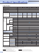
● Specification Type AE630-SW AE1000-SW AE1250-SW AE1600-SW 630 1000 1250 1600 (A) Frame size Rated insulation voltage (Ui) (AC.V) 1000 Rated operational voltage (Ue) (AC.V) 690 (kV) 12 Rated impulse withstand voltage (Uimp) Pollution degree 3 Number of poles 3, 4 Rated current In (CT rating) ( General use Current rating adjustable 0.5 to 1.0 × In 0.
AE2000-SWA AE2000-SW AE2500-SW AE3200-SW AE4000-SWA AE4000-SW AE5000-SW AE6300-SW 2000 2000 2500 3200 4000 4000 5000 6300 2000 2000 1000 1000 690 690 12 12 3 3 3, 4 3, 4 (HN, FN) (Note7) 2500 3200 4000 4000 1000-1100-1200-1300- 1000-1100-1200-1300- 1250-1375-1500-1625- 1600-1760-1920-2080- 2000-2200-2400-26001400-1500-1600-1700- 1400-1500-1600-1700- 1750-1875-2000-2125- 2240-2400-2560-2720- 2800-3000-3200-34001800-1900-2000 2250-2375-2500 1800-1900-2000 (Note 5) 2880-3040-320
Over view (AE630~1600-SW, AE2000~3200-SW) Connections Type Horizontal Standard Vertical (VT) Front (FT) Vertical terminal adapter (VTA) Front terminal adapter (FTA) FIX-VTA FIX-FTA DR-VTA DR-FTA Fixed type (FIX) Drawout type (DR) DR-VT DR-FT ● Connection image : AE630~1600-SW, 3-pole type Over view (AE2000-SWA, AE4000-SWA, AE4000~6300-SW) Connections Vertical (VT) Type Standard Fixed type (FIX) FIX-VT Drawout type (DR) DR-VT ● Connection image : AE2000-SWA, 3-pole type ● For AE2000-SW
Manual charging The closing spring is charged by the manual charging handle. The breaker is closed when the ON button is pressed, and opened when the OFF button is pressed. ● When the closing spring is completely charged, the charging indicator will show "CHARGED". ● The indicator shows the ON or OFF state of the main contacts. ● The breaker cannot be closed while the OFF button is being pressed. (Safety feature) ● OFF lock is available by padlock (See P7, P17) as standard.
2 3 6 5 4 4 7 1 9 8 Closing coil (CC) 2 The closing coil is a device to close the breaker by remote control. ● An interlock to prevent pumping is provided electrically. Rated voltage (Applicable voltage range) Operating voltage • Operating inrush current (VA) DC24-48V (18~52.8) AC • DC common 100-250V (75-275) AC DC – DC24V 3.0A (100W) – CC circuit diagram Closing time (Note1) Breaker Min. 80ms CC unit A1 DC48V 6.0A (200W) AC100V 0.7A (100VA) DC100V 0.8A (100W) AC250V 1.
Under voltage trip device (UVT) 4 This is the device that automatically trips the breaker when the circuit voltage drops below the nominal voltage, and comprises UVT coil and UVT controller. There are 3 kinds of tripping time, INST, 0.5s and 3.0s.
Push button cover (BC-L) 7 The cover prevents careless manual operation (ON,OFF) of the push buttons. BC-L can be locked by a padlock (The padlock should be supplied by the customer.) For the suitable size of a padlock, refer to Page 17. Cylinder lock(CYL) 8 The breaker is locked OFF with the cylinder lock. ● Since it is an interlock which only allows the key to be removed when the breaker is locked off, it can be used for interlocking two or more breakers.
Mechanical interlock (MI) This is the device to prevent parallel charge of 2 or 3 units of breakers, and it can interlock the breakers mechanically without fail. All combinations are available among any models from AE630-SW to AE4000-SWA. Please make inquiries about installation to AE4000-SW~AE6300-SW. Further the interlock is possible among the different connection types or poles, such as fixed type or drawout type, 3 pole or 4 pole.
Drawout interlock (standard) This is the safety device that prevents insertion and drawout operation. When the breaker is ON, the drawout handle cannot be inserted, and insertion and drawout operation cannot be done unless the OFF button is pressed. 2 Position lock (standard) This is the device that locks automatically the drawout mechanism at "TEST" or "CONNECTED" positions during insertion and drawout operation. When the lock plate is pushed in, lock is released and operation can be continued.
Cell switch (CL) This is the switch to show the drawout position (CONNECTED, TEST, and DISCONNECTED) of the breaker. An arbitrary combination up to 4 pieces is available. Operating sequence Switch rating Drawout position of breaker Disconnected DISCON CL-C (CONNECTED) CL-T (TEST) CL-D (DISCONNECTED) TEST CONNECT OFF ON 2.5 10 10 250 3 1.5 125 10 6 30 10 10 125 ON DC OFF Note 1: The setting is available for change by customer later.
3 Power supply module This module provides control source for DISPLAY module,Trip indicator and several indicators (LEDs). (Even when the control power source is off, the function of over current protection and ground fault protection are effective.) There are two types of power supply modules, one is only of power supply function, the other is power supply function with output contact (6 contacts). A D B 1 Main setting module This module provides the function of over current protection.
Characteristic table NA G1 E1 AP N5 Nothing Ground fault Earth leakage 2nd additional Pre-alarm Neutral pole 50% protection 2 1 WS General use LTD+STD+ INST/MCR WM Generator protection use LTD+STD+ INST/MCR WB Special use INST/MCR Power supply module Type 100-240V P1 3 Contact capacity(Type code P3, P4) Rating alarm output Current (A) Nothing AC•DC 24-60V DC Nothing P3 100-240V AC 100-125V DC 6 output contacts P4 24-60V DC 6 output contacts P5 100-240V DC 6 output contacts
A Trip indicator LED B Pre-alarm LED C Temperature alarm LED D Load current LED E RUN LED F ERR. LED G G Current setting dial L H Uninterrupted current setting dial D I LTD time setting dial E H J STD pick-up setting dial I K STD time setting dial L INST/MCR pick-up current setting dial F J M Optional setting module (P.27~29) B N Pre-alarm current setting dial O RESET button (TEST L/S LOCK button) K A P TEST terminal C M Note: The figure shown WS type with G1 plug. G1 is option.
■Operating characteristic curve (for general use : WS) 5000 (h) 4000 1 3000 40 2000 30 20 1000 PAL current : Ip Iu x 0.68~1.0(0.04step)-OVER ±10% 15 10 Uninterrupted current : Iu 0.8~1.0 x Ir(0.02step) … LTD Pick-up 1.05 x Iu…Non pick-up 1.25 x Iu Pick-up 500 400 300 8 (min) 6 4 200 2 LTD time : TL 12-25-50-100-150(s) ±20% (at Iu x 2) 100 60 50 40 40 30 30 20 operating time (s) 1 50 20 PAL time : Tp TL/2 ±20%(at Iu x 2) 10 10 STD pick-up current : Isd Ir x 1.5-2-2.
A Trip indicator LED B Pre-alarm LED C Temperature alarm LED D Load current LED E RUN LED F ERR. LED K G LTD pick-up current D H LTD time setting dial I STD pick-up setting dial E J STD time setting dial G K INST/MCR pick-up current setting dial F L Optional setting module (P.27~29) H M Pre-alarm current setting dial I B N RESET button (TEST L/S LOCK button) O TEST terminal A J Note: The figure shown WM1 type with G1 plug and Display (DP1). G1 and DP1 are options.
■Operating characteristic curve (for generator protection use : WM) 5000 (h) 4000 1 3000 40 2000 30 20 Pre-alarm current : Ip IL x 0.68 0.68~~1.0(0.04step) 1.0(0.04step)±10% ±5% 1000 15 10 500 LTD pick-up current : IL 1.0-1.05-1.1-1.15-1.2 ±5% Factory setting position is 1.15 400 300 8 (min) 6 4 200 2 100 60 LTD time : TL 15-20-25-30-40-60(s) ±20% (at IL x 1.2) 50 operating time (s) 40 1 50 40 30 30 20 20 Pre-alarm time : Tp TL/2 ±20%(at IL x 1.
A Trip indicator LED B Pre-alarm LED C Temperature alarm LED D D Load current LED G E RUN LED E F ERR. LED G Current setting dial F H INST/MCR pick-up current setting dial H I Pre-alarm current setting dial B J RESET button A K TEST terminal C Relation of setting dial In (CT rating) J K Ir Ii Ig (P.27) Ip Ip2 (P.29) Load current LED (60, 80, 100%, OVER) I Adjustable setting range No. Setting item G Current setting Mark Ir Adjustable setting range 0.5 ~ 1.0 (0.
■Operating characteristic curve (for special use : WB) 5000 (h) 4000 1 3000 40 2000 30 20 1000 15 10 Pre-alarm current: Ip Ir x 0.68 ~ 1.0(0.04step)-OVER ±10% 500 400 Max. time of let-through current 8 6 Pre-alarm time: Tp 75s ±20% at Ir x 2 300 200 (min) 4 2 Max.
Accessories Ground fault protection(GFR) The ground fault protection (GFR) of several hundred amperes is possible. This function can be selected for trip and alarm (no trip). Power supply is necessary for this function, even if there is not power supply, it can function at 0.2xIn or higher. Mark Adjustable setting range Setting item Accuracy Factory default value ±20% 1.0 GFR pick-up current Ig 0.1-0.2-0.3-0.4-0.5-0.6-0.7-0.8-0.9-1.0 x In GFR time 3-1.5-0.8-0.5-0.3-0.15-<0.1 - <0.1-0.15-0.3-0.5-0.
Earth leakage protection(ER) By combining the ETR with earth leakage protection (ER) and External ZCT, earth leakage protection is possible. Earth leakage protection, earth leakage tripping and earth leakage alarm can be selected. Control supply is necessary for this function. Mark Adjustable setting range Accuracy Factory default value ER pick-up current IΔn 1A-2A-3A-5A-10A +0% –30% 10A ER time 3-1.5-0.8-0.5-0.3-0.15-<0.1 - <0.1-0.15-0.3-0.5-0.8-1.5-3s ±20% 3s (TRIP) TRIP ALARM (at 1.
Accessories 2nd Additional Pre-alarm (AP) The Pre-Alarm (1st) function already installed in standard breaker, the 2nd additional Pre-Alarm function can be installed as option, thereby it is possible to monitor (observer) electric circuit in more detail by 2nd additional Pre-Alarm function. Setting item Mark 2nd Additional Pre-alarm pick-up current Ip2 2nd Additional Pre-alarm time Tp2 Adjustable setting range Accuracy Factory default value 0.5-0.6-0.7-0.8-0.84-0.88-0.92-0.96-1.0 x Iu WS ±10% WS 0.
MCR switch (MCR-SW) If MCR switch is built in the breaker and the dial for INST/MCR on Main setting module is set to the range of MCR position, MCR function is operative. MCR function: During a closing operation of the breaker, Instantaneous characteristics is operative. And it becomes inoperative when the breaker is in the closed position. Temperature alarm (TAL) If TAL sensor is built in the breaker, temperature alarm is operative.
Additional functions By adding the extension module unit in ETR, additional functions like measuring, display and communication become available.
Extension module (EX1) This is the base module that provides various additional functions with combining Display module (DP1 / DP2), Interface unit (BIF-CC / BIF-PR / BIF-MD) and VT unit (VT). 1 Various measuring elements, high measuring accuracy By adopting high-performance ASIC, various measuring elememts (load current, voltage, energy, harmonics, etc.) and high measuring accuracy are attained. Refer to page 34 for more details.
Network Interface unit (BIF-CC/BIF-PR/BIF-MD) These Interface units can expand the future possibility in various communication and Intelligent control. 2 1 Applicable to various open networks. These units are applicable to various open network systems such as CC-Link®, PROFIBUS-DP and MODBUS® (RS-485), which can be built in easily.
: can be displayed by DP1/DP2 : can be displayed and set by DP1/DP2 + Combination sample ➀ Type ➀Main setting module WS ➁ - ➂ + + Note 1) ;EX1;DP1(;DP2) WM WB ➀ WS ➁ - ➂ Note 1) ;EX1;DP1(;DP2),VT WB WM ➁Optional setting module NA AP G1 E1 NA AP G1 E1 NA AP G1 E1 NA AP G1 E1 NA AP G1 E1 NA AP G1 E1 ➂Power supply P1~P5 P1~P5 Measurement Load current (±2.5%) Leakage current (±15%) Note 4) Voltage (±2.5%) Power (active,reactive,apparent) (±2.
Electronic trip relay circuit diagram Upper side terminal Electronic trip relay (ETR) Trip coil ➅ Power supply circuit Rectifier circuit V1+ 0V ➄ Microprocessor ➃ ASIC Constant voltage circuit Setting input ➆ Trigger circuit Power supply CT V2+ Load current LED 60-80-100-OVER PAL LED CPU N1 N2 Z1 Z2 Ground fault Integration/ composition circuit and Earth leakage circuit Test connector W.D.T.
Setting procedure 1 Prepare a small flat tipped screwdriver. 0.8mm max. 6mm max. Press the screwdriver in the direction of the arrow to open the cover Side view of the flat tip ETR cover 2 Insert the flat tipped screwdriver into the opening of the ETR cover. Then, lightly turn the screwdriver to the upside as shown in the left figure, and the ETR cover will open. Sealing hole Operating hole for resetting 3 There are two kinds of switches for characteristics setting and for trip indicator reset.
Reset circuit Power circuit 564 554 544 534 524 STD/INST LTD FG Dielectric test forbidden Electronic trip relay Control power circuit / alarm contact Terminal description 14 ~ 53 54 Auxiliary switch "a" 11 12 ~ 51 52 Auxiliary switch "b" U1 U2 Motor charging 413 414 Charged signal Voltage Input terminal of UVT D1 D2 DT2 A1 A2 Closing coil C2 Shunt trip 97 98 OCR alarm P2 RS1 Power supply for ETR FG of power supply (FG:Frame Ground) P4 RS2 U1 CC M 98 C2 A2 DT
Breaker 43 33 23 13 42 32 22 12 54 44 Breaker Auxiliary switch(normal close) 380-460V AC type input IN2 + D1 14 344 342 334 332 324 CL 311 322 314 312 Cell switch Cell switch Note; input D2 24 Auxiliary switch(normal open) Fig.
Drawout type AE630-SW,AE1000-SW, AE1250-SW, AE1600-SW (mm) Side view Front face of control terminal 4P Horizontal (standard) terminal *200 149 48 368 Fully drawout position 15 Earth terminal M8 screw 23 *220 452 234(149) 172 40 Panel 4-φ14 15 53 25 40 15 15 50 15 42.
Drawout type AE2000-SWA (mm) Front view Side view Operating panel center 150 235(150) Control terminal (M3.5 screw) Front face of control terminal Disconnected 54 Test 35 228 Lifting hook hole 283 3P 4P 370 57 100 340 430 Aperture for the drawout handle 157 Neutral pole *200 149 40 Panel 4-ø14 48 452 234(149) Fully drawout position * : Mounting pitch The numerals shown in parentheses are for 3 poles. 100 172 *220 29.5 25 40 42.
Drawout type AE2000-SW, AE2500-SW, AE3200-SW (mm) Front view Side view Operating panel center Control terminal (M3.5 screw) Front face of control terminal Disconnected 54 324(194) 368 61 366 Fully drawout position T 83 Earth terminal M8 screw Dimensions 23 *220 452 Inside of the panel (thickness 1.6~3.2) * : Mounting pitch The numerals shown in parentheses are for 3 poles.
Drawout type AE4000-SWA (mm) Front view Side view Operating panel center Control terminal (M3.5 screw) Front face of control terminal Lifting hook hole Disconnected 54 325(195) Test 35 228 Connecting busbar size All poles: T10xW150x4BUS/pole 283 Neutral pole 25 40 67 15 15 42.5 *200 Panel 4-φ14 Earth terminal M8 screw 23 368 109 366 Fully drawout position * : Mounting pitch The numerals shown in parentheses are for 3 poles.
Drawout type AE4000-SW, AE5000-SW, AE6300-SW (mm) Front view Side view Neutral pole Control terminals (M3.5 screw) 588.5(458.5) Operating panel center 373.5 28 228 Front face of control terminal Disconnected 54 28 Test 35 4P HN 3P Lifting hook hole M12 Weld nut 283 Mounting angle Fixing bolts 2-M12 Panel 42.5 4-M12 *530 395 172 * : Mounting pitch The numerals shown in parentheses are for 3 poles.
Fixed type AE630-SW, AE1000-SW, AE1250-SW, AE1600-SW (mm) Front view Side view Operating panel center 142 227(142) 275 3P 93.5 Control terminal (M3.5 screw) 139 4P 15 132 5 72 4-φ14 410 340 7 350 15 Neutral pole Earth terminal M8 screw (Left side) 228 *156 170 Panel 40 *175 *241(156) 290 255(170) 288 * : Mounting pitch The numerals shown in parentheses are for 3 poles. Inside of the panel (thickness 1.6~3.
Fixed type AE2000-SWA (mm) Front view Side view Operating panel center 142 227(142) 93.5 Control terminal (M3.5 screw) 275 3P 139 4P 410 350 340 57 100 7 157 Neutral pole 228 *156 *241(156) 170 *175 Panel 290 255(170) 24.5 40 5 Earth terminal M8 screw (Left side) 31 108 288 * : Mounting pitch The numerals shown in parentheses are for 3 poles. Inside of the panel (thickness 1.6~3.
Fixed type AE2000-SW, AE2500-SW, AE3200-SW (mm) Front view Side view Operating panel center Control terminal (M3.5 screw) 317(187) 232 93.5 139 275 132 20 4-φ14 40 5 Earth terminal M8 screw (Left side) 228 *246 *175 Panel *331(201) 260 290 345(215) 288 * : Mounting pitch The numerals shown in parentheses are for 3 poles. Inside of the panel (thickness 1.6~3.
Fixed type AE4000-SWA (mm) Front view Side view Operating panel center 232 Control terminal (M3.5 screw) 317(187) 93.5 275 Connecting busbar size All poles: T10xW150x3BUS/pole 139 Neutral pole 4P 410 182 340 57 7 350 125 3P 228 Panel *246 *175 *331(201) 290 345(215) 260 4.5 40 5 Earth terminal M8 screw (Left side) 67 129.5 4-φ14 31 117 Earth terminal M8 screw (Left side) 288 * : Mounting pitch The numerals shown in parentheses are for 3 poles.
Fixed type AE4000-SW, AE5000-SW, AE6300-SW (mm) Front view Side view Control terminals (M3.5 screw) Neutral pole 581.5(451.5) Bus bar 275 93.5 139 4P HN 354 57 7 182 340 125 3P 14 or more 366.5 414 Operating panel center 4-φ14 9 228 *595.5(465.5) *175 Panel 290 609.5(479.5) 394.5 10 40 *380.5 31 Earth terminal M8 screw (Left side) 136 288 * : Mounting pitch The numerals shown in parentheses are for 3 poles. Inside of the panel (thickness 1.6~3.
Panel cut-out, Drawout handle, Terminal adapter Panel cut-out dimensions Door frame panel cut-out dimensions Panel cut-out dimensions 7.
Neutral CT (NCT), External ZCT Neutral CT (NCT) M5 screw 2500~4000A 630~2000A 162 4 68 M5 screw 160 51 219 5.5 105 137 97 R2 28 9 31 16.5 R3 122 Mounting pitch 38 142 66 11 48 Slit for M8 screw 192 Mounting pitch 55 Slit for M10 screw 212 87 External ZCT for transformer ground wire Terminals M3.5 screw A Terminals M3.5 screw F 30 28 E 12 D C B 3 2 C G B D 7.
UVT external unit UVT external unit (AC380 ~ 460V) 30 30 20~24 Mounting bracket Height of wiring Terminal IN1 IN2 OUT OUT 4 3 (mm) Use the attached mounting bracket. (Not applicable to 35mm IEC rail) Terminal 117 107 100 UVT external unit IN1 380-460V AC OUT4 To AE-SW terminals of UVT controller 65 30 IN2 30 Mounting ø4.5 hole 90 OUT3 ETR external units Display onto panel board (DP2) (mm) Operation display surface 64 48 Panel (Note) 42 16 Note : Use the panel of thickness 1mm ~ 3.
I/O unit (BIF-CON) 100 77.5 30 30 Mounting bracket 5 90 35 Terminal 117 107 IEC35mm rail 23.5 37.5 67.5 35mm IEC rail holder 65 Terminal 30 30 Input M3 terminal screws Mounting φ4.5 hole K12 K22 K32 K11 C2 C1 A2 A1 U2 U1 35mm IEC rail holder Shunt trip (SHT) Closing coil (CC) Motor charging (MD) PROFIBUS-DP interface unit (BIF-PR) 100 77.5 30 30 Mounting bracket 5 Terminal 90 35 107 117 IEC35mm rail 23.5 67.5 37.
Pre-cautions when making connections Use M12 bolts, plain washers, and spring lock washers to connect the conductor. There are various size plain washers, but use 24mm or smaller outside diameter washers. The washers may overlap if too large washers are used. It is recommended to apply silver plating on the contact surface of the conductor which is used to connect with the terminal of circuit breakers in order to prevent the increase of contact resistance due to moisture, etc.
Insulation distance When a short-circuit current is interrupted, discharged hot gas blows out from the exhaust port of the arc extinguishing chamber, so provide a clearance as shown in the following table. Note1:On the fixed type, maintenance is possible with following clearance.
Internal resistance, reactance and power consumption (per pole) Type Connection Internal resistance (mΩ) Reactance (mΩ) Power consumption (W) Fixed type 0.028 0.059 11 Drawout type 0.042 0.089 17 Fixed type 0.026 0.060 26 Drawout type 0.040 0.091 40 Fixed type 0.024 0.060 38 Drawout type 0.038 0.091 60 Fixed type 0.016 0.063 41 Drawout type 0.030 0.095 77 Fixed type 0.016 0.063 64 Drawout type 0.025 0.095 100 Fixed type 0.010 0.047 40 Drawout type 0.020 0.
Deratings by ambient temperature (A) IEC60947-2, BS, JIS C 8201-2-1 (Standard:40°C) Standard LR, GL, BV, DNV, ABS, NK, CCS (Standard:45°C) Ambient Temperature 40°C 45°C 50°C 55°C 60°C AE630-SW 630 630 630 630 630 AE1000-SW 1000 1000 1000 1000 1000 AE1250-SW 1250 1250 1250 1250 1200 AE1600-SW 1600 1600 1600 1550 1500 AE2000-SWA 2000 2000 1900 1800 1700 AE2000-SW 2000 2000 2000 2000 2000 AE2500-SW 2500 2500 2500 2450 2350 AE3200-SW 3200 3200 3200 3000 29
Discrimination table AE-SW Series air circuit breakers provide easy selective co-ordination with branch circuit breakers. For selective co-crdinations,refer to the following table.
AC440V sym kA Main circuit breaker ng c apa Branch city circuit breaker Un it b rea ki NF | S • H • MB • NV | S • H NF | C • NV | C NF | U NF32-SW MB30-SW MB50-CW NV32-SW NF63-SW MB50-SW NV63-SW NF63-HW NV63-HW NF125-SW MB100-SW NV125-SW NF125-HW NV125-HW NF250-SW MB225-SW NV250-SW NV250-SEW NF250-HW NV250-HW NF400-SW NV400-SW NF400-SEW NV400-SEW NF400-HEW NV400-HEW NF400-REW NV400-REW NF630-SW NV630-SW NF630-SEW NV630-SEW NF630-HEW NV630-HEW NF630-REW NF800-SEW NV800-SEW NF800-HEW NV800-HEW NF800-
Ordering information for Mitsubishi AE-SW series air circuit breaker(General use....WS Type, Special use....WB Type) Customer(name) Type P9~10 Order No. AE -SW Number of poles AE 4P 3P AE4000-SW~ AE6300-SW AE630-SW~ AE4000-SWA Current setting Ir A IEC 60947-2 CCC Ambient temperature 40°C(Standard) Others Automatic Reset (Standard) Connection Fixed type Main circuit terminal Horizontal terminal(FIX) P.
Ordering information for Mitsubishi AE-SW series air circuit breaker(General use....WS Type, Special use....WB Type) Customer(name) Type P.9~10 Order No. AE -SW Number of poles AE 4P 3P AE4000-SW~ AE6300-SW AE630-SW~ AE4000-SWA Current setting Ir A IEC 60947-2 CCC Ambient temperature 40°C(Standard) Others Automatic Reset (Standard) Connection Fixed type Main circuit terminal Horizontal terminal(FIX) P.
Ordering information for Mitsubishi AE-SW series air circuit breaker(Generator protection use....WM Type) Customer(name) Type Order No. AE P.9~10 -SW Number of poles AE 4P 3P AE630-SW~ AE4000-SWA Current setting Ir AE4000-SW~ AE6300-SW LR GL BV Ambient temperature 40°C(Standard) DNV 4P HN 4P FN 3P Automatic Reset (Standard) Connection Fixed type Note15 Note15 Main circuit terminal Horizontal terminal(FIX) (AE630~1600-SW / AE2000~3200-SW) Vertical terminal(FIX-VT) ( ) CCS P.
Country / Region Company Address Telephone Australia Mitsubishi Electric Australia Pty. Ltd. 348 Victoria Road, Rydalmere, N.S.W. 2116, Australia + 61-2-9684-7777 Belgium Koning & Hartman B.V. Woluwelaan 31, BE-1800 Vilvoorde, Belgium + 32-(0)2-2570240 Vte. Agua Santa 4211 Casilla 30-D (P.O. Box) Vina del Mar, Chile (Shanghai) 3F, Block 5, 103, Cao Bao Road, Shanghai, China + 56-32-2-320-600 Chile Rhona S.A.
Safety Tips : Be sure to read the instruction manual fully before using this product. HEAD OFFICE: TOKYO BUILDING, 2-7-3 MARUNOUCHI, CHIYODA-KU, TOKYO 100-8310, JAPAN. Y-0622E 0706 (MDOC) Revised publication, effective June 2007. Specifications subject to change without notice. This pamphlet is made from recycled paper.