December 2021 LOSSNAY ENERGY RECOVERY VENTILATOR HANDBOOK MODELS LGH-F300RVX2-E LGH-F380RVX2-E LGH-F470RVX2-E LGH-F600RVX2-E LGH-F940RVX2-E LGH-F1200RVX2-E Nameplate Nameplate Remote controller (Optional) PZ-62DR-EA PZ-43SMF-E Filter (For replacement) PZ-50RF9-E PZ-65RF9-E PZ-80RF9-E PZ-100RF9-E Warning: Repair work must be performed by the manufacturer, its service agent or a similarly qualified person in order to avoid hazards. No.
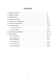
Contents 1. Safety precautions...........................................................................33 2. Changed points................................................................................44 3. Specifications...................................................................................4-5 4 4. Outside dimensions.........................................................................6-8 6 5. Electrical wiring diagrams................................................................
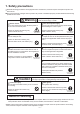
1. Safety precautions ead the following precautions thoroughly before the maintenance, and then inspect and repair the product in a R safe manner. The types and levels of danger that may arise if the product is handled improperly are described with the warning symbols shown below. Warning Improper handling of the product may result in serious injury or death. Electric shock If you must inspect the circuitry while the power is on, do not touch the live parts.
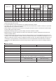
2. Changed points New model LGH-F300RVX2-E Former model LGH-F300RVX-E LGH-F380RVX2-E – LGH-F470RVX2-E LGH-F470RVX-E LGH-F600RVX2-E LGH-F600RVX-E LGH-F940RVX2-E Changes from the former model • Filter grade was changed from MERV4 to MERV7. • New control circuit board – LGH-F1200RVX2-E LGH-F1200RVX-E PZ-62DR-EA PZ-61DR-E 3.
Model name Input power (W) Air volume Specific Fan power Static pressure (CFM) (CMH) (W/CFM) (InH2O) (Pa) Exchange efficiency (%) Enthalpy Temperature Heating Cooling Noise (dB) Dia. of the Weight centrifugal fan (Inch (mm)) (lbs) (kg) LGH-F300RVX2-E 235 300 510 0.78 1.00 250 65.5 63.0 50.0 37.0 8 3/4 (220) 75 34 LGH-F380RVX2-E 340 380 646 0.89 0.86 215 65.0 61.0 49.0 38.0 9 5/8 (245) 90 41 LGH-F470RVX2-E 425 470 799 0.91 1.00 250 69.0 64.0 51.0 40.
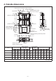
4. Outside dimensions LGH-F300RVX2-E, LGH-F380RVX2-E, LGH-F470RVX2-E, LGH-F600RVX2-E Position where duct direction change is possible By-pass damper plate L Ceiling suspension fixture (4-1/2 X 13/16 (4-13 X 20) oval) D K Air exhaust fan RA (return air) OA (outside air intake) 13/16 (20) Inspection opening 1.5 x 1.
LGH-F940RVX2-E, LGH-F1200RVX2-E By-pass damper plate Air exhaust fan 1 1/32 (26) 5 7/8 to 9 7/8 (150 to 250) Inspection opening 1.5 x 1.
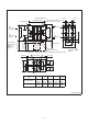
PZ-62DR-EA PZ-43SMF-E 3/4 (19) 19/32 (15) 4 23/32 (120) 4 23/32 (120) 2 3/4 (70) 4 22/32 (120) Unit: Inch (mm) PZ-50RF9-E, PZ-65RF9-E, PZ-80RF9-E, PZ-100RF9-E The number of filters per set Dimension Model A B C 18 1/2 (470) 17 3/64 (433) 7 13/64 (183) 8 37/64 (218) 25/32 (20) 25/32 (20) PZ-80RF9-E 17 3/4 (451) 9 9/16 (243) PZ-100RF9-E 22 1/4 (565) 9 9/16 (243) PZ-50RF9-E PZ-65RF9-E Unit: Inch (mm) Applicable model Supply Exhaust 2 2 LGH-F300RVX2-E 2 2 LGH-F380RVX2-E 25/32 (
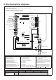
5. Electrical wiring diagrams LGH-F300RVX2-E, LGH-F380RVX2-E, LGH-F470RVX2-E, LGH-F600RVX2-E * Wiring for TM1, TM2, TM3, TM4, and TB5 shown in dotted lines are field work. * Be sure to connect the earth wire. * An all pole electric leakage isolator must be installed. * Always use an isolator for the main power connection. Lossnay unit Control circuit board Monitor output PZ-62DR-EA 2nd remote controller (Max. 2 controllers) 2nd Lossnay unit (Max.
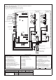
LGH-F940RVX2-E, LGH-F1200RVX2-E * Wiring for TM1, TM2, TM3, TM4, and TB5 shown in dotted lines are field work. * Be sure to connect the earth wire. * An all pole electric leakage isolator must be installed. * Always use an isolator for the main power connection. Lossnay unit Power circuit board (Lower unit) Control circuit board Monitor output PZ-62DR-EA 2nd remote controller (Max. 2 controllers) 2nd Lossnay unit (Max. 15 units) M-NET transmission cable Shielded Wire 12 V or 24 V DC Mr.
6. Circuit board diagrams Circuit board diagrams and check points (1) Control circuit board Caution: Before servicing (including replacing the circuit boards), be sure to turn off the power supply isolator and check that all the LEDs on the control circuit board and power circuit board are not lit. A largecapacity electrolytic capacitor on the circuit board may carry voltage for several minutes after the isolator is turned off.
(2) Power circuit board There are three types of the power circuit board. The type of the power circuit board varies depending on the model of the Lossnay unit. When replacing the circuit board, use the applicable circuit board according to the table below.
7. Troubleshooting Work precautions • Before starting the service, the power supply isolator must be turned off. Pay sufficient attention to avoid electric shock or injury. hen removing or touching the cables, circuit boards or other parts, be sure to turn off the power supply isolator. •W •E ven after the power supply isolator is turned off, the capacitor on the circuit board retains high voltage for a while.
(1) Failure mode 1: Lossnay does not work. Lossnay does not start properly. Lossnay does not work in trial operation, or Lossnay stops working during use. The remote controller does not work. (2) Failure mode 2: The remote controller does not work. Operations such as ON/OFF, fan speed or ventilation mode switching are not possible on the remote controller. (3) Failure mode 3: Operations on the remote controller are not possible. • An error code is displayed on the remote controller.
[2] Transmission cables (remote controller transmission cable, M-NET transmission cable, external input/output signal cable, and connection cable for IT communication appliances) No. Check Item Corrective action 1 Are the designated cables used for the remote controller transmission cable and M-NET transmission cable? (See Table 2-1 and Table 2-2.) 2 Are the designated cables used for the external input/ output signal cable? (See Table 2-3.
Table 2-3 External input/output specifications Function Name External control input (volt-free contact) (Note 4) External control input (12 V DC, 24 V DC) (Note 4) Terminal or Signal connector on specifications the circuit board Level/pulse TM2 [Y] [Z] (Note 1) Level/pulse TM2 [1] [2] (Note 1) Mr.
[3] Monitor output signal cable No. Check Item Corrective action 1 Is the signal cable wired by multicore cable? Wire the cable using a 2-core cable. 2 Are the signal cables and transmission cables wired in the same piping duct? 3 Is the power supply cable wired at least 2 in. (5 cm) away from signal cables? 4 Is the signal cable connected to the designated terminal block? (See Table 3-1.
[5] LED Indications on the circuit boards No. 1 2 LED Contents Check Item Corrective action LED1 Lossnay unit error Blinking: Starting up, error occurred In the case of an error, see Failure (green) indicator Mode 4. Lit: During delay operation Lossnay operates after the delay time has passed.
Individual function check items [6] If Lossnay does not work in the trial operation, or if Lossnay stops working during use, check the following items. No. Problem Factor Corrective action 1 The fan does not The connectors between the operate even fan motor and circuit board are though the trial disconnected. operation switch (SW2-1) on the circuit board is turned ON. The connectors between the control circuit board and power circuit board are disconnected.
No. Problem 3 [When wall-mounted type CO2 sensor PZ-70CSW-E is used] The LED display lamps of the CO2 sensor do not light even though the trial operation switch (SW2-1) on the Lossnay circuit board is turned ON. Factor Corrective action CO2 sensor setting is set incorrectly. Check the setting. •W hen the function setting (No.
No. Problem 6 Even though the remote controller is operated to change the fan speed, the fan speed does not change. Factor Corrective action The indoor negative pressure setting or the indoor positive pressure setting is set. The external fan speed input is set. (CN17) The external fan speed input is set. (CN26) The system is operating in the protective mode (intermittent operation). Airflow setting is performed with PZ-62DR-EA. 7 The fan operation is The motor rotation speed is unstable.
No. Problem 10 Even though the remote controller is operated to change the ventilation mode, the ventilation mode is not changed. Factor Corrective action The outdoor temperature is 46.4°F (8°C) or lower. The signal is input to the Bypass mode switching input (CN26 [1] [2]). The Lossnay unit is performing the Night-purge operation. The pre-heater is ON, or within one hour after the pre-heater is turned OFF.
No. Problem 13 Actual fan speed of the Lossnay unit differs from the fan speed set with the remote controller. 14 The Night-purge operation cannot be stopped with PZ-62DR-EA. 15 Even though the Night-purge is set, Lossnay does not perform the Nightpurge operation. 16 The Night-purge operation stops in halfway through. 17 The Lossnay unit does not operate with the MELCloud application. (When the Wi-Fi interface is used) Factor Corrective action The signal is input to the fan speed input (CN17).
No. Problem 18 When the supply fan is stopped, the exhaust fan operates at the higher fan speed than the fan speed set with the remote controller. 19 Abnormal noise comes from the damper motor Factor Corrective action The Lossnay unit is operating in the protective mode (intermittent operation). (Outdoor temperature is 23°F (-5°C) or lower.) During the intermittent operation, the exhaust fan operates at fan speed 4.
Start Is the UNIT lamp on the Wi-Fi interface blinking? There is a problem in communication between the Lossnay and the Wi-Fi interface. No Yes [1] Read the QR code of the Wi-Fi interface, and check that the SERVICE REFERENCE is NOT "MAC-567IF-E". If the SERVICE REFERENCE is "MAC-567IF-E", the Wi-Fi interface does not support Lossnay. Replace the Wi-Fi interface with a one that supports Lossnay. (ex. MAC-567IF-E1 supports Lossnay.
(2) Failure mode 2: The remote controller does not work. If the remote controller does not work, check the following items. [1] PZ-62DR-EA No. Problem Factor Corrective action 1 Nothing is displayed on the remote controller. The ON/OFF lamp does not blink. The power of the Lossnay unit is not ON. Faulty connection of the remote controller transmission cable In one group, three or more PZ-62DR-EA controllers are connected. In one group, 16 or more Lossnay units are connected.
No. Problem 2 “H0” is displayed on the remote controller. 3 It takes time for the remote controller to be fed with power after turning the Lossnay unit ON. 4 The inspection number “6801” is displayed on the remote controller. Factor Corrective action The remote controller is starting up. The Lossnay unit is starting up.
Individual check items If the system cannot be started/stopped using the remote controller, check the following items. [1] PZ-62DR-EA No. Problem Factor 1 Some Lossnay units in The power of the Lossnay unit the group do not operate. is not ON. Faulty connection of the remote controller transmission cable The remote controller transmission cables are not correctly connected between the terminals (TM4 [1] [2]) of the Lossnay units in the group.
No. Problem Factor Corrective action 6 Even though the function The indoor, outdoor, and/or • Outdoor temperature display range: 35.6°F settings (No. 36, 37 and/ supply air temperature are out- (2°C) to 96.8°F (36°C) or 39) of PZ-62DR-EA are side the display range. • Indoor temperature display range: 48.2°F set to “1”, “LO” or “HI” is (9°C) to 98.6 °F (37°C) displayed on the remote • Calculated supply air temperature display controller. range: 48.2°F (9°C) to 98.
[2] Interlocking with air conditioners (Mr. Slim indoor unit or City Multi indoor unit) or external devices No. Problem 1 Lossnay interlock settings cannot be performed with the remote controller. Factor Corrective action The power of the Lossnay unit is not Check the items described in (1) [1]. ON. Faulty connection of the remote con- Check the items described in (1) [2]. troller transmission cable Lossnay address setting is incorrect. Check the Lossnay address.
[3] System controller No. Problem 1 The group of Lossnay cannot be set with the system controller. Factor Corrective action The power of the Lossnay unit is not ON. Check the items described in (1) [1]. M-NET transmission cable is connected to the remote controller terminal block (TM4 [1] [2]). Lossnay address setting is incorrect. Connect the M-NET transmission cable to the M-NET transmission cable terminal block (TB5 [A] [B]).
(4) Failure mode 4: Error code and LED display An error code displayed on the remote controller (PZ-62DR-EA, PZ-43SMF-E) or the M-NET controller, and blinking or illumination of LED1 (green) or LED2 (red) on the circuit board show the type of an error. The LED blink interval is 0.25 seconds for both on and off. The display duration is approximately 7 seconds. 0.25 s 0.25 s 0.
Error LED1 LED2 Symptom Code (green) (red) 4101 11 Overcurrent blinks error of the remote controller terminal 4116 1 blink or 6 blinks (*1) Abnormal rotation of the supply fan motor (Centrifugal fan does not work, insufficient motor speed, excessive motor speed, or rotation detected when operation is stopped) Cause Corrective action Shorting between the remote controller terminals The group contains two or more Lossnay units with the same address.
Error LED1 LED2 Symptom Code (green) (red) 4116 2 Abnormal blinks rotation of the or exhaust fan 7 motor blinks (Centrifugal fan (*2) does not work, insufficient motor speed, excessive motor speed, or rotation detected when operation is stopped) Cause Corrective action Faulty connection of the exhaust fan Check the connector (CN9) motor connector (CN9) on the power connection.
Error LED1 LED2 Symptom Code (green) (red) 5102 5 Return air blinks (RA) thermistor related error Cause Faulty connection of the thermistor connector (CN5) on the control circuit board Thermistor failure Corrective action Check the connector (CN5) connection. Disconnect the connector (CN5), and check the resistance of the thermistor. If the equivalent thermistor resistance differs greatly from the ambient temperatures, replace the thermistor.
Error LED1 LED2 Symptom Code (green) (red) 6602 2 Transmission blinks error (transmission processor hardware error) 6603 5 Transmission blinks error (transmission bus busy) Cause Corrective action Faulty connection of the M-NET transmission cable •W iring was performed with power still supplied to the M-NET transmission cable. •A ccidental communication error Check the items described in (1) [2]. Restart the system after completing wiring.
Error LED1 LED2 Symptom Code (green) (red) 6606 3 Transmission/ blinks reception error (communication error with transmission processor) 6607 Cause Corrective action Faulty connection of the M-NET transmission cable •W iring was performed with power still supplied to the M-NET transmission cable. •A ccidental communication error Check the items described in (1) [2]. Restart the system after completing wiring. If the error re-occurs, check for noise on the transmission cable.
Error LED1 LED2 Symptom Code (green) (red) 6831 9 PZ-62DR-EA blinks communication error (no reception) Cause Faulty connection of the PZ-62DR-EA transmission cable PZ-62DR-EA is connected to the terminals (TB5 [A] [B]).
(5) Temperatures and thermistor resistance table … … … Temperature Resistance (°F) (°C) value (kΩ) 100.4 102.2 104.0 105.8 107.6 109.4 111.2 113.0 114.8 116.6 118.4 120.2 122.0 38 39 40 41 42 43 44 45 46 47 48 49 50 3.1 3.0 2.9 2.8 2.7 2.6 2.5 2.5 2.4 2.3 2.2 2.2 2.1 … … Temperature Resistance Temperature Resistance (°F) (°C) value (kΩ) (°F) (°C) value (kΩ) 46.4 8 9.9 73.4 23 5.4 48.2 9 9.5 75.2 24 5.2 50.0 10 9.1 77.0 25 5.0 51.8 11 8.7 78.8 26 4.8 53.6 12 8.4 80.6 27 4.6 55.4 13 8.0 82.4 28 4.
8. Overhauling procedures Work precautions • When touching the electric components such as circuit boards and fan motors, do not touch the components for more than 5 minutes after power-off, and then start working. If LED4 on the circuit board is lit, do not touch the electric components. • Before replacing parts or components, follow the instructions described in the troubleshooting. • When servicing, always keep proper footing. • When servicing, be sure to turn off the power supply isolator.
(1) Turning power off [1] Shut down the unit. [2] Turn off the power supply isolator. Precaution When servicing, power supply to M-NET must be turned off. Live-line working may cause a circuit board failure. (2) Fan parts Control box cover [1] Remove the black screws (three special screws 4×8, indicated by ) to remove the control box cover. For LGH-F940RVX2-E and LGH-F1200RVX2-E See (5) [1] (on page 48) for removing the control box cover.
[4] Slide the fix piece to the left side. Fix piece [5] Pull out the hinge, and open the maintenance cover. Hinge Maintenance cover [6] Draw the Lossnay cores (with filters) from the main unit. Filter Lossnay core [7] Remove the screws (one special screw M4, indicated by ), and remove the core guides from the unit.
[8] Remove the separator. Separator [9] Remove the screws (Six PTT screws 5×10, indicated by For LGH-F300RVX2-E ), and draw the fan assembly out from the main unit. For LGH-F380RVX2-E to LGH-F1200RVX2-E Air supply fan assembly Air supply fan assembly *The figure shows LGH-F470RVX2-E. Assembly precaution When attaching the centrifugal fan, tighten the special nut to the specified tightening torque. Tightening torque for the special nut LGH-F300RVX2-E Special nut (M8) 3.43 ± 0.4 N.
(3) Terminal block parts [1] Remove the control box cover. → See (2) [1]. [2] Check that LED4 (red) on the control circuit board is OFF, and then disconnect the connectors (indicated by ) from the control circuit board. Control circuit board [3] Remove the screw (one PPT screw 4×20, indicated by ). LED4 CN14 CN5 CN19 CN7 Terminal block [4] Remove the screws (three PT screws 4×8, indicated by ), and remove the sub control base.
(4) Control parts (For LGH-F300RVX2-E to LGH-F600RVX2-E) Precaution Before replacing the circuit boards, see (6) Procedures for replacing the circuit boards (page 49). [1] Remove the control box cover. → See (2) [1]. [2] Check that LED4 (red) on the control circuit board is OFF, and then disconnect the connectors (indicated by ) from the control circuit board. Control circuit board LED4 CN14 CN19 CN5 CN7 [3] Remove the screws (two PT screws 4×8, indicated by ), and remove the control circuit board.
[5] Remove the screws (two PT screws 4x8, indicated by ), and slide the power circuit board to remove it. Power circuit board [6] Remove the sub control base. → See (3) [4]. [7] Disconnect the connectors (indicated by reactor. ) from the [8] Remove the screws (two PT screws 4×8, indicated by ), and remove the reactor.
(5) Control parts (For LGH-F940RVX2-E and LGH-F1200RVX2-E) Precaution Before replacing the circuit boards, see (6) Procedures for replacing the circuit boards (page 49). When removing only the control circuit board [1] Remove the black screws (three special screws 4×8, indicated by ) to remove the control cover. Control cover [2] Check that LED4 (red) on the circuit board is OFF, and then disconnect the connectors (indicated by ) from the control circuit board.
When removing the power circuit boards or reactors [1] Remove the screws (eight PT screws 4×8, indicated by ) to remove the control box cover. Control box cover [2] Remove the circuit boards and reactors. [Upper unit] a. Disconnect the connectors (indicated by Power circuit board (upper) Reactor ). Precaution When disconnecting the motor connectors, make sure that the power supply is turned off and all LEDs are unlit.
(6) Procedures for replacing the circuit boards Notes • Before removing the circuit boards for replacement, check the following Steps 1 and 2. • When the Lossnay remote controller PZ-62DR-EA is connected, be sure to replace the circuit boards as described in the Steps. Step 1 Details Check item Check the system configuration. Check if PZ-62DR-EA is connected to the circuit board to be replaced. The following describes settings required when replacing the circuit boards per the system configuration.
Step 4 Details Check item Removing the circuit boards • For the working precautions, see page 40. • For removing the circuit boards, see (4) Control parts (For LGH-F300RVX2-E to LGH-F600RVX2-E) (page 45) or (5) Control parts (For LGH-F940RVX2-E and LGH-F1200RVX2-E) (page 47). 5 Attaching the circuit boards [1] According to the function status record data prepared in Step 3, set the address setting switches, function selection switches, and model selection switch of the new circuit board. a.
Step 6 Details Check item Function setting with PZ-62DR-EA When PZ-62DR-EA is connected, according to the function status record data prepared in Step 2, set the function settings with PZ-62DR-EA. If PZ-62DR-EA is not connected, skip this step and proceed to Step 7. To perform function settings with PZ-62DR-EA, see the Lossnay Operating/ Installation Instructions or PZ-62DR-E Instruction Book.
(8) Setting status record [1] Basic information Date: Installation location: Model name: LGH-F ( 300 . 380 . 470 . 600 . 940 . 1200 ) RVX2-E Serial number on the nameplate (eight-digit): Address setting: Lot number marked on the circuit board: Microcomputer software version marked on the circuit board: Lossnay remote controller: ( Used . Not used ) Model name: ( PZ-62DR-EA . PZ-43SMF-E ) Interlocking with City Multi: ( Set . Not set ) Interlocking with Mr. Slim: ( Set .
[3] Function settings Enter the setting data of the functions set with PZ-62DR-EA. Function No. Setting Data Function No. Setting Data Function No. Setting Data Function No.
9. Parts catalog Please note the following when using the parts catalog. 1. When ordering parts, the part number, part name, and the number of parts are required. 2. It may take time for you to receive the parts. Make an inquiry about a rush order. 3. Specifications may be subject to change without notice. 4. Parts marked with and are critical for safety. 5. To maintain safety and performance, use the parts specified in the parts catalog. 6.
LGH-F300RVX2-E 16 16 17 a (4 pcs.) b c b (4 pcs.) 11 (2 pcs.) 15 (4 pcs.) b a 14 13 c 6 6 6 6 12 11 (4 pcs.) b c 12 a 10 5 4 9 16 5 9 3 2 b (2 pcs.) 7 8 16 b (4 pcs.) 5 c 6 4 6 (4 pcs.) b 17 (2 pcs.) d a 20 6 2 5 6 21 1 19 18 b 16 pcs. c 4 pcs. Screw cap 6 pcs. Symbol Screw name a PT screw 6x12 b PTT screw 4x8 c PT screw 5x10 d PTT screw 4x6 shows accessory parts.
LGH-F300RVX2-E No. 1 2 3 4 5 6 7 8 9 10 11 12 13 14 15 16 17 18 19 20 21 Name of part Maintenance cover Special screw M4 Core guide L Lossnay core Filter Filter stopper Core guide R Fix piece Lead support Hinge Cover Hanger L Fix piece Special screw 4x8 Special screw 4x8 Flange Hanger R GM assembly Rod Pull spring Screws in bag Parts No.
Air exhaust fan assembly 31 33 32 34 35 b e (2 pcs.) e (2 pcs.) 37 (4 pcs.) e 36 e (4 pcs.) 37 (4 pcs.) e e (4 pcs.
LGH-F300RVX2-E No. 31 32 33 34 35 36 37 38 39 Name of part Special nut (M8) Tab washer Centrifugal fan Special washer (10) Air guide DC motor (EA) Motor fix plate DC motor (SA) Separator Parts No. Q'ty pcs/unit W00 000 121 W00 000 134 W50 013 481 W50 003 478 W50 013 508 W50 023 454 W50 013 723 W50 023 453 W50 013 486 2 2 2 2 2 1 2 1 2 ─58─ Critical for safety Remarks Left-handed Dia. 8 3/4 inch (220 mm) Outer dia.
Symbol Screw name b PTT screw 4x8 f PPT screw 3x8 g PT screw 4x8 h PPT screw 4x20 59 58 61 g g 60 b 57 g g 55 54 56 b 63 53 g g b 52 f 51 g 14 67 g 14 63 64 66 g f g b h 62 14 LGH-F300RVX2-E ─ 59 ─ 65 66
LGH-F300RVX2-E No. 51 52 53 54 55 56 57 58 59 60 61 62 63 64 65 66 67 Name of part Control box cover Circuit board PCB fix plate Sub control base Circuit board PCB case Reactor Bush Cord bush Control base Ferrite core Terminal block PT screw 4x8 BS Earth fix plate Side plate Cord bush Cord band Parts No.
Lossnay unit Control circuit board Monitor output PZ-62DR-EA 2nd remote controller (Max. 2 controllers) 2nd Lossnay unit (Max. 15 units) M-NET transmission cable Shielded wire 12 V or 24 V DC Mr.
LGH-F300RVX2-E No. 81 82 83 Name of part Thermistor Lead wire Lead wire Parts No.
LGH-F380RVX2-E 16 16 17 a (4 pcs.) b c b (4 pcs.) 11 (2 pcs.) 15 (4 pcs.) b a 14 13 c 6 6 6 12 11 (4 pcs.) b 6 c 12 a 10 5 4 9 16 5 9 3 2 b (2 pcs.) 7 8 16 b (4 pcs.) 5 c 6 4 6 (4 pcs.) b 17 (2 pcs.) d a 20 6 2 5 6 21 1 19 18 b 16 pcs. c 4 pcs. Screw cap 6 pcs. Symbol Screw name a PT screw 6x12 b PTT screw 4x8 c PT screw 5x10 d PTT screw 4x6 shows accessory parts.
LGH-F380RVX2-E No. 1 2 3 4 5 6 7 8 9 10 11 12 13 14 15 16 17 18 19 20 21 Name of part Maintenance cover Special screw M4 Core guide L Lossnay core Filter Filter stopper Core guide R Fix piece Lead support Hinge Cover Hanger L Fix piece Special screw 4x8 Special screw 4x8 Flange Hanger R GM assembly Rod Pull spring Screws in bag Parts No.
Air exhaust fan assembly 31 32 33 34 35 e (2 pcs.) e (6 pcs.) e (4 pcs.) 36 e (6 pcs.) 37 38 e (4 pcs.) 37 39 34 e (2 pcs.
LGH-F380RVX2-E No. 31 32 33 34 35 36 37 38 39 Name of part Special Nut (M10) Tab washer Centrifugal fan Special washer (10) Inlet ring DC motor (EA) Motor fix plate Separator DC motor (SA) Parts No. Q'ty pcs/unit W00 000 195 W50 013 712 W50 013 482 W50 003 478 W50 004 725 W50 023 456 W50 013 724 W50 003 488 W50 023 455 2 2 2 2 2 1 2 2 1 ─66─ Critical for safety Remarks Left-handed Dia. 9 5/8 inch (245 mm) Outer dia.
Symbol Screw name b PTT screw 4x8 f PPT screw 3x8 g PT screw 4x8 h PPT screw 4x20 59 58 61 g g 60 b 57 g g 55 54 56 b 63 53 g g b 52 f 51 g 14 67 g 14 63 64 66 g f g b h 62 14 LGH-F380RVX2-E ─ 67 ─ 65 66
LGH-F380RVX2-E No. 51 52 53 54 55 56 57 58 59 60 61 62 63 64 65 66 67 Name of part Control box cover Circuit board PCB fix plate Sub control base Circuit board PCB case Reactor Bush Cord bush Control base Ferrite core Terminal block PT screw 4x8 BS Earth fix plate Side plate Cord bush Cord band Parts No.
Lossnay unit Control circuit board Monitor output PZ-62DR-EA 2nd remote controller (Max. 2 controllers) 2nd Lossnay unit (Max. 15 units) M-NET transmission cable Shielded wire 12 V or 24 V DC Mr.
LGH-F380RVX2-E No. 81 82 83 Name of part Thermistor Lead wire Lead wire Parts No.
LGH-F470RVX2-E 16 16 17 a (4 pcs.) b c b (4 pcs.) 11 (2 pcs.) 15 (4 pcs.) b 14 a 13 c 6 6 6 12 11 (4 pcs.) b c 12 a 10 6 5 4 9 b (2 pcs.) 3 2 16 8 5 (4 pcs.) b 17 16 b (2 pcs.) 7 b (4 pcs.) 5 6 4 6 (2 pcs.) b a 20 6 2 5 1 c 6 21 19 18 b 16 pcs. c 4 pcs. Screw cap 6 pcs. Symbol Screw name a PT screw 6x12 b PTT screw 4x8 c PT screw 5x10 shows accessory parts.
LGH-F470RVX2-E No. 1 2 3 4 5 6 7 8 9 10 11 12 13 14 15 16 17 18 19 20 21 Name of part Maintenance cover Special screw M4 Core guide L Lossnay core Filter Filter stopper Core guide R Fix piece Lead support Hinge Cover Hanger L Fix piece Special screw 4x8 Special screw 4x8 Flange Hanger R GM assembly Rod Pull spring Screws in bag Parts No.
Air exhaust fan assembly 31 32 33 34 35 e e (6 pcs.) e e (6 pcs.) (4 pcs.) d e 36 37 37 39 (4 pcs.
LGH-F470RVX2-E No. 31 32 33 34 35 36 37 38 39 Name of part Special nut (M12) Tab washer Centrifugal fan Washer (12) Inlet ring DC motor (EA) Motor fix plate Separator DC motor (SA) Parts No. Q'ty pcs/unit W00 000 117 W50 004 730 W50 004 482 W00 000 123 W50 004 725 W50 023 458 W50 004 736 W50 013 487 W50 023 457 2 2 2 2 2 1 2 2 1 ─74─ Critical for safety Remarks Left-handed Dia. 9 5/8 inch (245 mm) Outer dia.
Symbol Screw name b PTT screw 4x8 f PPT screw 3x8 g PT screw 4x8 h PPT screw 4x20 59 58 g g 60 b 57 g g 55 54 56 b 62 53 g g b 52 f 51 g 14 66 g 14 62 63 65 g f g b h 61 14 LGH-F470RVX2-E ─ 75 ─ 64 65
LGH-F470RVX2-E No. 51 52 53 54 55 56 57 58 59 60 61 62 63 64 65 66 Name of part Control box cover Circuit board PCB fix plate Sub control base Circuit board PCB case Reactor Bush Cord bush Control base Terminal block PT screw 4x8 BS Earth fix plate Side plate Cord bush Cord band Parts No.
Lossnay unit Control circuit board Monitor output PZ-62DR-EA 2nd remote controller (Max. 2 controllers) 2nd Lossnay unit (Max. 15 units) M-NET transmission cable Shielded wire 12 V or 24 V DC Mr.
LGH-F470RVX2-E No. 81 82 83 Name of part Thermistor Lead wire Lead wire Parts No.
LGH-F600RVX2-E 16 (4 pcs.) b 16 17 a c b (4 pcs.) 11 (2 pcs.) 15 (4 pcs.) b 14 a 13 c 6 6 6 12 11 (4 pcs.) b c 12 a 10 6 5 4 9 16 8 5 b (2 pcs.) 3 2 b (2 pcs.) 7 (4 pcs.) b 17 16 b (4 pcs.) 5 6 4 6 a 20 6 2 5 1 c (2 pcs.) b 6 21 19 18 b 16 pcs. c 4 pcs. Screw cap 6 pcs. Symbol Screw name a PT screw 6x12 b PTT screw 4x8 c PT screw 5x10 shows accessory parts.
LGH-F600RVX2-E No. 1 2 3 4 5 6 7 8 9 10 11 12 13 14 15 16 17 18 19 20 21 Name of part Maintenance cover Special screw M4 Core guide L Lossnay core Filter Filter stopper Core guide R Fix piece Lead support Hinge Cover Hanger L Fix piece Special screw 4x8 Special screw 4x8 Flange Hanger R GM assembly Rod Pull spring Screws in bag Parts No.
Air exhaust fan assembly 31 32 33 34 35 e e (6 pcs.) e e (6 pcs.) (4 pcs.) d e 36 37 37 39 (4 pcs.
LGH-F600RVX2-E No. 31 32 33 34 35 36 37 38 39 Name of part Special nut (M12) Tab washer Centrifugal fan Washer (12) Inlet ring DC motor (EA) Motor fix plate Separator DC motor (SA) Parts No. Q'ty pcs/unit W00 000 117 W50 004 730 W50 004 482 W00 000 123 W50 004 725 W50 023 458 W50 004 736 W50 013 487 W50 023 457 2 2 2 2 2 1 2 2 1 ─82─ Critical for safety Remarks Left-handed Dia. 9 5/8 inch (245 mm) Outer dia.
Symbol Screw name b PTT screw 4x8 f PPT screw 3x8 g PT screw 4x8 h PPT screw 4x20 59 58 g g 60 b 57 g g 55 54 56 b 62 53 g g b 52 f 51 g 14 66 g 14 62 63 65 g f g b h 61 14 LGH-F600RVX2-E ─ 83 ─ 64 65
LGH-F600RVX2-E No. 51 52 53 54 55 56 57 58 59 60 61 62 63 64 65 66 Name of part Control box cover Circuit board PCB fix plate Sub control base Circuit board PCB case Reactor Bush Cord bush Control base Terminal block PT screw 4x8 BS Earth fix plate Side plate Cord bush Cord band Parts No.
Lossnay unit Control circuit board Monitor output PZ-62DR-EA 2nd remote controller (Max. 2 controllers) 2nd Lossnay unit (Max. 15 units) M-NET transmission cable Shielded wire 12 V or 24 V DC Mr.
LGH-F600RVX2-E No. 81 82 83 Name of part Thermistor Lead wire Lead wire Parts No.
LGH-F940RVX2-E (4 pcs.) b Symbol 18 (4 pcs.) b (4 pcs.) b Screw name a PT screw 6x12 b PTT screw 4x8 (4 pcs.) b 18 11 a (2 pcs.) 17 (2 pcs.) 5 5 (2 pcs.) a 11 16 14 15 5 11 4 5 13 6 b (2 pcs.) 4 2 b (2 pcs.) 3 19 12 11 7 b (4 pcs.) 4 10 5 6 5 2 4 1 5 (4 pcs.) b 19 11 a (2 pcs.) (2 pcs.) b 9 5 8 11 (2 pcs.) a 11 17 5 5 (2 pcs.) 16 14 15 5 5 4 13 6 11 (2 pcs.) b 4 2 7 5 2 LGH-F940RVX2-E 4 5 20 10 5 6 (4 pcs.
LGH-F940RVX2-E No. 1 2 3 4 5 6 7 8 9 10 11 12 13 14 15 16 17 18 19 20 Name of part Maintenance cover Special screw M4 Core guide L Filter Filter stopper Lossnay core Core guide R GM assembly Rod Pull spring Hanger Fix piece Lead support Hinge Special screw 4x8 Special screw 4x8 Fix piece Flange (A/B) Flange Screws in bag Parts No.
Air exhaust fan assembly 31 32 33 34 35 Upper unit c c (6 pcs.) c c (6 pcs.) (4 pcs.) d c 36 37 Air supply fan assembly 37 39 (4 pcs.) d 38 34 33 c 35 Air exhaust fan assembly 38 31 32 32 33 31 34 35 Lower unit c c (6 pcs.) c c (6 pcs.) (4 pcs.) d c 36 37 Air supply fan assembly 37 39 (4 pcs.
LGH-F940RVX2-E No. 31 32 33 34 35 36 37 38 39 Name of part Special nut (M12) Tab washer Centrifugal fan Washer (12) Inlet ring DC motor (EA) Motor fix plate Separator DC motor (SA) Parts No. Q'ty pcs/unit W00 000 117 W50 004 730 W50 004 482 W00 000 123 W50 004 725 W50 023 458 W50 004 736 W50 013 487 W50 023 457 4 4 4 4 4 2 4 4 2 ─90─ Critical for safety Remarks Left-handed Dia. 9 5/8 inch (245 mm) Outer dia.
51 52 56 b f 51 b 52 b f f 55 54 65 f 53 b f 56 b e f 58 f f (6 pcs.
LGH-F940RVX2-E No. 51 52 53 54 55 56 57 58 59 60 61 62 63 64 65 66 67 68 Name of part Cord bush Bush Circuit board PCB case Reactor Control base Control cover Control box cover Cord bush Cord band Circuit board PCB fix plate Sub control base Terminal block PT screw 4x8 BS Earth fix plate Side plate Circuit board Parts No.
Lossnay unit Control circuit board Monitor output 9 10 PZ-62DR-EA 1 2nd remote controller (Max. 2 controllers) 2nd Lossnay unit (Max. 15 units) 2 M-NET transmission cable Shielded Wire 12 V or 24 V DC Mr.
LGH-F940RVX2-E No. 81 82 83 84 Name of part Lead wire Lead wire Thermistor Lead wire Parts No.
LGH-F1200RVX2-E (4 pcs.) b Symbol 18 (4 pcs.) b (4 pcs.) b Screw name a PT screw 6x12 b PTT screw 4x8 (4 pcs.) b 18 11 a (2 pcs.) 17 (2 pcs.) 5 5 (2 pcs.) a 11 16 14 15 5 11 4 5 13 6 b (2 pcs.) 4 2 b (2 pcs.) 3 19 12 11 7 b (4 pcs.) 4 10 5 6 5 2 4 1 5 (4 pcs.) b 19 11 a (2 pcs.) (2 pcs.) b 9 5 8 11 (2 pcs.) a 11 17 5 5 (2 pcs.) 16 14 15 5 5 4 13 6 11 (2 pcs.) b 4 2 12 (2 pcs.
LGH-F1200RVX2-E No. 1 2 3 4 5 6 7 8 9 10 11 12 13 14 15 16 17 18 19 20 Name of part Maintenance cover Special screw M4 Core guide L Filter Filter stopper Lossnay core Core guide R GM assembly Rod Pull spring Hanger Fix piece Lead support Hinge Special screw 4x8 Special screw 4x8 Fix piece Flange (A/B) Flange Screws in bag Parts No.
Air exhaust fan assembly 31 32 33 34 35 Upper unit c c (6 pcs.) c c (6 pcs.) (4 pcs.) d c 36 37 Air supply fan assembly 37 39 (4 pcs.) d 38 34 33 c 35 Air exhaust fan assembly 38 31 32 32 33 31 34 35 Lower unit c c (6 pcs.) c c (6 pcs.) (4 pcs.) d c 36 37 Air supply fan assembly 37 39 (4 pcs.
LGH-F1200RVX2-E No. 31 32 33 34 35 36 37 38 39 Name of part Special nut (M12) Tab washer Centrifugal fan Washer (12) Inlet ring DC motor (EA) Motor fix plate Separator DC motor (SA) Parts No. Q'ty pcs/unit W00 000 117 W50 004 730 W50 004 482 W00 000 123 W50 004 725 W50 023 458 W50 004 736 W50 013 487 W50 023 457 4 4 4 4 4 2 4 4 2 ─98─ Critical for safety Remarks Left-handed Dia. 9 5/8 inch (245 mm) Outer dia.
51 52 56 b f 51 b 52 b f f 55 54 65 f 53 b f 56 b e f 58 f f (6 pcs.
LGH-F1200RVX2-E No. 51 52 53 54 55 56 57 58 59 60 61 62 63 64 65 66 67 68 Name of part Cord bush Bush Circuit board PCB case Reactor Control base Control cover Control box cover Cord bush Cord band Circuit board PCB fix plate Sub control base Terminal block PT screw 4x8 BS Earth fix plate Side plate Circuit board Parts No.
Lossnay unit Control circuit board Monitor output 9 10 PZ-62DR-EA 1 2nd remote controller (Max. 2 controllers) 2nd Lossnay unit (Max. 15 units) 2 M-NET transmission cable Shielded Wire 12 V or 24 V DC Mr.
LGH-F1200RVX2-E No. 81 82 83 84 Name of part Lead wire Lead wire Thermistor Lead wire Parts No.