
Service Manual

─ 16 ─
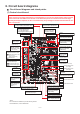
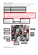
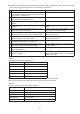
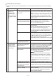
Function Name
Terminal or
connector on
the circuit board
Signal
specifications
Materials Used
Total
extension
External control input
(volt-free contact) (Note 4)
TM2 [Y] [Z]
Level/pulse
(Note 1)
Twisted lead AWG 20 (0.5 mm
2
)
to AWG 15 (1.5 mm
2
)
547 yd.
(500 m)
External control input
(12 V DC, 24 V DC) (Note 4)
TM2 [1] [2]
Level/pulse
(Note 1)
Twisted lead AWG 20 (0.5 mm
2
)
to AWG 15 (1.5 mm
2
)
(Note 2)
Mr. Slim indoor unit control signal TM2 [1] [2] Serial signal
Slim-Lossnay connection cable
(Accessory parts)
AWG 20 (0.5 mm
2
) to AWG 15
(1.5 mm
2
) sheathed PVC cable
55 yd.
(50 m)
Remote/local switching (Note 4) CN32 [1] [3]
Level
(Volt-free contact)
Remote ON/OFF adaptor
(PAC-SE55RA-E or PAC-715AD)
11 yd.
(10 m)
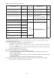
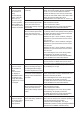
Remote ON/OFF input (Note 4) CN32 [1] [2]
Fan speed 4 input (volt-free contact)
(Note 3)
CN17 [1] [2]
Level
(Volt-free contact)
Remote display adaptor
(PAC-SA88HA-E or PAC-725AD)
Fan speed 3 input (volt-free contact)
(Note 3)
CN17 [1] [3]
Fan speed 2 input (volt-free contact)
(Note 3)
CN17 [1] [4]
Fan speed 1 input (volt-free contact)
(Note 3)
CN17 [1] [5]
Bypass mode input (volt-free contact)
(Note 3)
CN26 [1] [2]
Fan speed switching input
(0 to 10 V DC) (Note 3)
CN26 [4] [5] Analog
Table 2-3 External input/output specifications
<Caution>
• In the group with the multiple Lossnay units, input the signals to the main Lossnay (with address number 1 or
the smallest number other than 0).
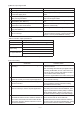
(Note 1) The input signal must conform to the following specifications:
Level signal Volt-free contact, 12 V DC, 24 V DC
Pulse signal Volt-free contact, 12 V DC, 24 V DC, the duration of ON and OFF should be 200 msec.
or more
In the case of relay contact input, use a relay having a contact rating of 15 V DC/0.1 A or higher and a
minimum applicable load of 1 mA or less.
(Note 2) Check the specifications of the external device.
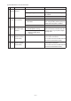
(Note 3) In the group with the multiple Lossnay units, make sure that:
• Connect the signal cables only to the main Lossnay unit when controlling the all Lossnay units
together using PZ-62DR-EA.
• Connect the signal cables to each Lossnay unit when controlling the Lossnay units individually with-
out using PZ-62DR-EA.
• The optional CO
2 sensor (PZ-70CSW-E, PZ-70CSB-E) cannot be used together.
(Note 4) In the group with the multiple Lossnay units, input the signal only to the main Lossnay unit (with
address number 1 or the smallest number other than 0).