
MXZ-3C24NA3 Service Manual


OPERATING PROCEDURE PHOTOS/FIGURES
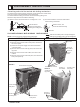
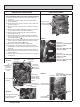
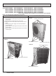
1. Removing the cabinet and the panels
(1) Remove all the screws of the service panel, and remove
the service panel.
(2) Disconnect the power supply cord and indoor/outdoor
connecting wires.
(3) Remove all the screws of the top panel, and remove the
top panel.
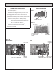
(4) Remove all the screws of the cabinet, and remove the
cabinet.
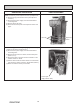
(5) Remove all the screws of the back panel, and remove the
back panel (Photo 3).
141
DISASSEMBLY INSTRUCTIONS13
13-1. MXZ-2C20NA2 MXZ-2C20NA3 MXZ-2C20NA4
NOTE: Turn OFF the power supply before disassembly.
Photo 2
Photo 1
Screws of the cabinet
Screws of the
top panel
Screws of
the cabinet
Screws of
service
panel
Screws of the
top panel
Screws of
the cabinet
Screws of
the cabinet
Screws of the
sub panel
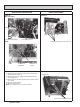
Photo 3
Screw of the rear guard
Screws of the
back panel
Screws of the
back panel
Screws of
the back panel
: Indicates the visible parts in the photos/figures.
: Indicates the invisible parts in the photos/figures.
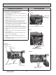
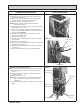
<Detaching method of the terminal with locking mechanism>
The terminal which has the locking mechanism can be detached as shown below.
There are 2 types of the terminal with locking mechanism.
The terminal without locking mechanism can be detached by pulling it out.
Check the shape of the terminal before detaching.
(1) Slide the sleeve and check if there is a locking lever or not. (2) The terminal with this connector shown below
has the locking mechanism.
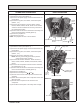
Slide the sleeve.
Pull the terminal while
pushing the locking lever.
Hold the sleeve, and
pull out the terminal slowly.
Connector
Sleeve
Locking lever
OBH702M