Revision M: • MXZ-2C20/3C24/3C30/4C36/5C42NA4 and MXZ-2C20/3C24/3C30NAHZ4 - U1 have been added. OBH702 REVISED EDITION-L is void. U1 OUTDOOR UNIT HFC utilized SERVICE MANUAL No.
Use the specified refrigerant only Never use any refrigerant other than that specified. Doing so may cause a burst, an explosion, or fire when the unit is being used, serviced, or disposed of. Correct refrigerant is specified in the manuals and on the spec labels provided with our products. We will not be held responsible for mechanical failure, system malfunction, unit breakdown or accidents caused by failure to follow the instructions. Prepare the proper tools.
Revision A: • MXZ-3C24NA, MXZ-3C30NA and MXZ-4C36NA have been added. Revision B: • MXZ-3C24/3C30/4C36/5C42NA2 and MXZ-2C20/3C24/3C30NAHZ2 - U1 have been added. Revision C: • 4. SPECIFICATION has been changed. • Some descriptions have been modified. Revision D: • Connectable indoor unit lineups have been modified. • WIRING DIAGRAM (7.) and TEST POINT DIAGRAM AND VOLTAGE (12-7.) have been changed. Revision E: • Capacity and input curve have been corrected.
INDOOR / OUTDOOR UNIT COMPATIBILITY TABLE Connectable indoor unit lineups (Heat pump inverter type) Connectable indoor unit lineups (Heat pump inverter type) Model type Model name Wall mounted Floor standing 4-way cassette Ceiling concealed Ceiling suspended Multi-position MSZ-FE**NA MSZ-FH**NA MSZ-FH**NA2 MSZ-FS**NA MSZ-GE**NA MSZ-GL**NA-U1 MSZ-EF**NA-U1 MFZ-KA**NA MFZ-KJ**NA-U1 SLZ-KA**NA.TH SLZ-KF**NA.TH PLA-A**BA6 PLA-A**EA7 SEZ-KD**NA4.
Connectable indoor unit lineups (Heat pump inverter type) Model type Wall mounted Floor standing 4-way cassette Ceiling concealed Ceiling suspended Multi-position Model name MSZ-FE**NA MSZ-FH**NA MSZ-FH**NA2 MSZ-FS**NA MSZ-GE**NA MSZ-GL**NA-U1 MSZ-EF**NA-U1 MFZ-KA**NA MFZ-KJ**NA-U1 SLZ-KA**NA.TH SLZ-KF**NA.TH PLA-A**BA6 PLA-A**EA7 SEZ-KD**NA4.TH PEAD-A**AA5 PCA-A**KA6.
Connectable indoor unit lineups (Heat pump inverter type) Model type Model name Wall mounted Floor standing 4-way cassette Ceiling concealed Ceiling suspended Multi-position MSZ-FE**NA MSZ-FH**NA MSZ-FH**NA2 MSZ-FS**NA MSZ-GE**NA MSZ-GL**NA-U1 MSZ-EF**NA-U1 MFZ-KA**NA MFZ-KJ**NA-U1 SLZ-KA**NA.TH SLZ-KF**NA.TH PLA-A**BA6 PLA-A**EA7 SEZ-KD**NA4.TH PEAD-A**AA5 PCA-A**KA6.
Connectable indoor unit lineups (Heat pump inverter type) Model type Wall mounted Floor standing 4-way cassette Ceiling concealed Ceiling suspended Multi-position Model name MSZ-FE**NA MSZ-FH**NA MSZ-FH**NA2 MSZ-FS**NA MSZ-GE**NA MSZ-GL**NA-U1 MSZ-EF**NA-U1 MFZ-KA**NA MFZ-KJ**NA-U1 SLZ-KA**NA.TH SLZ-KF**NA.TH PLA-A**BA6 PLA-A**EA7 SEZ-KD**NA4.TH PEAD-A**AA5 PCA-A**KA6.
1 TECHNICAL CHANGES MXZ-5C42NA MXZ-2C20NAHZ MXZ-3C24NAHZ MXZ-3C30NAHZ 1. New model MXZ-3C24NA MXZ-3C30NA MXZ-4C36NA 1. New model MXZ-3C24NA MXZ-3C30NA MXZ-4C36NA MXZ-5C42NA MXZ-3C24NA2 MXZ-3C30NA2 MXZ-4C36NA2 MXZ-5C42NA2 - MXZ-2C20NAHZ MXZ-3C24NAHZ MXZ-3C30NAHZ U1 U1 U1 MXZ-2C20NAHZ2 MXZ-3C24NAHZ2 MXZ-3C30NAHZ2 - U1 U1 U1 U1 1. Outdoor control P.C. board has been changed. MXZ-2C20NA2 - U1 1. New model MXZ-2C20NA2 - U1 MXZ-2C20NA2 - U4 1. Outdoor fan motor has been changed. 2.
2 SAFETY PRECAUTION 2-1. ALWAYS OBSERVE FOR SAFETY Before obtaining access to terminal, all supply circuit must be disconnected. Preparation before the repair service Precautions during the repair service • Prepare the proper tools. • Prepare the proper protectors. • Provide adequate ventilation. • After stopping the operation of the air conditioner, turn off the power-supply breaker. • Discharge the condenser before the work involving the electric parts.
[1] Cautions for service (1) Perform service after recovering the refrigerant left in unit completely. (2) Do not release refrigerant in the air. (3) After completing service, charge the cycle with specified amount of refrigerant. (4) If moisture or foreign matter might have entered the refrigerant piping during service, ensure to remove them. [2] Additional refrigerant charge When charging directly from cylinder (1) Check that cylinder for R410A on the market is a siphon type.
2-3. Cautions for refrigerant piping work Refrigerant R410A is adopted for replacement inverter series. Although the refrigerant piping work for R410A is the same as for R22, exclusive tools are necessary so as not to mix with different kind of refrigerant. Furthermore as the working pressure of R410A is 1.6 times higher than that of R22, their sizes of flared sections and flare nuts are different.
Tools for R410A (The following table shows whether conventional tools can be used or not.
3 PART NAMES AND FUNCTIONS MXZ-2C20NA2 MXZ-2C20NA3 MXZ-2C20NA4 Air inlet (Back and side) Air outlet Drain outlet MXZ-3C24NA MXZ-3C30NA MXZ-4C36NA MXZ-3C24NA2 MXZ-3C30NA2 MXZ-4C36NA2 MXZ-3C24NA3 MXZ-3C30NA3 MXZ-4C36NA3 MXZ-3C24NA4 MXZ-3C30NA4 MXZ-4C36NA4 Air inlet (Back and side) Air outlet Drain outlet MXZ-5C42NA MXZ-2C20NAHZ MXZ-3C24NAHZ MXZ-3C30NAHZ MXZ-5C42NA2 MXZ-2C20NAHZ2 MXZ-3C24NAHZ2 MXZ-3C30NAHZ2 MXZ-5C42NA3 MXZ-2C20NAHZ3 MXZ-3C24NAHZ3 MXZ-3C30NAHZ3 Air inlet (Back and side) Air o
4 SPECIFICATION Item Capacity Power consumption Cooling Heating 47 Heating 17 Cooling Heating 47 Heating 17 Cooling Cooling Heating Heating *1 *1 *2 *1 *1 *2 Outdoor model Indoor type Btu/h Btu/h Btu/h W W W EER SEER HSPF IV(V) COP External finish Power supply V, phase, Hz Max. fuse size (time delay) A Min. circuit ampacity A Fan motor F.L.A Model Winding resistance Ω (at 68 ºF) Compressor R.L.A L.R.A Refrigerant control Sound level dB(A) Defrost method W in. Dimensions D in. H in. Weight lb.
Item Capacity Power consumption Cooling Heating 47 Heating 17 Cooling Heating 47 Heating 17 Cooling Cooling Heating Heating *1 *1 *2 *1 *1 *2 Outdoor model Indoor type Btu/h Btu/h Btu/h W W W EER2 SEER2 HSPF2 COP2 External finish Power supply V, phase, Hz Max. fuse size (time delay) A Min. circuit ampacity A Fan motor F.L.A Model Winding resistance Ω (at 68 ºF) Compressor R.L.A L.R.A Refrigerant control Sound level dB(A) Defrost method W in. Dimensions D in. H in. Weight lb.
Item Capacity Power consumption Cooling Heating 47 Heating 17 Cooling Heating 47 Heating 17 Cooling Cooling Heating Heating *1 *1 *2 *1 *1 *2 Outdoor model Indoor type Btu/h Btu/h Btu/h W W W EER SEER HSPF IV(V) COP External finish Power supply V, phase, Hz Max. fuse size (time delay) A Min. circuit ampacity A Fan motor F.L.A Model Winding resistance Ω (at 68 ºF) Compressor R.L.A L.R.A Refrigerant control Sound level dB(A) Defrost method W in. Dimensions D in. H in. Weight lb.
Item Capacity Power consumption Cooling Heating 47 Heating 17 Cooling Heating 47 Heating 17 Cooling Cooling Heating Heating *1 *1 *2 *1 *1 *2 Outdoor model Indoor type Btu/h Btu/h Btu/h W W W EER2 SEER2 HSPF2 COP2 External finish Power supply V, phase, Hz Max. fuse size (time delay) A Min. circuit ampacity A Fan motor F.L.A Model Winding resistance Ω (at 68 ºF) Compressor R.L.A L.R.A Refrigerant control Sound level dB(A) Defrost method W in. Dimensions D in. H in. Weight lb.
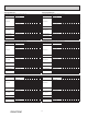
5 NOISE CRITERIA CURVES MXZ-2C20NA2 MXZ-2C20NA3 MXZ-2C20NA4 FAN SPEED FUNCTION SPL(dB(A)) High Cooling 50 High Heating 54 LINE MXZ-3C24NA MXZ-3C24NA2 MXZ-3C24NA3 80 70 NC-70 60 NC-60 50 NC-50 40 NC-40 30 NC-30 20 High Heating 55 LINE 70 NC-70 60 NC-60 50 NC-50 40 NC-40 30 NC-30 NC-20 APPROXIMATE THRESHOLD OF HEARING FOR CONTINUOUS NOISE NC-20 125 250 500 1000 2000 4000 8000 63 125 BAND CENTER FREQUENCIES, Hz MXZ-3C24NA4 250 500 1000 2000 4000 8000 BAND CENTER F
MXZ-3C30NA4 FAN SPEED FUNCTION SPL(dB(A)) High Cooling 52 High Heating 56 LINE MXZ-4C36NA MXZ-4C36NA2 MXZ-4C36NA3 80 70 NC-70 60 NC-60 50 NC-50 40 NC-40 30 NC-30 20 10 APPROXIMATE THRESHOLD OF HEARING FOR CONTINUOUS NOISE High Heating 56 LINE 63 NC-70 60 NC-60 50 NC-50 40 NC-40 30 NC-30 20 125 250 500 1000 2000 4000 APPROXIMATE THRESHOLD OF HEARING FOR CONTINUOUS NOISE NC-20 10 8000 63 125 250 500 1000 2000 4000 8000 BAND CENTER FREQUENCIES, Hz FAN SPEED FUNC
MXZ-2C20NAHZ MXZ-2C20NAHZ2 MXZ-2C20NAHZ3 MXZ-2C20NAHZ4 FAN SPEED FUNCTION SPL(dB(A)) High Cooling 54 High Heating 58 LINE MXZ-3C24NAHZ MXZ-3C24NAHZ2 MXZ-3C24NAHZ3 MXZ-3C24NAHZ4 70 NC-70 60 NC-60 50 NC-50 40 NC-40 30 NC-30 OCTAVE BAND SOUND PRESSURE LEVEL, 0dB = 0.0002 MICRO BAR OCTAVE BAND SOUND PRESSURE LEVEL, 0dB = 0.
6 OUTLINES AND DIMENSIONS Unit: inch (mm) MXZ-2C20NA2 MXZ-2C20NA3 MXZ-2C20NA4 6-23/32” 23/32” Air Inlet 15/32” 11/16” Air Inlet Air Outlet 3-ø(1-5/16”) Drain hole (Bolt Pitch) 11/16” 12-3/8” 15-19/32” 19-11/16” 14-3/16” 8-5/32” 21/32” 1-11/32” 6-21/32” 2-9/16” 4-(13/32”×13/16”) Oval Hole (Foundation Bolt M8) Handle 13/32” 33-1/16” 1-3/16” 7-7/8” 9-7/16” Connecting wire hole 13” 1/2” 2-19/32” 27-15/16” 14-3/16” 18-1/8 5-5/16” 1-25/32” 3-5/16” 1-1/32” Connecting wire hole LIQ G
Unit: inch (mm) MXZ-3C24NA MXZ-3C24NA2 MXZ-3C24NA3 MXZ-3C24NA4 MXZ-3C30NA MXZ-3C30NA2 MXZ-3C30NA3 MXZ-3C30NA4 (NA, NA2, NA3) Conduit plates Conduit connector Lock nut (NA4) Conduit plate Conduit connector Lock nut OBH702M 34 Conduit plate
Unit: inch (mm) MXZ-4C36NA MXZ-4C36NA2 MXZ-4C36NA3 MXZ-4C36NA4 (NA, NA2, NA3) Conduit plates Conduit connector Lock nut (NA4) Conduit plate Conduit connector Lock nut OBH702M 35 Conduit plate
Unit: inch (mm) MXZ-5C42NA MXZ-5C42NA2 MXZ-5C42NA3 MXZ-5C42NA4 Conduit plate Top Lock nut OBH702M 36 Conduit connector Conduit plate Under
MXZ-2C20NAHZ MXZ-2C20NAHZ2 MXZ-2C20NAHZ3 MXZ-2C20NAHZ4 Lock nut Unit: inch (mm) Conduit plate Conduit connector OBH702M 37
MXZ-3C24NAHZ MXZ-3C24NAHZ2 MXZ-3C24NAHZ3 MXZ-3C24NAHZ4 MXZ-3C30NAHZ MXZ-3C30NAHZ2 MXZ-3C30NAHZ3 MXZ-3C30NAHZ4 Lock nut Unit: inch (mm) Conduit plate Top Conduit connector Conduit plate Under OBH702M 38
7 WIRING DIAGRAM MXZ-2C20NA2 L WH RD WH RD TAB5 TAB6 IC501 MC U MS 3~ W BK WH VRD BK U WH V RD W TAB4 X52C TAB3 TAB1 BU IC411 IC402 IC401 TAB2 PTC1 CNMC 1 BK 3 BU CIRCUIT TB1 BREAKER L1 L2 GR POWER SUPPLY 208/230V AC 60Hz CNAC1 CB3 + CB2 + CB1 + CN171 1 2 RT64 D1 X65 GNYN F1 F2 PTC2 OUTDOOR POWER P.C.
MXZ-2C20NA3 [If the reactor does not have a number display, refer to the figure below.] No.4 No.1 OBH702M No.3 No.
MXZ-2C20NA4 [If the reactor does not have a number display, refer to the figure below.] No.4 No.1 OBH702M No.3 No.
MXZ-3C24NA MXZ-3C30NA [Connection between reactor and outdoor power P.C. board] * There are 2 types of reactors, which may have a number display. Even if there is a number display, please wire as shown in the figure below.
MXZ-3C24NA2 MXZ-3C30NA2 [Connection between reactor and outdoor power P.C. board] * There are 2 types of reactors, which may have a number display. Even if there is a number display, please wire as shown in the figure below.
MXZ-3C24NA3 MXZ-3C30NA3 [If the reactor does not have a number display, refer to the figure below.] No.4 No.1 OBH702M No.3 No.
MXZ-3C24NA4 MXZ-3C30NA4 [If the reactor does not have a number display, refer to the figure below.] No.4 No.1 OBH702M No.3 No.
MXZ-4C36NA [Connection between reactor and outdoor power P.C. board] * There are 2 types of reactors, which may have a number display. Even if there is a number display, please wire as shown in the figure below.
MXZ-4C36NA2 [Connection between reactor and outdoor power P.C. board] * There are 2 types of reactors, which may have a number display. Even if there is a number display, please wire as shown in the figure below.
MXZ-4C36NA3 [If the reactor does not have a number display, refer to the figure below.] No.4 No.1 OBH702M No.3 No.
MXZ-4C36NA4 [If the reactor does not have a number display, refer to the figure below.] No.4 No.1 OBH702M No.3 No.
MXZ-5C42NA L1 L2 WHT WHT RED TAB5 RED TAB3 TAB6 IC411 IC501 X52CA TAB4 IC401 V U MS W 3~ 7 CNF1 1 CNDC 1 3 7 CN702 3 BLU CN152 1 2 TBE1 TBE2 TBE3 TBE4 CNAC2 3 1 CN171 2 1 CN741 5 1 LED1 CNTH1 1 8 5 CNTH2 1 2 1 5 t° t° RT61 RT62 SYMBOL CB1~4 D1 F1, F2 F711 HPS IC401 IC411 IC501 IC801 PTC1~3 RT61 RT62 RT64 RT65 RT68 t° RT68 t° RT65 NAME SYMBOL SMOOTHING CAPACITOR L1, L2 DIODE LED 1~3 FUSE (T6.3AL 250V) LEV A~E FUSE (T3.
MXZ-5C42NA2 OBH702M 51
MXZ-5C42NA3 L2 WH RD TAB5 RD TAB3 TAB6 TAB4 IC411 IC501 X52CA IC401 X52CB X65A V U MS W 3~ 7 CNF1 MC 1 CNDC TBE1 TBE2 7 CN702 LED3 LED2 1 CN741 CNTH1 1 5 1 8 t° RT68 (BK) CN795 5 CNTH2 1 2 t° RT65 NAME SMOOTHING CAPACITOR DIODE FUSE (T6.3AL 250V) FUSE (T3.
MXZ-5C42NA4 L2 WH RD TAB5 RD TAB3 TAB6 TAB4 IC411 IC501 X52CA IC401 X52CB X65A V U MS W 3~ 7 CNF1 MC 1 CNDC TBE1 TBE2 7 CN702 LED3 1 CN741 5 1 LED1 CNTH1 1 8 t° RT68 (BK) CN795 5 CNTH2 1 2 t° RT65 NAME SMOOTHING CAPACITOR DIODE FUSE (T6.3AL 250V) FUSE (T3.
MXZ-2C20NAHZ OBH702M 54
MXZ-2C20NAHZ2 OBH702M 55
MXZ-2C20NAHZ3 L2 WH RD TAB5 RD TAB3 TAB6 TAB4 IC411 IC501 X52CA IC401 D1 CB2 1 1 7 CN152 1 2 TBE1 TBE2 V U MS W 3~ 1 7 CNF1 MC 1 CNDC 3 1 7 CN702 T801 LED3 LED2 CNAC2 3 1 CN171 1 2 t° 1 CNAC 1 2 CN701 OUTDOOR CONTROL P.C. BOARD 3 WH BU F711 IC801 1 CN741 CNTH1 1 SYMBOL CB1~4 D1 F1, F2 F711 HPS H IC401 IC411 IC501 IC801 L1, L2 LED 1~3 LEV A, B MC MF PTC1~3 TBE3 TBE4 RT64 5 1 8 t° RT68 CNTH2 1 2 1 NAME SMOOTHING CAPACITOR DIODE FUSE (T6.3AL 250V) FUSE (T3.
MXZ-2C20NAHZ4 L2 WH RD TAB5 RD TAB3 TAB6 TAB4 IC411 IC501 X52CA IC401 D1 CB2 1 CNMC 3 1 7 CN152 1 2 TBE1 TBE2 V U MS W 3~ 1 7 CNF1 MC 1 CNDC 3 1 7 CN702 T801 LED3 LED2 CN171 1 2 t° 1 CNAC 1 2 CN701 OUTDOOR CONTROL P.C. BOARD 3 WH BU F711 IC801 1 CN741 CNTH1 1 SYMBOL CB1~4 D1 F1, F2 F711 HPS H IC401 IC411 IC501 IC801 L1, L2 LED 1~3 LEV A, B MC MF PTC1~3 CNAC2 3 1 RT64 5 1 8 t° RT68 CNTH2 1 2 NAME SMOOTHING CAPACITOR DIODE FUSE (T6.3AL 250V) FUSE (T3.
MXZ-3C24NAHZ MXZ-3C30NAHZ OBH702M 58
MXZ-3C24NAHZ2 MXZ-3C30NAHZ2 OBH702M 59
MXZ-3C24NAHZ3 MXZ-3C30NAHZ3 L2 WH RD TAB5 RD TAB6 TAB3 TAB4 IC411 IC501 X52CA IC401 1 CNMC 3 1 7 CN152 1 2 TBE1 TBE2 V U MS W 3~ 1 7 CNF1 MC 1 CNDC 3 1 7 CN702 T801 LED3 LED2 1 CNTH1 SYMBOL CB1~4 D1 F1, F2 F711 HPS H IC401 IC411 IC501 IC801 L1, L2 LED 1~3 LEV A~C MC MF PTC1~3 CNAC2 3 1 CN171 1 2 t° CN741 8 t° BK 1 CNAC 1 2 CN701 OUTDOOR CONTROL P.C. BOARD 3 WH BU F711 3 5 1 (BU) CN793 5 CNTH2 1 2 RT68 NAME SMOOTHING CAPACITOR DIODE FUSE (T6.3AL 250V) FUSE (T3.
MXZ-3C24NAHZ4 MXZ-3C30NAHZ4 L2 WH RD TAB5 RD TAB6 TAB3 TAB4 IC411 IC501 X52CA IC401 D1 1 CNMC 3 1 7 CN152 1 2 TBE1 TBE2 V U MS W 3~ 1 7 CNF1 MC 1 CNDC 3 1 7 CN702 T801 LED3 LED2 1 CNTH1 SYMBOL CB1~4 D1 F1, F2 F711 HPS H IC401 IC411 IC501 IC801 L1, L2 LED 1~3 LEV A~C MC MF PTC1~3 CN171 1 2 t° CN741 8 t° BK 1 CNAC 1 2 CN701 OUTDOOR CONTROL P.C. BOARD 3 WH BU F711 3 5 1 (BU) CN793 5 CNTH2 1 2 RT68 NAME SMOOTHING CAPACITOR DIODE FUSE (T6.3AL 250V) FUSE (T3.
8 REFRIGERANT SYSTEM DIAGRAM Unit: inch (mm) MXZ-2C20NA2 MXZ-2C20NA3 MXZ-2C20NA4 Service port R.V. coil OFF ON Refrigerant flow in cooling Refrigerant flow in heating Compressor Discharge temperature thermistor RT62 Muffler Service port High pressure switch Union Indoor unit B ø 3/8 Indoor unit A ø 3/8 Stop valve with service port 4-way valve Sub Muffler Outdoor heat exchanger temperature thermistor RT68 HEX-OUT FAN-OUT Indoor unit A Capillary tube O.D.0.16 x I.D.0.11 x 3.94 (ø4.0 x ø2.
MXZ-2C20NA2 MXZ-2C20NA3 MXZ-2C20NA4 Operating Range Indoor intake air temperature Outdoor intake air temperature Cooling Heating Maximum 95°FDB, 71°FWB 115°FDB Minimum 67°FDB, 57°FWB 14°FDB Maximum 80°FDB, 67°FWB 75°FDB, 65°FWB Minimum 70°FDB, 60°FWB 6°FDB, 5°FWB MAX. REFRIGERANT PIPING LENGTH & PIPE SIZE SELECTION Piping length each indoor unit (a, b) Total piping length (a+b) Bending point for each unit Total bending point 82 ft. MAX. 164 ft. MAX. 25 MAX. 50 MAX.
Unit: inch (mm) MXZ-3C24NA MXZ-3C24NA2 MXZ-3C24NA3 MXZ-3C30NA MXZ-3C30NA2 MXZ-3C30NA3 R.V.coil OFF ON Refrigerant flow in heating Refrigerant flow in cooling Accumulator Compressor Service port High pressure switch Muffler Service port Union Header(Gas) Stop valve (with service port) ø 1/2 Indoor unit A Compressor shell temperature thermistor RT62 4-way valve ø 3/8 Indoor unit B Sub muffler ø 3/8 Indoor unit C Header (Evaporator) Outdoor heat exchanger ø 3/8 Indoor unit D Capillary tube O.
MXZ-3C24NA MXZ-3C24NA2 MXZ-3C24NA3 MXZ-3C24NA4 MXZ-3C30NA MXZ-3C30NA2 MXZ-3C30NA3 MXZ-3C30NA4 Operating Range Indoor intake air temperature Outdoor intake air temperature Cooling Heating Maximum 95°FDB, 71°FWB 115°FDB Minimum 67°FDB, 57°FWB 14°FDB Maximum 80°FDB, 67°FWB 75°FDB, 65°FWB Minimum 70°FDB, 60°FWB 6°FDB, 5°FWB MAX. REFRIGERANT PIPING LENGTH & PIPE SIZE SELECTION Piping length each indoor unit (a, b, c) Total piping length (a+b+c) Bending point for each unit Total bending point 82 ft.
Unit: inch (mm) MXZ-4C36NA MXZ-4C36NA2 MXZ-4C36NA3 R.V.
MXZ-4C36NA MXZ-4C36NA2 MXZ-4C36NA3 MXZ-4C36NA4 Operating Range Indoor intake air temperature Outdoor intake air temperature Cooling Heating Maximum 95°FDB, 71°FWB 115°FDB Minimum 67°FDB, 57°FWB 14°FDB Maximum 80°FDB, 67°FWB 75°FDB, 65°FWB Minimum 70°FDB, 60°FWB 6°FDB, 5°FWB MAX. REFRIGERANT PIPING LENGTH & PIPE SIZE SELECTION Piping length each indoor unit (a, b, c, d) Total piping length (a+b+c+d) Bending point for each unit Total bending point 82 ft. MAX. 230 ft. MAX. 25 MAX. 70 MAX.
Unit: inch (mm) MXZ-5C42NA R.V.coil OFF ON Refrigerant flow in heating Refrigerant flow in cooling Accumulator Compressor Oil separator Union Indoor unit A Indoor unit B Indoor unit C Indoor unit D Indoor unit E High pressure switch Service port ø 1/2 4-way valve ø 3/8 Stop valve (with service port) ø 3/8 ø 3/8 Indoor unit D Indoor unit E Header(Evaporator) 2-way solenoid valve ø 3/8 ø 1/4 Strainer #100 Outdoor heat exchanger Capillary tube O.D.0.10 x I.D.0.02 x 39.37 (ø2.5 x ø0.
MXZ-5C42NA MXZ-5C42NA2 MXZ-5C42NA3 MXZ-5C42NA4 Operating Range Indoor intake air temperature Outdoor intake air temperature Cooling Heating Maximum 95°FDB, 71°FWB 115°FDB Minimum 67°FDB, 57°FWB 14°FDB Maximum 80°FDB, 67°FWB 75°FDB, 65°FWB Minimum 70°FDB, 60°FWB 6°FDB, 5°FWB MAX. REFRIGERANT PIPING LENGTH & PIPE SIZE SELECTION Piping length each indoor unit (a, b, c, d, e) Total piping length (a+b+c+d+e) Bending point for each unit Total bending point 82 ft. MAX. 262 ft. MAX. 25 MAX. 80 MAX.
Unit: inch (mm) MXZ-2C20NAHZ R.V.coil OFF ON Refrigerant flow in heating Refrigerant flow in cooling Accumulator Compressor Oil separator Compressor shell temperature thermistor RT62 Service port High pressure switch Union Header(Gas) Service port ø 3/8 4-way valve Indoor unit A Stop valve (with service port) Header(Evaporator) 2-way solenoid valve ø 3/8 Outdoor heat exchanger Capillary tube O.D.0.10 x I.D.0.02 x 39.37 (ø2.5 x ø0.
MXZ-2C20NAHZ MXZ-2C20NAHZ2 MXZ-2C20NAHZ3 MXZ-2C20NAHZ4 Operating Range Indoor intake air temperature Outdoor intake air temperature Cooling Heating Maximum 95°FDB, 71°FWB 115°FDB Minimum 67°FDB, 57°FWB 14°FDB Maximum 80°FDB, 67°FWB 75°FDB, 65°FWB Minimum 70°FDB, 60°FWB -12°FDB, -13°FWB MAX. REFRIGERANT PIPING LENGTH & PIPE SIZE SELECTION Piping length each indoor unit (a, b) Total piping length (a+b) Bending point for each unit Total bending point 82 ft. MAX. 164 ft. MAX. 25 MAX. 50 MAX.
Unit: inch (mm) MXZ-3C24NAHZ MXZ-3C30NAHZ R. V. coil OFF ON Refrigerant flow in heating Refrigerant flow in cooling Accumulator Compressor Service port Compressor shell temperature thermistor RT62 Oil separator High pressure switch Union Indoor unit A Indoor unit B Indoor unit C Indoor unit A Header(Gas) Service port ø 1/2 4-way valve Stop valve (with service port) ø 3/8 2-way solenoid valve ø 3/8 Outdoor heat exchanger Capillary tube O.D.0.10 x I.D.0.02 x 39.37 (ø2.5 x ø0.
MXZ-3C24NAHZ MXZ-3C24NAHZ2 MXZ-3C24NAHZ3 MXZ-3C24NAHZ4 MXZ-3C30NAHZ MXZ-3C30NAHZ2 MXZ-3C30NAHZ3 MXZ-3C30NAHZ4 Operating Range Indoor intake air temperature Outdoor intake air temperature Cooling Heating Maximum 95°FDB, 71°FWB 115°FDB Minimum 67°FDB, 57°FWB 14°FDB Maximum 80°FDB, 67°FWB 75°FDB, 65°FWB Minimum 70°FDB, 60°FWB -12°FDB, -13°FWB MAX.
PUMPING DOWN When relocating or disposing of the air conditioner, pump down the system following the procedure below so that no refrigerant is released into the atmosphere. 1) Turn off the breaker. 2) Connect the gauge manifold valve to the service port of the stop valve on the gas pipe side of the outdoor unit. 3) Fully close the stop valve on the liquid pipe side of the outdoor unit. 4) Turn on the breaker. 5) Start the emergency COOL operation on all the indoor units. 6) When the pressure gauge shows 0.
9 DATA Model Indoor type Item Total Capacity SHF Input Electrical Power supply (V, phase, Hz) circuit Input Comp. current (208/230V) Fan motor current Refrigerant Condensing pressure circuit Suction pressure Discharge temperature Condensing temperature Suction temperature Comp. shell bottom temp. Ref.
Model Indoor type Item Total Capacity SHF Input Electrical Power supply (V, phase, Hz) circuit Input Comp. current (208/230V) Fan motor current Refrigerant Condensing pressure circuit Suction pressure Discharge temperature Condensing temperature Suction temperature Comp. shell bottom temp. Ref.
Model Indoor type Item Total Capacity SHF Input Electrical Power supply (V, phase, Hz) circuit Input Comp. current (208/230V) Fan motor current Refrigerant Condensing pressure circuit Suction pressure Discharge temperature Condensing temperature Suction temperature Comp. shell bottom temp. Ref.
Model Indoor type Item Total Capacity SHF Input Electrical Power supply (V, phase, Hz) circuit Input Comp. current (208/230V) Fan motor current Refrigerant Condensing pressure circuit Suction pressure Discharge temperature Condensing temperature Suction temperature Comp. shell bottom temp. Ref.
Model Indoor type Item Total Capacity SHF Input Electrical Power supply (V, phase, Hz) circuit Input Comp. current (208/230V) Fan motor current Refrigerant Condensing pressure circuit Suction pressure Discharge temperature Condensing temperature Suction temperature Comp. shell bottom temp. Ref.
Model Indoor type Item Total Capacity SHF Input Electrical Power supply (V, phase, Hz) circuit Input Comp. current (208/230V) Fan motor current Refrigerant Condensing pressure circuit Suction pressure Discharge temperature Condensing temperature Suction temperature Comp. shell bottom temp. Ref.
9-1. OPERATING RANGE (1) POWER SUPPLY Model MXZ-2C20NA2 MXZ-2C20NA3 MXZ-2C20NA4 MXZ-3C24NA MXZ-3C24NA2 MXZ-3C24NA3 MXZ-3C24NA4 MXZ-3C30NA MXZ-3C30NA2 Outdoor unit MXZ-3C30NA3 MXZ-3C30NA4 MXZ-4C36NA MXZ-4C36NA2 MXZ-4C36NA3 MXZ-4C36NA4 MXZ-5C42NA MXZ-5C42NA2 MXZ-5C42NA3 MXZ-5C42NA4 MXZ-2C20NAHZ MXZ-2C20NAHZ2 MXZ-2C20NAHZ3 MXZ-2C20NAHZ4 MXZ-3C24NAHZ MXZ-3C24NAHZ2 MXZ-3C24NAHZ3 MXZ-3C24NAHZ4 MXZ-3C30NAHZ MXZ-3C30NAHZ2 MXZ-3C30NAHZ3 MXZ-3C30NAHZ4 Rating Guaranteed Voltage Min. 198 V 208 V 230 V Max.
MXZ-3C24NA MXZ-2C20NA2 MXZ-2C20NA3 MXZ-2C20NA4 MXZ-2C20NAHZ MXZ-2C20NAHZ2 MXZ-2C20NAHZ3 MXZ-2C20NAHZ4 MXZ-3C30NA MXZ-3C24NA2 MXZ-3C24NA3 MXZ-3C24NA4 MXZ-3C24NAHZ MXZ-3C24NAHZ2 MXZ-3C24NAHZ3 MXZ-3C24NAHZ4 MXZ-4C36NA MXZ-3C30NA2 MXZ-3C30NA3 MXZ-3C30NA4 MXZ-3C30NAHZ MXZ-3C30NAHZ2 MXZ-3C30NAHZ3 MXZ-3C30NAHZ4 MXZ-5C42NA MXZ-4C36NA2 MXZ-4C36NA3 MXZ-4C36NA4 MXZ-5C42NA2 MXZ-5C42NA3 MXZ-5C42NA4 The standard specifications apply only to the operation of the air conditioner under normal conditions.
8.8 10.7 10.5 5.7 8.0 9.7 9.5 5.1 7.2 8.7 8.5 4.6 6.5 7.8 7.6 4.1 5.8 6.9 6.7 3.6 5.1 6.0 5.8 Capacity correction factors 6.2 Cooling capacity 1.3 1.2 1.1 1.0 79 75 72 68 67 64 60 0.9 0.8 0.7 Indoor intake air Wet-bulb temperature (°F) 14 15 class 11.4 12 class 9.6 11.7 09 class 6.8 06 class Indoor air Wet-bulb temperature difference (°F) 9-2.
10.5 13.2 12.1 5.7 8.0 9.7 9.5 12.0 10.9 5.1 7.2 8.7 8.5 10.7 9.8 4.6 6.5 7.8 7.6 9.5 8.7 4.1 5.8 6.9 6.7 8.3 7.6 3.6 5.1 6.0 5.8 7.1 6.5 MXZ-3C24NA4 MXZ-3C30NA4 MXZ-4C36NA4 Cooling capacity 1.3 1.2 1.1 1.0 0.9 0.8 0.7 Indoor intake air Wet-bulb temperature (°F) 14 24 class 8.8 10.7 18 class 6.2 15 class 13.2 12 class 11.4 14.5 09 class 9.6 11.7 MXZ-3C24NA3 MXZ-3C30NA3 MXZ-4C36NA3 Capacity correction factors MXZ-3C24NA2 MXZ-3C30NA2 MXZ-4C36NA2 6.
10.5 13.2 12.1 8.0 9.7 9.5 12.0 10.9 5.1 7.2 8.7 8.5 10.7 9.8 4.6 6.5 7.8 7.6 9.5 8.7 4.1 5.8 6.9 6.7 8.3 7.6 3.6 5.1 6.0 5.8 7.1 6.5 MXZ-5C42NA4 Cooling capacity 1.3 1.2 1.1 1.0 0.8 0.7 Indoor intake air Wet-bulb temperature (°F) 14 24 34 44 54 64 74 84 94 104 114 Outdoor intake air Dry-bulb temperature (°F) Total input (Cooling) Input correction factors 1.3 1.2 1.1 1.0 Indoor intake air Wet-bulb temperature (°F) 0.7 0.6 0.5 0.4 31.3 41.4 45.4 49.1 36.7 20.
10.5 13.2 12.1 8.0 9.7 9.5 12.0 10.9 5.1 7.2 8.7 8.5 10.7 9.8 4.6 6.5 7.8 7.6 9.5 8.7 4.1 5.8 6.9 6.7 8.3 7.6 3.6 5.1 6.0 5.8 7.1 6.5 Capacity correction factors 8.8 10.7 5.7 Cooling capacity 1.3 1.2 1.1 1.0 0.9 0.8 0.7 Indoor intake air Wet-bulb temperature (°F) 14 24 class 6.2 18 class 13.2 15 class 11.4 14.5 12 class 9.6 11.7 09 class 6.
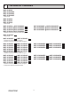
9-3. CAPACITY AND INPUT CORRECTION BY MEANS OF INVERTER OUTPUT FREQUENCY (OUTDOOR UNIT: MXZ-2C20NA2 MXZ-2C20NA3 MXZ-2C20NA4) 1. 06-class unit in single operation Total input Capacity 2.0 2.5 2.0 1.5 1.5 1.0 1.0 0.5 0.5 0 50 100 Frequency 0 150Hz 50 100 Frequency 150 Hz Total input Capacity 2.5 2.0 2.0 1.5 1.5 1.0 1.0 0.5 0.5 0 50 100 Frequency 150 Hz 0 50 100 Frequency 150 Hz 2.
(OUTDOOR UNIT: MXZ-3C24NA MXZ-3C24NA2 MXZ-3C24NA3 MXZ-3C24NA4 MXZ-3C30NA MXZ-3C30NA2 MXZ-3C30NA3 MXZ-3C30NA4 MXZ-4C36NA MXZ-4C36NA2 MXZ-4C36NA3 MXZ-4C36NA4) 1. 06-class unit in single operation Total input Capacity 2.0 2.0 1.5 1.5 1.5 1.0 1.0 1.0 0.5 0.5 0.5 2.0 Total input Capacity 2.5 2.0 1.5 1.0 0 50 100 Frequency 150Hz 0 50 100 Frequency 150 Hz 0 0.5 50 100 Frequency 150 Hz 0 50 100 Frequency 150 Hz 2. 09-class unit in single operation 2.
(OUTDOOR UNIT: MXZ-5C42NA MXZ-2C20NAHZ MXZ-3C24NAHZ MXZ-3C30NAHZ 1. 06-class unit in single operation MXZ-5C42NA2 MXZ-2C20NAHZ2 MXZ-3C24NAHZ2 MXZ-3C30NAHZ2 Total input Capacity MXZ-5C42NA3 MXZ-2C20NAHZ3 MXZ-3C24NAHZ3 MXZ-3C30NAHZ3 Total input Capacity 2.0 2.0 1.5 1.5 1.5 1.5 1.0 1.0 1.0 1.0 0.5 0.5 0.5 0.5 2.0 0 50 100 Frequency 150Hz 0 50 100 Frequency 150 Hz 0 50 100 Frequency MXZ-5C42NA4 MXZ-2C20NAHZ4 MXZ-3C24NAHZ4 MXZ-3C30NAHZ4) 2.
9-4. OUTDOOR LOW PRESSURE AND OUTDOOR UNIT CURRENT 1. 06-class unit in single operation (OUTDOOR UNIT: MXZ-2C20NA2 MXZ-2C20NA3 MXZ-2C20NA4) (1) COOL operation D ata is based on the condition of indoor humidity 50% Air flow speed: High Inverter output frequency: 40 Hz 1. Set emergency switch to COOL or HEAT. The switch is located on indoor unit. 2. Press emergency run ON/OFF button. 3. Compressor starts running at 40 Hz (COOL) or 48 Hz (HEAT). 4.
2. 09-class unit in single operation (OUTDOOR UNIT: MXZ-2C20NA2 MXZ-2C20NA3 MXZ-2C20NA4) (1) COOL operation D ata is based on the condition of indoor humidity 50% Air flow speed: High Inverter output frequency: 40 Hz 1. Set emergency switch to COOL or HEAT. The switch is located on indoor unit. 2. Press emergency run ON/OFF button. 3. Compressor starts running at 40 Hz (COOL) or 48 Hz (HEAT). 4. Indoor fan runs at High speed and continues for 30 minutes. 5.
3. 12-class unit in single operation (OUTDOOR UNIT: MXZ-2C20NA2 MXZ-2C20NA3 MXZ-2C20NA4) (1) COOL operation Data is based on the condition of indoor humidity 50% Air flow speed: High Inverter output frequency: 40 Hz 160 6.0 perat lb tem y-bu or Dr Indo F) ure (˚ 86 5.0 80 150 Outdoor unit current (A) Outdoor low pressure (PSIG) 170 1. Set emergency switch to COOL or HEAT. The switch is located on indoor unit. 2. Press emergency run ON/OFF button. 3.
4. 15-class unit in single operation (OUTDOOR UNIT: MXZ-2C20NA2 MXZ-2C20NA3 MXZ-2C20NA4) (1) COOL operation D ata is based on the condition of indoor humidity 50% Air flow speed: High Inverter output frequency: 40 Hz 160 mpe ulb te ry-b oor D Ind 6.0 ) (˚F rature 86 5.0 80 150 Outdoor unit current (A) Outdoor low pressure (PSIG) 170 1. Set emergency switch to COOL or HEAT. The switch is located on indoor unit. 2. Press emergency run ON/OFF button. 3.
5. 06-class unit in single operation (OUTDOOR UNIT: MXZ-3C24NA MXZ-3C24NA2 MXZ-3C24NA3 MXZ-3C24NA4 MXZ-3C30NA MXZ-3C30NA2 MXZ-3C30NA3 MXZ-3C30NA4 MXZ-4C36NA MXZ-4C36NA2 MXZ-4C36NA3 MXZ-4C36NA4) (1) COOL operation D ata is based on the condition of indoor humidity 50% Air flow speed: High Inverter output frequency: 24 Hz Ind temp (˚F) 5.0 80 140 75 130 70 120 6.0 86 4.0 lb ry-bu or D Indo (˚F) ture era temp 86 80 75 70 24 Hz 3.0 2.0 24 Hz 1.
6. 09-class unit in single operation (OUTDOOR UNIT: MXZ-3C24NA MXZ-3C24NA2 MXZ-3C24NA3 MXZ-3C24NA4 MXZ-3C30NA MXZ-3C30NA2 MXZ-3C30NA3 MXZ-3C30NA4 MXZ-4C36NA MXZ-4C36NA2 MXZ-4C36NA3 MXZ-4C36NA4) (1) COOL operation D ata is based on the condition of indoor humidity 50% Air flow speed: High Inverter output frequency: 24 Hz Ind temp (˚F) 5.0 80 140 75 130 70 120 6.0 86 4.0 lb ry-bu or D Indo (˚F) ture era temp 86 80 75 70 24 Hz 3.0 2.0 24 Hz 1.
7. 12-class unit in single operation (OUTDOOR UNIT: MXZ-3C24NA MXZ-3C24NA2 MXZ-3C24NA3 MXZ-3C24NA4 MXZ-3C30NA MXZ-3C30NA2 MXZ-3C30NA3 MXZ-3C30NA4 MXZ-4C36NA MXZ-4C36NA2 MXZ-4C36NA3 MXZ-4C36NA4) (1) COOL operation D ata is based on the condition of indoor humidity 50% Air flow speed: High Inverter output frequency: 24 Hz 150 86 ry- rD Indoo ) re (˚F eratu emp bulb t 6.0 5.0 80 Outdoor unit current (A) Outdoor low pressure (PSIG) 160 1.
8. 15-class unit in single operation (OUTDOOR UNIT: MXZ-3C24NA MXZ-3C24NA2 MXZ-3C24NA3 MXZ-3C24NA4 MXZ-3C30NA MXZ-3C30NA2 MXZ-3C30NA3 MXZ-3C30NA4 MXZ-4C36NA MXZ-4C36NA2 MXZ-4C36NA3 MXZ-4C36NA4) (1) COOL operation D ata is based on the condition of indoor humidity 50% Air flow speed: High Inverter output frequency: 24 Hz 160 6.0 r Indoo Dry-b ) re (˚F eratu mp ulb te 86 5.0 Outdoor unit current (A) Outdoor low pressure (PSIG) 170 1.
9. 18-class unit in single operation (OUTDOOR UNIT: MXZ-3C24NA MXZ-3C24NA2 MXZ-3C24NA3 MXZ-3C24NA4 MXZ-3C30NA MXZ-3C30NA2 MXZ-3C30NA3 MXZ-3C30NA4 MXZ-4C36NA MXZ-4C36NA2 MXZ-4C36NA3 MXZ-4C36NA4) (1) COOL operation D ata is based on the condition of indoor humidity 50% Air flow speed: High Inverter output frequency: 24 Hz 160 6.0 r Indoo Dry-b ) re (˚F eratu mp ulb te 86 5.0 Outdoor unit current (A) Outdoor low pressure (PSIG) 170 1.
10. 24-class unit in single operation (OUTDOOR UNIT: MXZ-3C30NA MXZ-3C30NA2 MXZ-3C30NA3 MXZ-3C30NA4 MXZ-4C36NA MXZ-4C36NA2 MXZ-4C36NA3 MXZ-4C36NA4) (1) COOL operation D ata is based on the condition of indoor humidity 50% Air flow speed: High Inverter output frequency: 24 Hz Outdoor low pressure 170 Indoor (˚F) erature lb temp Dry-bu 7.0 86 6.0 80 160 75 150 140 Outdoor unit current (A) (PSIG) 180 1. Set emergency switch to COOL or HEAT.
11. 06-class unit in single operation (OUTDOOR UNIT: MXZ-5C42NA MXZ-2C20NAHZ MXZ-5C42NA2 MXZ-2C20NAHZ2 MXZ-5C42NA3 MXZ-2C20NAHZ3 MXZ-5C42NA4 MXZ-2C20NAHZ4 (1) COOL operation MXZ-3C24NAHZ MXZ-3C24NAHZ2 MXZ-3C24NAHZ3 MXZ-3C24NAHZ4 D ata is based on the condition of indoor humidity 50% Air flow speed: High Inverter output frequency: 18 Hz Outdoor low pressure 160 ry-b or D Indo 6.0 86 r eratu emp ulb t ) e (˚F 1. Set emergency switch to COOL or HEAT.
12. 09-class unit in single operation (OUTDOOR UNIT: MXZ-5C42NA MXZ-2C20NAHZ MXZ-5C42NA2 MXZ-2C20NAHZ2 MXZ-5C42NA3 MXZ-2C20NAHZ3 MXZ-5C42NA4 MXZ-2C20NAHZ4 (1) COOL operation MXZ-3C24NAHZ MXZ-3C24NAHZ2 MXZ-3C24NAHZ3 MXZ-3C24NAHZ4 D ata is based on the condition of indoor humidity 50% Air flow speed: High Inverter output frequency: 18 Hz Outdoor low pressure 160 ry-b or D Indo 6.0 86 r eratu emp ulb t ) e (˚F 1. Set emergency switch to COOL or HEAT.
13. 12-class unit in single operation (OUTDOOR UNIT: MXZ-5C42NA MXZ-5C42NA2 MXZ-2C20NAHZ MXZ-2C20NAHZ2 MXZ-3C24NAHZ MXZ-3C24NAHZ2 MXZ-3C30NAHZ MXZ-3C30NAHZ2 (1) COOL operation MXZ-5C42NA3 MXZ-2C20NAHZ3 MXZ-3C24NAHZ3 MXZ-3C30NAHZ3 D ata is based on the condition of indoor humidity 50% Air flow speed: High Inverter output frequency: 18 Hz Outdoor low pressure 160 ry-b or D Indo 6.0 86 r eratu emp ulb t ) e (˚F 1. Set emergency switch to COOL or HEAT.
14. 15-class unit in single operation (OUTDOOR UNIT: MXZ-5C42NA MXZ-5C42NA2 MXZ-2C20NAHZ MXZ-2C20NAHZ2 MXZ-3C24NAHZ MXZ-3C24NAHZ2 MXZ-3C30NAHZ MXZ-3C30NAHZ2 (1) COOL operation MXZ-5C42NA3 MXZ-2C20NAHZ3 MXZ-3C24NAHZ3 MXZ-3C30NAHZ3 D ata is based on the condition of indoor humidity 50% Air flow speed: High Inverter output frequency: 18 Hz Outdoor low pressure 170 6.0 (˚F) 86 em ulb t ry-b or D Indo ture pera 1. Set emergency switch to COOL or HEAT.
15. 18-class unit in single operation (OUTDOOR UNIT: MXZ-5C42NA MXZ-5C42NA2 MXZ-5C42NA3 MXZ-5C42NA4 MXZ-3C24NAHZ MXZ-3C24NAHZ2 MXZ-3C24NAHZ3 MXZ-3C24NAHZ4 MXZ-3C30NAHZ MXZ-3C30NAHZ2 MXZ-3C30NAHZ3 MXZ-3C30NAHZ4) (1) COOL operation D ata is based on the condition of indoor humidity 50% Air flow speed: High Inverter output frequency: 18 Hz Outdoor low pressure 170 6.0 (˚F) 86 em ulb t ry-b or D Indo ture pera 5.
16. 24-class unit in single operation (OUTDOOR UNIT: MXZ-5C42NA MXZ-5C42NA2 MXZ-5C42NA3 MXZ-5C42NA4 MXZ-3C30NAHZ MXZ-3C30NAHZ2 MXZ-3C30NAHZ3 MXZ-3C30NAHZ4) (1) COOL operation D ata is based on the condition of indoor humidity 50% Air flow speed: High Inverter output frequency: 18 Hz em ulb t ry-b or D Indo 6.0 (˚F) 86 5.0 180 80 170 75 160 70 150 4.0 r doo In - Dry pe em bt bul ˚F) e( ur rat 86 80 75 70 18 Hz 3.0 2.0 1.
10 ACTUATOR CONTROL MXZ-3C24NA MXZ-2C20NA2 MXZ-2C20NA3 MXZ-2C20NA4 MXZ-2C20NAHZ MXZ-2C20NAHZ2 MXZ-2C20NAHZ3 MXZ-2C20NAHZ4 MXZ-3C30NA MXZ-3C24NA2 MXZ-3C24NA3 MXZ-3C24NA4 MXZ-3C24NAHZ MXZ-3C24NAHZ2 MXZ-3C24NAHZ3 MXZ-3C24NAHZ4 Relation between main sensor and actuator MXZ-4C36NA MXZ-3C30NA2 MXZ-3C30NA3 MXZ-3C30NA4 MXZ-3C30NAHZ MXZ-3C30NAHZ2 MXZ-3C30NAHZ3 MXZ-3C30NAHZ4 MXZ-5C42NA MXZ-4C36NA2 MXZ-4C36NA3 MXZ-4C36NA4 MXZ-5C42NA2 MXZ-5C42NA3 MXZ-5C42NA4 Actuator Sensor Purpose Discharge temperature ther
11 SERVICE FUNCTIONS MXZ-3C24NA MXZ-2C20NA2 MXZ-2C20NA3 MXZ-2C20NA4 MXZ-2C20NAHZ MXZ-2C20NAHZ2 MXZ-2C20NAHZ3 MXZ-2C20NAHZ4 MXZ-3C30NA MXZ-3C24NA2 MXZ-3C24NA3 MXZ-3C24NA4 MXZ-3C24NAHZ MXZ-3C24NAHZ2 MXZ-3C24NAHZ3 MXZ-3C24NAHZ4 MXZ-4C36NA MXZ-3C30NA2 MXZ-3C30NA3 MXZ-3C30NA4 MXZ-3C30NAHZ MXZ-3C30NAHZ2 MXZ-3C30NAHZ3 MXZ-3C30NAHZ4 MXZ-5C42NA MXZ-4C36NA2 MXZ-4C36NA3 MXZ-4C36NA4 MXZ-5C42NA2 MXZ-5C42NA3 MXZ-5C42NA4 11-1.
11-2. AUTO LINE CORRECTING Outdoor unit has an auto line correcting function which automatically detects and corrects improper wiring or piping. Improper wiring or piping can be automatically detected by pressing the piping/wiring correction switch (SW871). When improper wiring or piping is detected, wiring lines are corrected. This will be completed in about 10 to 20 minutes. [How to activate this function] 1. Check that outside temperature is above 32˚F.
11-3. CHANGING THE SET REFRIGERANT EVAPORATING TEMPERATURE NOTE: If you lower the refrigerant evaporating temperature with the windows open, it may cause dew drop. [How to change the refrigerant evaporating temperature] (1) Make sure there is no possibility of causing dew drop before making the setting. (2) Make the setting referring to the table below. SW2 on the outdoor control P.C.
12 TROUBLESHOOTING MXZ-3C24NA MXZ-2C20NA2 MXZ-2C20NA3 MXZ-2C20NA4 MXZ-2C20NAHZ MXZ-2C20NAHZ2 MXZ-2C20NAHZ3 MXZ-2C20NAHZ4 MXZ-3C30NA MXZ-3C24NA2 MXZ-3C24NA3 MXZ-3C24NA4 MXZ-3C24NAHZ MXZ-3C24NAHZ2 MXZ-3C24NAHZ3 MXZ-3C24NAHZ4 MXZ-4C36NA MXZ-3C30NA2 MXZ-3C30NA3 MXZ-3C30NA4 MXZ-3C30NAHZ MXZ-3C30NAHZ2 MXZ-3C30NAHZ3 MXZ-3C30NAHZ4 MXZ-5C42NA MXZ-4C36NA2 MXZ-4C36NA3 MXZ-4C36NA4 MXZ-5C42NA2 MXZ-5C42NA3 MXZ-5C42NA4 12-1. CAUTIONS ON TROUBLESHOOTING 1.
2. Flow chart of the detailed outdoor unit failure mode recall function Operational procedure The outdoor unit might be abnormal. Check if outdoor unit is abnormal according to the following procedures. Make sure that the remote controller is set to the failure mode recall function. *3 *1 Regardless of normal or abnormal condition, 2 short beeps are emitted as the signal is received. *3 Refer to the service manual of indoor unit.
NOTE: Blinking patterns of this mode differ from the ones of TROUBLESHOOTING CHECK TABLE (12-4.). 3. Table of outdoor unit failure mode recall function The left lamp of OPERATION INDICATOR lamp (Indoor unit) Abnormal point (Failure mode/protection) LED indication (Outdoor P.C.
NOTE: Blinking patterns of this mode differ from the ones of TROUBLESHOOTING CHECK TABLE (12-4.). The left lamp of OPERATION INDICATOR lamp (Indoor unit) Abnormal point (Failure mode/protection) LED indication (Outdoor P.C. board) Condition Remedy LED 1 LED 2 Outdoor fan motor Lit Lit 4-way valve switching operation abnormality. Lit 12 times Connector of R.V. coil is disconnected, poorly connected or 4-way valve is faulty. • Refer to 12-6. "Check of R.V. coil". • Check the 4-way valve.
12-3. INSTRUCTION OF TROUBLESHOOTING • Check the indoor unit with referring to the indoor unit service manual, and confirm that there is any problem in the indoor unit. Then, check the outdoor unit with referring to this page. Operation start Check the outdoor unit LED indicator. LED1 or LED2 has blinked. Both LED1 and Both LED1 and LED2 are lighting. LED2 are OFF. Refer to 12-4. "TROUBLESHOOTING CHECK TABLE". Refer to 12-6. "Check of power supply". • Indoor unit serial signal error Refer to 12-6.
12-4. TROUBLESHOOTING CHECK TABLE No. Symptom 1 Outdoor unit does not operate. 2 Indication LED1(Red) LED2(Yellow) Abnormal point / Condition LEV and drain pump The indoor unit detects an abnormality in the LEV and drain pump. Lit Twice Outdoor power system Overcurrent protection cut-out operates 3 consec- • Check the connection of the compressor connecting wire. utive times within 1 minute after the compressor • Refer to 12-6.
No. Symptom 18 ‘Outdoor unit stops and restarts 3 minutes later’ is repeated.
No. Symptom Indication LED1(Red) LED2(Yellow) 35 Outdoor unit operates normally. 7 times Lit 8 times Lit 9 times Lit Lit Lit 36 37 38 Abnormal point / Condition Condition The room temperature is 75.2°F or more when 1 or High → Low 2 unit(s) start(s) the heating operation.
12-5.
Part name High pressure switch(HPS) Check method and criterion HPS Defrost heater OBH702M Pressure 537 ± 22 PSIG 696 +-157 PSIG Normal Close Open Measure the resistance using a multimeter. (Part temperature: 14°F - 104°F) Normal MXZ-2C20NAHZ MXZ-3C24NAHZ MXZ-3C30NAHZ MXZ-2C20NAHZ2 MXZ-3C24NAHZ2 MXZ-3C30NAHZ2 MXZ-2C20NAHZ3 MXZ-3C24NAHZ3 MXZ-3C30NAHZ3 MXZ-2C20NAHZ4 MXZ-3C24NAHZ4 MXZ-3C30NAHZ4 0.35 kΩ - 0.
12-6. TROUBLESHOOTING FLOW Outdoor unit does not operate. Check of power supply Check the main power supply circuit for proper connections. Turn ON the power supply. Is there voltage of 208/230 V AC in the power supply terminal block? No Check the power supply cable. Yes Is the output voltage from the outdoor power P.C. board 294/325 V DC? Yes Replace the outdoor control P.C. board. No Turn OFF the power supply and recconnect the reactor.
• When unit cannot operate neither by the remote controller nor by EMERGENCY OPERATION switch. Indoor unit does not operate. • When OPERATION INDICATOR lamp blinks ON and OFF in every 0.5-second. Outdoor unit does not operate. How to check miswiring and serial signal error (when outdoor unit does not work) Turn OFF the power supply. LED indication for communication status Communication status is indicated by the LED.
The cooling operation or heating operation does not operate. Check of R.V. coil • When cooling operation does not work, 1. Disconnect the lead wire leading to the compressor. 2. 3 minutes after turning ON the power supply, start EMERGENCY OPERATION in COOL mode. Is there voltage of 208/230 V AC between pin1 and pin2 at connector CN712? No Yes Yes Turn OFF the power supply. Disconnect the connector CNAC2. Is there normal resistance to R.V. coil? (Refer to 12-5.
• When cooling, heat exchanger of non-operating indoor unit frosts. • When heating, non-operating indoor unit gets warm. Check of LEV Turn ON the power supply to the outdoor unit after checking LEV coil is mounted to the LEV body securely. Is "click - click" sound heard? Or, do you feel vibration of LEV coil with your hand? Yes Normal CN791 CN792 CN793 CN794 CN795 CN797 Outdoor control P.C. board No Disconnect the connectors.
• When heating, room does not get warm. • When cooling, room does not get cool. How to check inverter/compressor Disconnect the terminal of the compressor or the connector (CNMC) between the compressor and the outdoor power P.C. board. 3 minutes after the power supply is turned ON, start EMERGENCY OPERATION. Measure the voltage between each lead wire leading to the compressor.
• When thermistor is abnormal, Check of outdoor thermistors Disconnect the connector in the following table and measure the resistance of the thermistor to check whether the thermistor is normal or not. (Refer to 12-7.) Abnormal Reconnect the connector in the following table and disconnect the lead wire leading to the compressor. 3 minutes after turning ON the power supply, start EMERGENCY OPERATION. Yes Replace the thermistor.
• Fan motor does not operate or stops operating shortly after starting the operation. Check of outdoor fan motor CNF1 Disconnect CNF1 and measure the resistance of the outdoor fan motor. Is the resistance of outdoor fan motor normal? (Refer to right table) No Replace the outdoor fan motor. Yes Does the outdoor fan motor rotate smoothly? Yes No CNF1 Turn on the power supply to start operation and measure the voltage of connector CNF1. Is the voltage of connector CNF1 normal? (Refer to right table.
• When the operation frequency does not go up from the lowest frequency. Check of HPS CN63H Outdoor control P.C. board 1. Disconnect the connector CN63H in the outdoor control P.C. board. 2. Check the resistance of HPS after 1 minute has passed since the outdoor unit power supply was turned OFF. Check the resistance between each terminal. 0Ω Infinity Replace HPS. Reconnect CN63H. Turn ON the power supply to the indoor and outdoor unit. 3 minutes later, start EMERGENCY OPERATION.
600 Resistance (kΩ) MXZ-2C20NA2 MXZ-2C20NA3 Discharge temperature thermistor (RT62) 700 Defrost thermistor (RT61) Ambient temperature thermistor (RT65) Outdoor heat exchanger temperature thermistor (RT68) 500 100 400 90 300 80 200 100 0 0 32 10 50 20 68 30 86 40 50 60 70 80 90 100 110 120 (ºC) 104 122 140 158 176 194 212 230 248 (ºF) Resistance (kΩ) 12-7. TEST POINT DIAGRAM AND VOLTAGE 1. Outdoor control P.C. board 70 60 50 40 Temperature Thermistor R100 = 13.
MXZ-2C20NA4 Defrost thermistor (RT61) Ambient temperature thermistor (RT65) Outdoor heat exchanger temperature thermistor (RT68) Discharge temperature thermistor (RT62) 700 Resistance (kΩ) 600 500 100 400 90 300 80 200 100 0 0 32 10 50 20 68 30 86 40 50 60 70 80 90 100 110 120 (ºC) 104 122 140 158 176 194 212 230 248 (ºF) Resistance (kΩ) 1. Outdoor control P.C. board Temperature Thermistor R100 = 13.36 kΩ ± 2% , B constant = 4014 ± 2% 1 1 Rt = 13.
MXZ-3C30NA 600 Resistance (kΩ) MXZ-3C24NA MXZ-4C36NA Discharge temperature thermistor (RT62) 700 Defrost thermistor (RT61) Ambient temperature thermistor (RT65) Outdoor heat exchanger temperature thermistor (RT68) 500 100 400 90 300 80 200 100 0 0 32 10 50 20 68 30 86 40 50 60 70 80 90 100 110 120 (ºC) 104 122 140 158 176 194 212 230 248 (ºF) Resistance (kΩ) 1. Outdoor control P.C. board 60 50 40 Temperature Thermistor R100 = 13.36 kΩ ± 2% , B constant = 4014 ± 2% 1 1 Rt = 13.
MXZ-3C30NA2 MXZ-3C30NA3 600 Resistance (kΩ) MXZ-3C24NA2 MXZ-4C36NA2 MXZ-3C24NA3 MXZ-4C36NA3 Discharge temperature thermistor (RT62) 700 Defrost thermistor (RT61) Ambient temperature thermistor (RT65) Outdoor heat exchanger temperature thermistor (RT68) 500 100 400 90 300 80 200 100 0 0 32 10 50 20 68 30 86 40 50 60 70 80 90 100 110 120 (ºC) 104 122 140 158 176 194 212 230 248 (ºF) Resistance (kΩ) 1. Outdoor control P.C.
MXZ-3C30NA4 600 Resistance (kΩ) MXZ-3C24NA4 MXZ-4C36NA4 Discharge temperature thermistor (RT62) 700 Defrost thermistor (RT61) Ambient temperature thermistor (RT65) Outdoor heat exchanger temperature thermistor (RT68) 500 100 400 90 300 80 Resistance (kΩ) 1. Outdoor control P.C. board 200 100 0 0 32 10 50 20 68 30 86 40 50 60 70 80 90 100 110 120 (ºC) 104 122 140 158 176 194 212 230 248 (ºF) 60 50 40 Temperature Thermistor R100 = 13.36 kΩ ± 2% , B constant = 4014 ± 2% 1 1 Rt = 13.
Discharge temperature thermistor (RT62) 700 600 Resistance (kΩ) MXZ-5C42NA MXZ-2C20NAHZ MXZ-3C24NAHZ MXZ-3C30NAHZ Defrost thermistor (RT61) Ambient temperature thermistor (RT65) Outdoor heat exchanger temperature thermistor (RT68) 500 100 400 90 300 80 200 100 0 0 32 10 50 20 68 30 86 40 50 60 70 80 90 100 110 120 (ºC) 104 122 140 158 176 194 212 230 248 (ºF) Resistance (kΩ) 1. Outdoor control P.C. board 60 50 40 Temperature Thermistor R100 = 13.
Discharge temperature thermistor (RT62) 700 600 Resistance (kΩ) MXZ-5C42NA2 MXZ-5C42NA3 MXZ-2C20NAHZ2 MXZ-3C24NAHZ2 MXZ-3C30NAHZ2 MXZ-2C20NAHZ3 MXZ-3C24NAHZ3 MXZ-3C30NAHZ3 Defrost thermistor (RT61) Ambient temperature thermistor (RT65) Outdoor heat exchanger temperature thermistor (RT68) 500 100 400 90 300 80 200 100 0 0 32 10 50 20 68 30 86 40 50 60 70 80 90 100 110 120 (ºC) 104 122 140 158 176 194 212 230 248 (ºF) Temperature Thermistor R100 = 13.
Discharge temperature thermistor (RT62) 700 600 Resistance (kΩ) MXZ-5C42NA4 MXZ-2C20NAHZ4 MXZ-3C24NAHZ4 MXZ-3C30NAHZ4 Defrost thermistor (RT61) Ambient temperature thermistor (RT65) Outdoor heat exchanger temperature thermistor (RT68) 500 100 400 90 300 80 Resistance (kΩ) 1. Outdoor control P.C.
2. Outdoor power P.C. board Output to drive compressor (+) 15 V (-) (-) 15 V CN151 Signal transmission (To Outdoor control P.C. board) 5 V DC pulse wave MXZ-2C20NA2 MXZ-2C20NA3 MXZ-2C20NA4 CN171 Fin temperature thermistor (RT64) (-) CN152 (+) Signal Transmission (From Outdoor Control P.C. board) 5 V DC pulse wave Connect to earth CNAC2 208/230 V AC Output F1 FUSE T6.3AL250V 208/230 V AC Input F2 FUSE T6.
2. Outdoor power P.C. board Output to drive compressor (+) 15 V (-) (-) 15 V CN151 Signal transmission (To Outdoor control P.C. board) 5 V DC pulse wave MXZ-3C24NA MXZ-3C24NA2 MXZ-3C24NA3 MXZ-3C30NA MXZ-3C30NA2 MXZ-3C30NA3 MXZ-4C36NA MXZ-4C36NA2 MXZ-4C36NA3 CN171 Fin temperature thermistor (RT64) (-) CN152 (+) Signal Transmission (From Outdoor Control P.C. board) 5 V DC pulse wave Connect to earth CNAC2 208/230 V AC Output F1 FUSE T6.3AL250V 208/230 V AC Input F2 FUSE T6.
2. Outdoor power P.C. board 15 V (-) (-) 15 V (+) CNDC Bus-bar voltage 290 - 370 V DC Output to drive compressor CN151 Signal transmission (To Outdoor control P.C. board) 5 V DC pulse wave CN171 Fin temperature thermistor (RT64) (+) CN152 (-) Signal Transmission (From Outdoor Control P.C.
2. Outdoor power P.C. board CN151 Signal transmission (To Outdoor control P.C. board) 5 V DC pulse wave CN171 Fin temperature thermistor (RT64) MXZ-5C42NA2 MXZ-2C20NAHZ2 MXZ-3C24NAHZ2 MXZ-3C30NAHZ2 MXZ-5C42NA3 MXZ-2C20NAHZ3 MXZ-3C24NAHZ3 MXZ-3C30NAHZ3 Output to drive compressor (+) 18 V (-) (-) 15 V 15 V MXZ-5C42NA MXZ-2C20NAHZ MXZ-3C24NAHZ MXZ-3C30NAHZ CNDC Bus-bar voltage 290 - 370 V DC CNAC1 Connect to earth 208/230 V Output F1 FUSE T6.3AL250V CN152 Signal Transmission (From Outdoor Control P.C.
2. Outdoor power P.C. board Output to drive compressor (+) 18 V (-) (-) 15 V 15 V CN171 Fin temperature thermistor (RT64) CN151 Signal transmission (To Outdoor control P.C. board) 5 V DC pulse wave MXZ-5C42NA4 MXZ-2C20NAHZ4 MXZ-3C24NAHZ4 MXZ-3C30NAHZ4 CNDC Bus-bar voltage 290 - 370 V DC CNAC1 Connect to earth 208/230 V Output F1 FUSE 10A 250V CN152 Signal Transmission (From Outdoor Control P.C.
13 DISASSEMBLY INSTRUCTIONS The terminal which has the locking mechanism can be detached as shown below. There are 2 types of the terminal with locking mechanism. The terminal without locking mechanism can be detached by pulling it out. Check the shape of the terminal before detaching. (1) Slide the sleeve and check if there is a locking lever or not. Sleeve Locking lever (2) The terminal with this connector shown below has the locking mechanism.
OPERATING PROCEDURE PHOTOS/FIGURES 2. Removing the outdoor control P.C. board, the outdoor power P.C. board and the reactor (1) Remove the service panel (Photo 1). (2) Disconnect the power supply cord and indoor/outdoor connecting wires. (3) Remove the top panel, the cabinet, and the back panel (Photo 1, 2, 3). (4) Disconnect all the connectors and the lead wires on the outdoor control P.C. board. (5) Disengage all the catches of the outdoor control P.C. board, and remove the outdoor control P.C. board.
OPERATING PROCEDURE PHOTOS/FIGURES 3. Removing the fan motor (1) Remove the service panel (Photo 1). (2) Disconnect the power supply cord and indoor/outdoor connecting wires. (3) Remove the top panel, the cabinet, and the back panel (Photo 1, 2, 3). (4) Disconnect the connectors of CN712, CNF1, CNTH1, CNTH2, CN63H, CN791, CN792, CN797 on the outdoor control P.C. board and disconnect the relay connector of the compressor lead wire.
OPERATING PROCEDURE PHOTOS/FIGURES 5. Removing the expansion valve Photo 11 NOTE: Gas recovery is not required if the unit is pumped down. (1) Remove the top panel and the service panel (Refer to section 1). (2) Disconnect the power supply cord and indoor/outdoor connecting wires. (3) Remove all the LEV coils. (4) Detach all the brazed parts of the expansion valves and pipes. LEV coils 6. Before using the service port (High pressure side) Photo 12 (1) Remove the service panel (Photo 1).
13-2. MXZ-3C24NA MXZ-3C24NA2 MXZ-3C24NA3 MXZ-3C24NA4 MXZ-3C30NA MXZ-3C30NA2 MXZ-3C30NA3 MXZ-3C30NA4 MXZ-4C36NA MXZ-4C36NA2 MXZ-4C36NA3 MXZ-4C36NA4 Photos: MXZ-4C36NA MXZ-4C36NA2 MXZ-4C36NA3 MXZ-4C36NA4 NOTE: Turn OFF the power supply before disassembly. OPERATING PROCEDURE PHOTOS/FIGURES 1. Removing the panels Photo 1 (1) Remove all the screws fixing the top panel, and remove the top panel. (2) Remove all the screws fixing the service panel.
OPERATING PROCEDURE PHOTOS/FIGURES 2. Removing the outdoor control P.C. board, the reactor, the outdoor power P.C. board, and the heatsink (1) Remove the top panel and the service panel (Refer to section 1). (2) Disconnect the power supply cord and indoor/outdoor connecting wires. (3) Disconnect the wire-to-wire connector of the compressor lead wire (Photo 4). (4) Disconnect all the connectors on the outdoor control P.C. board.
OPERATING PROCEDURE PHOTOS/FIGURES (14) Disengage all the catches of the PB cover, and remove the PB cover (Photo 9). (15) Remove the screw fixing the outdoor power P.C. board and all the screws fixing the outdoor power P.C. board and the heatsink (Photo 10). (16) Disengage all the catches of the outdoor power P.C. board, and lift the outdoor power P.C. board (Photo 10). (17) While lifting the outdoor power P.C.
OPERATING PROCEDURE PHOTOS/FIGURES Photo 13 Photo 12 (NA, NA2, NA3) Notch Lead wire of compressor Lead wire of CN171 Screws of fixing parts of the heat sink (NA4) Notch Lead wires of compressor Lead wire of CN171 3. Removing the fan motor Photo 14 (1) Remove the top panel, the service panel, and the front panel (Refer to section 1). (2) Disconnect the power supply cord and indoor/outdoor connecting wires. (3) Disconnect the connector of CNF1 on the outdoor control P.C. board.
OPERATING PROCEDURE PHOTOS/FIGURES 4. Removing the compressor and 4-way valve Photo 15 (1) Remove the top panel, the service panel, and the front panel (Refer to section 1). (2) Disconnect the power supply cord and indoor/outdoor connecting wires, and remove the back panel. (3) Recover gas from the refrigerant circuit. NOTE: Recover gas from the pipes until the pressure gauge shows 0 PSIG. (4) Disconnect the compressor lead wire from the terminal of the compressor (U, V, W).
13-3. MXZ-5C42NA MXZ-5C42NA2 MXZ-5C42NA3 MXZ-5C42NA4 MXZ-2C20NAHZ MXZ-2C20NAHZ2 MXZ-2C20NAHZ3 MXZ-2C20NAHZ4 MXZ-3C24NAHZ MXZ-3C24NAHZ2 MXZ-3C24NAHZ3 MXZ-3C24NAHZ4 MXZ-3C30NAHZ MXZ-3C30NAHZ2 MXZ-3C30NAHZ3 MXZ-3C30NAHZ4 Photos: MXZ-3C30NAHZ MXZ-3C30NAHZ2 MXZ-3C30NAHZ3 MXZ-3C30NAHZ4 NOTE: Turn OFF the power supply before disassembly. OPERATING PROCEDURE PHOTOS/FIGURES 1. Removing the panels (1) Remove all the screws fixing the top panel, and remove the top panel.
OPERATING PROCEDURE PHOTOS/FIGURES 2. Removing the outdoor control P.C. board, the reactor and the outdoor power P.C. board (1) Remove the top panel, the service panel and the front panel (Refer to section 1). (2) Disconnect the power supply cord and indoor/outdoor connecting wires. (3) Disconnect all the connectors on the outdoor control P.C. board. (4) Remove all the screws fixing the outdoor control P.C. board, and remove the outdoor control P.C. board.
OPERATING PROCEDURE PHOTOS/FIGURES 3. Removing the fan motor (1) Remove the top panel, the service panel, and the front panel (Refer to section 1). (2) Disconnect the power supply cord and indoor/outdoor connecting wires. (3) Disconnect the connector of CNF1 on the outdoor control P.C. board. (4) Remove the propeller fan. (5) Remove the fan motor. NOTE: The propeller fan nut is a reverse thread.
OPERATING PROCEDURE PHOTOS/FIGURES 5. Removing the expansion valve NOTE: Gas recovery is not required if the unit is pumped down. (1) Remove the top panel and the service panel (Refer to section 1). (2) Disconnect the power supply cord and indoor/outdoor connecting wires. (3) Remove all the LEV coils. (4) Detach all the brazed parts of the expansion valves and pipes.
HEAD OFFICE: TOKYO BUILDING, 2-7-3, MARUNOUCHI, CHIYODA-KU, TOKYO 100-8310, JAPAN © Copyright 2014 MITSUBISHI ELECTRIC CORPORATION Issued: Aug. 2022. No. OBH702 REVISED EDITION-M Issued: Jun. 2022. No. OBH702 REVISED EDITION-L Issued: Dec. 2021. No. OBH702 REVISED EDITION-K Issued: Jul. 2021. No. OBH702 REVISED EDITION-J Issued: Nov. 2020. No. OBH702 REVISED EDITION-H Issued: Oct. 2018. No. OBH702 REVISED EDITION-G Issued: Apr. 2017. No. OBH702 REVISED EDITION-F Issued: Dec. 2016. No.