
User`s manual


169
CHAPTER 5 SETTINGS AND PROCEDURE BEFORE OPERATION
5
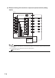
5.3 Part Identification Nomenclature
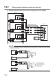
When the phase Z of the encoder is connected to the phase Z pulse input terminals (Z1, Z2), pulses are counted per
rotation of the encoder. Therefore, lighting of the Z_CH1 to CH2 LEDs
may be missed.
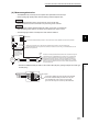
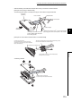
(1) Connector for external wiring
The connectors for use with the QD65PD2 should be purchased separately by the user.
The following tables show the connector types and the crimp-contact tool.
(a) Precautions
• Use copper wires having temperature rating of 75°C or more for the connectors.
• When required, use UL-approved connectors.
(b) Connector types
*1
*1 The A6CON3 (pressure-displacement type, straight out) connector cannot be used for the QD65PD2.
(c) Crimp-contact tool
Number Name Description
2)
Connectors for external devices (40
pins)
Connectors for encoders, controllers, and others.
Refer to the following section for the terminal diagram.
Page 90, Section 3.5.1
3) Serial No. display Displays the serial No. of the QD65PD2.
Type Model name Applicable wire size
Soldering type
(straight out)
A6CON1
0.3mm
2
(22AWG) (stranded)
Crimp-contact type
(straight out)
A6CON2
0.088mm
2
to 0.24mm
2
(28 to 24 AWG) (stranded)
Soldering type
(straight out/diagonal out)
A6CON4
0.3mm
2
(22AWG) (stranded)
Type Model name Applicable wire size Contact
Crimp-contact tool FCN-363T-T005/H
0.088mm
2
to 0.24mm
2
(28 to 24 AWG)
FUJITSU COMPONENT LIMITED
http://www.fcl.fujitsu.com/en/