
User`s manual


173
CHAPTER 5 SETTINGS AND PROCEDURE BEFORE OPERATION
5
5.4 Wiring
5.4.1 Wiring precautions
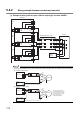
• Take the following noise reduction measures when wiring a connector for external devices.
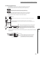
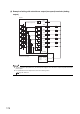
[Example of wiring using a shielded cable]
The following figure shows an example of wiring for noise reduction using the A6CON1.
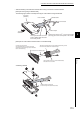
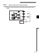
[Example of a noise reduction measure taken on a shielded cable]
Assembling A6CON1
From controller
To external output
Ground the FG wire of 2mm
2
or more at the shortest
(Securely ground to the control panel on the encoder
From encoder
Shielded cable
Connector
(A6CON1)
To the
QD65PD2
The length between the connector
and the shielded cables should be
the shortest possible.
Take off the insulating tube of each shield and electrically connect
the shield of the cables with conductive tapes.
Covered with an insulating tape
Take a shield out from any of the shielded cables,
and solder it to the FG wire.
Coat the connect pins with
heat-shrinkable tubes to protect signal lines.
(Exposure of signal lines may cause malfunction
due to static electricity.)
Cover the cables including the
conductive tape with heat-shrinkable tube.