
User`s manual


174
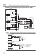
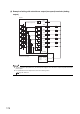
5.4.2 Wiring example (between module and encoder)
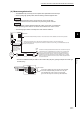
(1) Example of wiring with an open collector output type encoder (24VDC)
When wiring the QD65PD and an encoder, separate power cables and signal cables. The following figure shows examples.
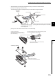
● Example of correct wiring
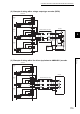
● Example of incorrect wiring
External
power
supply
QD65PD2
Phase
A
Phase
B
Phase
Z
Shielded twisted pair cable
Encoder
0V
A18
B18
A19
B19
B17
B15
A16
B16
A17
A15
A13
B13
A14
B14
B12
DIF
5V
12V
24V
COM
DIF
5V
12V
24V
COM
DIF
5V
12V
24V
COM
1.5k900200176
3.3k
1.5k900200176
3.3k
1.5k900200176
3.3k
24V
OUT
24V
OUT
24V
OUT
E
24VDC
Shielded twisted pair cable
Pulse input
24V
QD65PD2
COM
External
power
supply
24VDC
0V
Encoder
OUT
+24V
0V
E
Shielded twisted pair cable
Pulse input
24V
QD65PD2
COM
External
power
supply
24VDC
0V
Encoder
OUT
+24V
0V
E
Since a current flows through
the shielded twisted pair cables
in the same direction, canceling
effect does not work and pulses
become susceptible to
electromagnetic induction.