
User`s manual


257
CHAPTER 8 TROUBLESHOOTING
8
8.4 Troubleshooting by Symptoms
8.4.1 When counting (measurement) does not start, or when not counted (measured) correctly
How to fix pulse form
This portion describes how to fix pulse waveform by dummy resistance that can be used for noises from outside or
distortion of pulse waveform. To fix the pulse waveform effectively, increase load current inside cables by applying
dummy resistance of several hundreds ohms (/several W) between the pulse input terminals that are connected to the
encoder.
The greater the load current, the more effective this method is.
● Effect
• When the distance between the encoder and the QD65PD2 is long, distortion of waveform gets fixed and the
pulse waveform becomes stable.
• When the pulse waveform is distorted due to noses from outside, taking the method above stabilizes pulse
waveform; Distortion of pulse waveform by noise can be reduced.
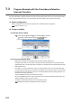
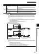
● Example of dummy resistance at 24VDC.
● How to choose dummy resistance
An example of how to choose the resistance amount and rated-standard electricity of dummy resistance is indicated
below. If load current is set to approximately 35mA, the resistance amount and the rated-standard electricity become as
follows.
• How to calculate resistance amount (at 24VDC)
Calculation: R = V I = 24V 35mA = 680
• How to calculate rated-standard electricity (at 24VDC)
Calculation: P1 = V × I = 24V × 35mA = 0.84W (approximately 1W)
Calculation including margin: P2 = P1 × 2 = 0.84W × 2 = 1.68W (approximately 2W)
• Result: Put dummy resistance of 680 (/2W)between the pulse input terminals.
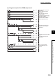
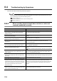
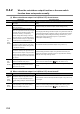
Noise
reduction
measures
Are the shielded twisted pair cables used for
pulse input wiring?
Use the shielded twisted pair cables for pulse input wiring.
Have measures against noise been taken to
the adjacent devices and inside the control
panel?
Take noise reduction measures such as attaching a CR surge suppressor to
the magnet switch.
Is the distance between the high voltage
equipment and pulse input line kept enough?
Bundle the pulse input lines and put them in a single tube, and keep a
distance of 150mm or more with the power line even inside the control panel.
Does any noise come from the grounded part
of the QD65PD2.
Separate the grounding cable of the QD65PD2 from the grounded part.
If the QD65PD2 case touches to the grounded part, separate it.
Check item Corrective action
Shielded twisted pair cable
QD65PD2
B19
A19
B18
SV
12V
A18
DIF
24V
COM
3.3k
176 200 900 1.5k
B17
A17
B16
A16
5V
12V
B15
DIF
24V
COM
3.3k
176 200 900 1.5k
A15
Put dummy resistance of several hundreds
ohms (/several W) between the pulse input
terminals, 24V and COM.
Phase A
Phase B