
User`s manual


31
CHAPTER 3 SPECIFICATIONS
3
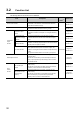
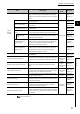
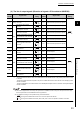
3.2 Function List
*1 The operation mode can be set using the switch setting. For details, refer to the following:
Page 180, Section 6.2
Counter
function
selection
This function executes the counter function selection using
both the sequence program and the function input terminal
(FUNC1) of the connector for external devices, or using either
of them.
Page 131,
Section 4.6
Count disable function
This function stops counting pulses while CH1 Count enable
command (Y06) is on.
Normal mode
Page 132,
Section 4.7
Latch counter function
This function latches the count value, and stores it to the
buffer memory.
Page 129,
Section 4.5.2
Sampling counter function
This function counts pulses that are input during the preset
sampling period.
Page 133,
Section 4.8
Periodic pulse counter
function
This function stores the current value and difference value to
the corresponding buffer memories by the preset cycle time.
Page 136,
Section 4.9
Periodic interrupt
function
This function outputs an interrupt signal to the CPU module
and starts an interrupt program by the cycle time using the
periodic pulse counter function.
Page 139,
Section 4.9.1
Count disable/preset/
replace function
According to the status change of the function input terminal
(FUNC1) of the connector for external devices, this function
executes the count disable function and preset/replace
function without switching the functions.
Page 141,
Section 4.10
Latch counter/preset/
replace function
According to the status change of the function input terminal
(FUNC1) of the connector for external devices, this function
executes the latch counter function and preset/replace
function without switching the functions.
Page 143,
Section 4.11
Internal clock function
This function does the count based on the clock incorporated
in the QD65PD2.
Normal mode
Page 145,
Section 4.12
Frequency measurement function
This function counts the pulses of the pulse input terminals in
phase A and B, and automatically calculates the frequency.
Frequency
measurement
mode
Page 146,
Section 4.13
Rotation speed measurement function
This function counts the pulses of the pulse input terminals in
phase A and B, and automatically calculates the rotation
speed.
Rotation
speed
measurement
mode
Page 150,
Section 4.14
Pulse measurement function
This function measures the function input terminal (FUNC1) of
the connector for external devices or the latch counter input
terminal (LATCH1), and calculates the ON width.
Pulse
measurement
mode
Page 155,
Section 4.15
PWM output function
This function outputs the specified PWM waveform from any
coincidence output terminals.
PWM output
mode
Page 1
59,
Section 4.16
General input function
This function stores the status of the general input 1 to 6
terminals (IN1 to IN6) of the connector for external devices to
the input signal (X signal).
Common to
all modes
Page 162,
Section 4.17
General output function
This function stores the status of the general output 1 to 8
terminals (OUT1 to OUT8) of the connector for external
devices to the output signal (Y signal).
Page 162,
Section 4.18
Module error collection function
When an error occurs in the QD65PD2, this function sends
the error description to the CPU module. The error description
is stored to the memory inside the CPU module as a module
error collection.
Page 164,
Section 4.19
Item Description
Operation
mode
*1
Reference