
User`s manual


32
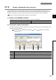
3.3 I/O Signals to the CPU Module
The following table lists the QD65PD2 I/O signals to the CPU module.
The I/O numbers (X/Y) described in this chapter or later are for the case when the QD65PD2 are mounted on the I/O
slot No.0 of the main base unit.
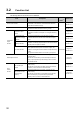
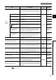
3.3.1 List of I/O signals
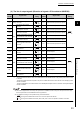
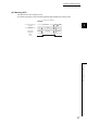
(1) The list of input signals (Direction of signals: QD65PD2 to CPU module)
The reserved signals above are used by the system and not available for users. If they are used (turned on and off) by users,
the performance of the QD65PD2 cannot be guaranteed.
I/O
number
Signal name
I/O
number
Signal name
X00 Module ready X10 Coincidence output 1
X01 Operating condition settings batch-changed X11 Coincidence output 2
X02
CH1
Reserved X12 Coincidence output 3
X03 Reserved X13 Coincidence output 4
X04 Reserved X14 Coincidence output 5
X05
External preset/replace (Z Phase) request
detection
X15 Coincidence output 6
X06 Reserved X16 Coincidence output 7
X07 Reserved X17 Coincidence output 8
X08 Cam switch function execution/PWM output X18 General input 1
X09
CH2
Reserved X19 General input 2
X0A Reserved X1A General input 3
X0B Reserved X1B General input 4
X0C
External preset/replace (Z Phase) request
detection
X1C General input 5
X0D Reserved X1D General input 6
X0E Reserved X1E Error
X0F Cam switch function execution/PWM output X1F Warning