
User`s manual


35
CHAPTER 3 SPECIFICATIONS
3
3.3 I/O Signals to the CPU Module
3.3.2 Details on input signals
• Buffer memories for the data classification Md1 (except for the Md1 associated with an error or a warning)
are not updated when this signal is OFF.
To check the data classification and corresponding buffer memories, refer to the following:
Page 42, Section 3.4.1
• When this signal is OFF, buffer memories for the data classification Cd2 except CH1 Error reset command
(Un\G1480) are disabled. (The values of these buffer memories remain set to Reset (1
H
) or Requested (1
H
),
and will be enabled when this signal turns on.
• If output signal Y02 to Y1F is ON when this signal turns on, Y02 to Y1F are regarded as having risen after
the signal, and the operation is performed accordingly. (The operation is performed with Y02 to Y1F
regarded as being OFF when this signal turns on.)
• When this signal turns on, a count value is replaced by the preset value at the rise of the coincidence output
No.1 and No.2, the memories to activate the preset/replace (at coincidence output) function.
Note that the value is replaced on the condition that coincidence output is selected in "Comparison output
setting value" in the switch setting and normal mode is selected in "Operation mode setting".
• When the setting values in buffer memories or in the switch setting are set beyond the setting range and an
error is detected, this signal does not turn on even by turning on and off Operating condition settings batch-
change command (Y01).
In that case, turn off and on, and then off Operating condition settings batch-change command (Y01) after
the error cause is removed. Keep the ON time 2ms or more.
(3) CH1 External preset/replace (Z Phase) request detection (X05)
• This signal turns on when a count value is replaced with the preset value by the phase Z input terminal (Z1)
of the connector for external devices.
Note that this signal does not turn on when Z phase (Preset) trigger setting (b0, b1) in CH1 Phase Z setting
(Un\G1000) is set to 3: On.
• This signal turns off by CH1 External preset/replace (Z Phase) request detection reset command (Y05).
• The value is not replaced while this signal is ON.
• This signal does not turn on when External preset/replace (Z Phase) request detection setting (b4) in CH1
Phase Z setting (Un\G1000) is set to 1: The signal remains off when the preset/replace function is
performed. This signal turns on only when b4 is set to 0: The signal turns on when the preset/replace
function is performed.
• This signal responds with up to 2ms delay.
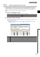
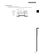
• The following figure shows the case when Z phase (Preset) trigger setting (b0, b1) in CH1 Phase Z setting
(Un\G1000) is set to 0: Rise.
(4) CH1 Cam switch function execution/PWM output (X08)
• This signal turns on while the cam switch function is activated.
• This signal turns on when PWM is output.
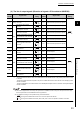
100
0 100
Phase Z input terminal
(Z1)
t *
CH1 External preset/replace
(phase Z) request detection
(X05)
CH1 External preset/replace (phase Z)
request detection reset command
(Y05)
Operation by the QD65PD2
Operation by the sequence program
OFF
ON
ON
ON
OFF
OFF
* t 2ms
CH1 Present value
(Un\G1050, Un\G1051)
CH1 Preset value
(Un\G1014, Un\G1015)