
User`s manual


36
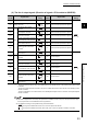
(5) Coincidence output 1 to 8 (X10 to X17)
• This signal turns on when a count value satisfies the comparison condition of the coincidence output function
or cam switch function.
(To check the conditions on which this signal turns on or off, refer to the following:)
Page 107, Section 4.3
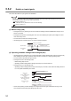
• When using the coincidence output function, select the comparison conditions from Coincidence output, In-
range output, and Not-in-range output in Coincidence output condition setting (Un\G0).
• This signal responds with up to 2ms delay.
• The following figure shows the case when Coincidence output 1 (b0, b1) in Coincidence output condition
setting (Un\G0) is set to 1: In-range output, with the coincidence output function used.
(6) General input 1 to 6 (X18 to X1D)
• Set input values to the general input 1 to 6 terminals (IN1 to IN6) for the external input.
• This signal turns on when ON voltage is applied to the general input 1 to 6 terminals (IN1 to IN6) for the
external input.
• This signal responds with up to 2ms delay.
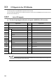
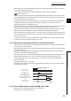
(7) Error (X1E)
• This signal turns on when an error occurs.
• Turn off this signal by Error reset command (Un\G1480) after eliminating the error cause.
Coincidence output 1
(X10)
ON
OFF
0 1 999 1000 2000 2001
1000
2000
Lower limit value (coincidence output 1)
(Un\G120, Un\G121)
Upper limit value (coincidence output 1)
(Un\G122, Un\G123)
CH1 Present value
(Un\G1050, Un\G1051)
Operation by the QD65PD2
0 1100 0
Error
(X1E)
Operation by the QD65PD2
OFF
ON
CH1 Error reset command
(Un\G1480)
CH1 Latest error code
(Un\G1460)
Normal (0) Error (1) Normal (0)
Error status
(Un\G953.b0)
Not reset (0
H)
Reset
(1H)
Not reset
(0H)