
User`s manual


55
CHAPTER 3 SPECIFICATIONS
3
3.4 Buffer Memory Assignment
3.4.1 List of buffer memory assignment
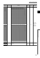
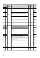
(2) Different from each channel (Un\G1000 to Un\G5999)
Address
(decimal
notation)
Data
classification
Contents
Default
value
*1
Read/
write
*2
Remarks
CH1 CH2
1000 1500
Pr1
CH Phase Z setting
0R/W
Use it for the
preset/replace
function.
1001 1501 CH Periodic interrupt setting
Use it for the
periodic pulse
counter
function.
1002 1502
System area
•••
•••
1009 1509
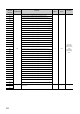
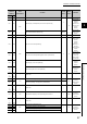
1010 1510
Pr2
CH Ring counter lower limit value (L)
*3
0
R/W
Use it for the
ring counter
function.
1011 1511
CH Ring counter lower limit value (H)
*3
1012 1512
CH Ring counter upper limit value (L)
*3
1013 1513
CH Ring counter upper limit value (H)
*3
1014 1514
CH Preset value (L)
*3
Use it for the
preset/replace
function.
1015 1515
CH Preset value (H)
*3
1016 1516 CH Time unit setting (sampling counter/periodic pulse counter) Use it for the
sampling
counter
function or the
periodic pulse
counter
function.
1017 1517 CH Cycle setting (sampling counter/periodic pulse counter) 1
1018 1518
System area
•••
•••
1019 1519
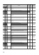
1020 1520 Cd2 CH Setting change request (sampling counter/periodic pulse counter) 0 R/W
Use it for the
sampling
counter
function or the
periodic pulse
counter
function.
1021 1521 System area