
User`s manual

69
CHAPTER 3 SPECIFICATIONS
3
3.4 Buffer Memory Assignment
3.4.2 Details of the buffer memory
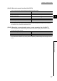
(10)Cam switch function, step No.1 to No.16 setting (coincidence output 1)
(Un\G202 to Un\G233)
• Use these memories to set the comparison values to select whether on signal or off signal should be output.
The values are set to step No.1 to No.16 for coincide output 1.
• This memory corresponds to Coincidence output 1.
To check the buffer memory addresses corresponding to Coincidence output 2 to 8, refer to the following:
Page 42, Section 3.4.1
• The setting range is between -2147483648 and 2147483647 in 32-bit signed binary format.
• The setting values are enabled by turning off and on CH1 Cam switch function/PWM output start command
(Y08).
• The default values are 0.
● Given that a step No. is m, set a smaller number to the step No.m than to the step No. (m+1). When the greater number
is set, an error (error code:3n1 to 3n5)
*1
will be detected.
*1 indicates the number of channel with the error, and n indicates the number of Coincidence output with the error.
● Set the values of Step No. that satisfy the following formula so that the pulse input speed is not exceed the permissible
speed.
Pulse input speed (pps) 1000 (Setting values of the step No. (m+1) for Coincidence output 1 to 8) - (Setting values of the step No.m for
Coincidence output 1 to 8)
If the values do not satisfy the formula, the count values are not detected in the minimum unit, and on or off signals are
not output.
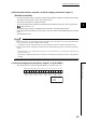
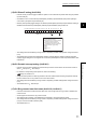
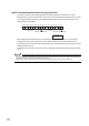
(11)Channel assignment (coincidence output 1 to 8) (Un\G950)
• This memory stores the channel assignment status for Coincidence output 1 to 8.
b15 b14 b13 b12 b11 b10 b9 b8 b7 b6 b5 b4 b3 b2 b1 b0
0: Not assigned
1: CH1
2: CH2
Coincidence
output 1
Coincidence
output 8
Coincidence
output 7
Coincidence
output 6
Coincidence
output 5
Coincidence
output 4
Coincidence
output 3
Coincidence
output 2