
User`s manual

87
CHAPTER 3 SPECIFICATIONS
3
3.4 Buffer Memory Assignment
3.4.2 Details of the buffer memory
(68)CH1 Cycle setting (PWM output) (Un\G1304, Un\G1305)
• Use these memories to set a cycle for the PWM output.
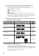
• Setting range varies depending on which Coincidence output is set to 1: Assigned in CH1 PWM output
assignment (Un\G1300).
• The setting values are enabled by turning off and on CH1 Cam switch function/PWM output start command
(Y08).
• The default value is 50.
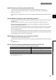
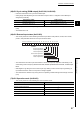
(69)CH1 External input status (Un\G1450)
• This memory stores the values indicating the external input status of the phase Z, function, latch counter,
phase A, and phase B as well as the count-up/count-down status.
• The stored value of Function input status remains 0: Off or count-up when "Operation mode setting" in the
switch setting is set to Frequency Measurement Mode, Rotation Speed Measurement Mode, or PWM Output
Mode.
• With Negative Logic being set in the Function Input Logic Setting or Latch Counter Input Logic Setting, its
input status becomes 0: Off or count-up when a voltage is applied.
• The stored value is cleared to 0 by turning off and on Operating condition settings batch-change command
(Y01).
(70)CH1 Operation mode (Un\G1451)
• This memory stores the value indicating the current operation mode.
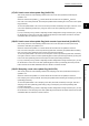
Coincidence output Setting range
Coincidence output 1 or 2 50 to 10000000 (0.1µs per unit)
Coincidence output 3 to 8 5000 to 10000000 (0.1µs per unit)
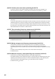
Operation mode Value to be stored
Normal Mode
0
H
Frequency Measurement Mode
1
H
Rotation Speed Measurement Mode
2
H
Pulse Measurement Mode
3
H
PWM Output Mode
4
H
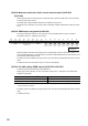
b15
0
b14
0
b13
0
b12
0
b11
0
b10
0
b9
0
b8
0
b7
0
b6
0
b5 b4 b3 b2 b1 b0
Fixed to 0.
0: Off or count-up
1: On or count-down
Phase B input status
Phase A input status
Latch counter input status
Function input status
Phase Z input status
Count-up/count-down