
User`s manual


91
CHAPTER 3 SPECIFICATIONS
3
3.5 Specifications of I/O Interfaces with External Devices
3.5.2 List of I/O signal details
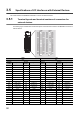
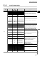
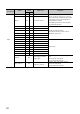
3.5.2 List of I/O signal details
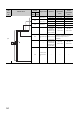
The following table lists the signals for the QD65PD2 connectors for external devices.
I/O
classification
Symbol
Terminal
number
Signal name Description
CON1 CON2
Input
A1-24V, A2-24V B19 Phase A pulse input 24V (+)
This signal inputs + (plus) side of phase A pulse.
A1-12V, A2-12V A19 Phase A pulse input 12V (+)
A1-5V, A2-5V B18 Phase A pulse input 5V (+)
A1-DIF, A2-DIF A18
Phase A pulse differential
input (+)
A1-COM,
A2-COM
B17
Phase A pulse input
common (-)
This signal inputs - (minus) side of phase A pulse.
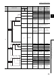
B1-24V, B2-24V A17 Phase B pulse input 24V (+)
This signal inputs + (plus) side of phase B pulse.
B1-12V, B2-12V B16 Phase B pulse input 12V (+)
B1-5V, B2-5V A16 Phase B pulse input 5V (+)
B1-DIF, B2-DIF B15
Phase B pulse differential
input (+)
B1-COM, B2-COM A15
Phase B pulse input
common (-)
This signal inputs - (minus) side of phase B pulse.
Z1-24V, Z2-24V B14 Phase Z input 24V (+) This signal inputs + (plus) side of phase Z.
Turn on this signal to replace a count value by the
external signal. By doing so, the count value is
replaced with the preset value on the condition that
Phase Z (preset/replace) trigger setting (b0, b1) in
CH1 Phase Z setting (Un\G1000) is set to 0: Rise.
Z1-12V, Z2-12V A14 Phase Z input 12V (+)
Z1-5V, Z2-5V B13 Phase Z input 5V (+)
Z1-DIF, Z2-DIF A13 Phase Z differential input (+)
Z1-COM, Z2-COM B12 Phase Z input common (-) This signal inputs - (minus) side of phase Z.
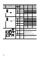
FUNC1-24V,
FUNC2-24V
A12 Function input 24V (-)
Turn on this signal to perform the selected counter
function by the external signal.
FUNC1-12V,
FUNC2-12V
B11 Function input 12V (-)
FUNC1-5V,
FUNC2-5V
A11 Function input 5V (-)
LATCH1-24V,
LATCH2-24V
A10 Latch counter input 24V (-)
Turn on this signal to latch an count value by the
external signal. By doing so, the count value is
latched and stored in buffer memories.
LATCH1-12V,
LATCH2-12V
B09 Latch counter input 12V (-)
LATCH1-5V,
LATCH2-5V
A09 Latch counter input 5V (-)
CTRLCOM-1,
CTRLCOM-2
B10 Control input common (+)
Common for latch counter input
Common for function input
It is separated from each channel.
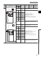
IN1 A03 General input 1 (-)
General input (high speed)
IN2 B02 General input 2 (-)
IN3 A02 General input 3 (-)
General input (low speed)
IN4 A03 General input 4 (-)
IN5 B02 General input 5 (-)
IN6 A02 General input 6 (-)
IN_COM24V B03 General input common (+)
24V common for general input
It is common between channels.