Positioning Module Software Package Operating Manual Mitsubishi Programmable Logic Controller SW0D5C-QD75P-E
• SAFETY INSTRUCTIONS • (Always read these instructions before using this equipment.) Before using this product, please read this manual and the relevant manuals introduced in this manual carefully and pay full attention to safety to handle the product correctly. The instructions given in this manual are concerned with this product. For the safety instructions of the programmable controller system, please read the CPU module user's manual.
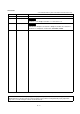
REVISIONS * The manual number is given on the bottom left of the back cover. Print Date Feb., 2000 May., 2000 * Manual Number Revision SH (NA)-080057-A First edition SH (NA)-080057-B Correction Section 4.1, 7.4, Chapter 9, Section 11.1.4, Section 11.5 Oct., 2000 SH (NA)-080057-C Correction CONTENTS, Chapter 1, Section 2.1, Chapter 6, Section 6.1, Section 7.1, Section 8.2.1, Chapter 9, Section 10.
Recommendation of Software Registration After you have acknowledged the contents of the "Software Usage Agreement" supplied with the product, fill out the "Software Registration Card" and return it to us to obtain the following services. We will send you the user ID and "Registration Confirmation Card" after making the user registration of the "Software Registration Card" you returned. (No extra charge is needed for registration.
INTRODUCTION Thank you for choosing the Mitsubishi MELSEC-Q Series General-Purpose Programmable Logic Controller. Before using the product, please read this manual carefully to use the equipment to its optimum. SAFETY INSTRUCTIONS.............................................................................................................................A- 1 REVISION ...............................................................................................................................................
.3 Saving the Project .................................................................................................................................... 6- 6 6.4 Closing the Project ................................................................................................................................... 6- 7 6.5 Deleting the Project.................................................................................................................................. 6- 8 6.
10.4.3 Speed change test ........................................................................................................................ 10-26 10.4.4 OPR test ........................................................................................................................................ 10-28 10.4.5 JOG/MPG operation test............................................................................................................... 10-30 11. USEFUL FUNCTIONS 11- 1 to 11-38 11.
About Manuals The following manuals are related to this product. Refer to the following table and request the required ones. Related Manuals Manual Number Manual Name (Model Code) Type QD75P1/QD75P2/QD75P4, QD75D1/QD75D2/QD75D4 Positioning Module User's Manual SH-080058 Describes the system configuration, performance specifications, functions, handling, pre-operation (13JR09) procedures and troubleshooting of the QD75P1/QD75P2/QD75P4 and QD75D1/QD75D2/QD75D4.
How to Use This Manual BASIC OPERATION PURPOSE Operation to be performed until the actual operation screen appears. Purpose of operation explained in each chapter, section or paragraph. 8.2.2 M code comment PURPOSE Set comments to M codes which are required for control exercised in synchronization with positioning. M code comments are data which can be saved only on the peripheral device. Up to 50 comments can be set for each axis. BASIC OPERATION 1.
In addition, there are also the following explanations. HELPFUL OPERATION Describes application operation if there are multiple purposes and the basic operation and display/setting data do not provide enough information. HELPFUL CORRECTIVE ACTIONS Explains basic corrective actions if monitored data is abnormal or a test cannot be made. Provides information relevant to that page, e.g. the items you should be careful of and the functions you should know.
About the Generic Terms and Abbreviations The following generic terms and abbreviations for the positioning software packages, positioning modules, etc. are used in this manual.
1. OVERVIEW MELSEC-Q 1. OVERVIEW 1 This manual describes the functions and operating procedures of positioning module software package (hereinafter referred to as "SW D5C-QD75P-E"). SW D5C-QD75P-E is a positioning module software package which can perform the following functions via the QCPU, Q corresponding serial communication module or Q corresponding MELSECNET/H network remote I/O module.
1. OVERVIEW MELSEC-Q 1.1 Features (1) Concurrent editing of multiple projects Capable of opening multiple projects simultaneously, this software allows you to easily edit the positioning data and block start data to be utilized by copying and pasting.
1. OVERVIEW MELSEC-Q (3) Simplified sequence program by automatic refresh setting Automatic refresh setting is made to automatically read the following values stored in QD75 buffer memory to the QCPU devices. • Feed present value • Machine feed value • Feed speed • Error No. • Warning No. • Enable M code Automatic refresh setting reduces the number of FROM instructions used to read the buffer memory storage values, facilitating creation and debugging of sequence programs.
1. OVERVIEW MELSEC-Q (5) Setting of optimum positioning data without complicated calculation Positioning data can be set by sub arc setting and automatic axis speed setting. Sub arc setting generates from the specified two linear interpolation control data the circular interpolation control data in which the angle between two linear paths is converted into a circular arc (curve) path.
1. OVERVIEW MELSEC-Q (8) Compatible with multiple PLC system On SW D5C-QD75P-E (Version 30D or later), setting the control PLC type and PLC No. of the QD75 to communicate with in Connection Setup (refer to Section 7.1) allows communication to be made with any QD75. PLC PLC PLC PLC No. 1 No. 2 No. 3 No. 4 QCPU QCPU QCPU QCPU QD75 QD75 QD75 1 2 3 PLC No. of control PLC In Connection Setup, specify the control PLC type and PLC No. of the QD75 to communicate with.
1. OVERVIEW MELSEC-Q 1.2 Manual Makeup This manual is made up of 11 chapters and appendices. This manual assumes that SW D5C-QD75P-E is used to perform steps from positioning system checking to operation in the following procedure. Step 1: Install and wire the positioning system.
1. OVERVIEW MELSEC-Q (From the preceding page) Step 5: Set and write data to the positioning module. Refer To • Set the parameters appropriate for the positioning system and control. • Set the positioning data and M code comments. Chapter 8 • Check the positioning data on the simulation screen. • Make the corresponding setting if block start data and/or condition data is required. • Make error check to check the parameters, positioning data and block start data settings.
1. OVERVIEW MELSEC-Q 1.3 Additions/Modifications Function according to SW0D5C-QD75P-E Versions Additions/Modifications Functions for each Versions of SW0D5C-QD75P-E are given below. Function Versions of SW0D5C-QD75P-E 1 2 Reference Version 30D or later Version 20C or below Yes No Section 7.1 Yes No Section 8.1 Yes No Section 10.2.4 Connection Setup • Addition of PLC No.
2. SYSTEM CONFIGURATION MELSEC-Q 2. SYSTEM CONFIGURATION 2.
2.
2. SYSTEM CONFIGURATION MELSEC-Q • Do not connect a peripheral device to the Q corresponding serial communication module by multidrop link. • Concurrent use of this product on multiple personal computers is illegal. Therefore, this product may only be used on the personal computer specified in the software registration card. However, to prepare for any unexpected situation, e.g. hard disk crash of the personal computer, the license key FD is designed to be installable up to five times.
2. SYSTEM CONFIGURATION MELSEC-Q (c) Connection to Q corresponding serial communication module The specifications of the RS-232 cable connector are indicated below.
2. SYSTEM CONFIGURATION MELSEC-Q 2.2 Operating Environment Operate the system in the following environment. Item Peripheral device System software Description Personal computer with Pentium 133MHz or more (recommended) CPU and Windows R 95 upwards. Microsoft R Windows Windows R 98 Operating System (English version) or Microsoft WindowsNT Required memory R R R 95 Operating System (English version), Microsoft R Workstation 4.
2.
3. FUNCTION LIST MELSEC-Q 3. FUNCTION LIST 3.1 Function List (1) Function list The main functions of SW D5C-QD75P-E are listed.
3. FUNCTION LIST MELSEC-Q Function Diagnosis Checking connect Description Initializes the QD75 and displays signals from external devices. Also tests initial operation by JOG operation. Waveform display Traces the speed command for a given time and displays the waveform data relative to the time axis. Locus display Traces the position command or real value for a given time and displays the track data of the axes.
3. FUNCTION LIST MELSEC-Q 3.2 Menu list The menu bar drop-down menus are listed below.
3.
4. INSTALLATION AND UNINSTALLATION MELSEC-Q 4. INSTALLATION AND UNINSTALLATION This chapter describes how to install and uninstall SW D5C-QD75P-E. 4.1 Installation Installation procedure START Install SW D5C-QD75P-E. Register your name and company name. Refer to Section 4.1 (1). Register the product I/D. Prepare the FD drive. 1 4 Install the license key FD. Make SW D5C-QD75P-E valid. Refer to Section 4.1 (2). Store the license key FD. Start the application.
4. INSTALLATION AND UNINSTALLATION MELSEC-Q (1) Installing SW D5C-QD75P-E The following explains how to install SW D5C-QD75P-E. • Before starting installation, close all other applications running on Microsoft Windows Operating System. • When the Operating System is Microsoft WindowsNT Workstation 4.0 Operating System, log on as a user who has the attribute of an administrator (for computer management). R R R R 1) Start Explorer and click the drive where the disk is inserted. Double-click "Setup.
4. INSTALLATION AND UNINSTALLATION MELSEC-Q (From the preceding page) 2) Type your name and company name, and click the "Next>" button. As the confirmation dialog box appears, follow the messages and perform operation. 3) Enter the product ID and click the "Next>" button. The product ID is given on the "Software Registration Card". 4) Specify the installation destination folder. After specifying the installation destination folder, click the "Next>" button. It defaults to "C:\MELSEC".
4. INSTALLATION AND UNINSTALLATION MELSEC-Q (From the preceding page) 5) This completes installation. Now install the license key FD and set the product to valid status. When the message shown on the left appears, Windows must be restarted. R • If installation failed at any point in the above procedure, uninstall and reinstall the program. Installing SW D5C-QD75P-E registers the icon as shown below.
4. INSTALLATION AND UNINSTALLATION MELSEC-Q (2) Installing the license key FD The license key FD is designed to make SW D5C-QD75P-E valid. After installing SW D5C-QD75P-E, install the license key FD to make SW D5CQD75P-E startable. 1) Start Explorer and click the drive where the disk is inserted. Double-click "Setup.exe". To display Explorer, choose [Start] [Programs] [Windows Explorer]. 2) Click the picture of the lock. 3) Click the "Close" button.
4. INSTALLATION AND UNINSTALLATION MELSEC-Q 4.2 Uninstallation This section explains the operation for removing SW D5C-QD75P-E from the hard disk. Uninstallation procedure START Uninstall the license key FD. Make SW Uninstall SW D5C-QD75P-E invalid. D5C-QD75P-E. Refer to Section 4.2 (1). Refer to Section 4.2 (2). FINISH • Uninstallation requires the same license key FD as used for installation.
4. INSTALLATION AND UNINSTALLATION MELSEC-Q (1) Uninstalling the license key FD 1) Start Explorer and click the drive where the license key FD is inserted. Double-click "Setup.exe". To display Explorer, choose [Start] [Programs] [Windows Explorer]. 2) Click the picture of the open lock. 3) Click the "Close" button. (When the picture of the closed lock appears, the product is made invalid and can be uninstalled.
4. INSTALLATION AND UNINSTALLATION MELSEC-Q (2) Uninstalling SW D5C-QD75P-E 1) Double-click "Add/Remove Programs" on the Control Panel. To display the Control Panel, choose [Start] [Settings] [Control Panel]. 2) Choose "SWnD5-QD75P". 3) Confirm that SW D5C-QD75P-E will be removed. Click "Yes" to start uninstallation. Click "No" to return to the previous screen. (To the next page) Components indicate the installed icon and file.
4. INSTALLATION AND UNINSTALLATION MELSEC-Q (From the preceding page) 4) If the left screen has appeared, click the "No to All" button. If you choose "Yes" or "Yes to All", the shared files for other MELSEC software packages are removed. To remove only SW D5C-QD75P-E, therefore, click the "No to All" button. 5) When the "Uninstall completed" message appears, click the "OK" button. The completed message indicates that uninstallation is complete.
4. INSTALLATION AND UNINSTALLATION MELSEC-Q 4.3 Starting SW D5C-QD75P-E This section explains how to start SW D5C-QD75P-E from the start menu. 1) Move the cursor from [Start] [MELSEC Application]. 2) Click [QD75WIN]. 3) SW D5C-QD75P-E starts.
4. INSTALLATION AND UNINSTALLATION MELSEC-Q 4.4 Exiting SW D5C-QD75P-E This section describes how to exit SW D5C-QD75P-E. (1) Menu-driven exit method Click the [Project] [Exit] menu. SW D5C-QD75P-E ends. (2) Title bar-driven exit method Click and choose [Close]. Alternatively, click at the right end of the title bar. • In the online status such as the monitor or test mode, you cannot exit SW D5CQD75P-E. In any of the following cases, end the program after choosing the offline status.
4.
5. SCREEN MAKEUP AND BASIC OPERATIONS MELSEC-Q 5. SCREEN MAKEUP AND BASIC OPERATIONS This chapter explains the screen makeup and the display selection, window arrangement and other operations of SW D5C-QD75P-E. 5.1 Screen Makeup and Display Selection This section provides the screen makeup of SW D5C-QD75P-E.
5. SCREEN MAKEUP AND BASIC OPERATIONS MELSEC-Q 5.2 Basic Operations (1) Basic operation for project tree view (a) Opening a window The currently open project appears on the project tree view. Double-click the project name or click to show its functions. (From the keyboard, choose the project name and press the " " key.) Double-click the function name or click to show the window types. (From the keyboard, choose the function name and press the " " key.) Double-click the window name to open that window.
5. SCREEN MAKEUP AND BASIC OPERATIONS MELSEC-Q (2) Basic operation for dialog boxes 1) Tab Click the setting item name to select. 1) Tab 2) Text box 2) Text box Type numerals/characters. 3) Command button 3) Command button Click this button when executing "OK", "Cancel" etc., or when displaying the dialog box. 4) Radio button Click to choose one item among multiple choices. 4) Radio button 5) List box 6) Check box 5) List box Click to list choices, then click the item to be chosen.
5. SCREEN MAKEUP AND BASIC OPERATIONS MELSEC-Q (3) Moving the focus from the keyboard Use the "Alt" key to move the focus to the drop-down menu. Use the "F6" key to move the focus between the project tree view and window (edit, monitor, trace, checking connect). (4) Shortcut key list The following shortcut keys can be used with SW D5C-QD75P-E.
6. PROJECT CREATION MELSEC-Q 6. PROJECT CREATION A project is a collection of parameters, positioning data and block start data. Parameters (Axis #1 to #4) There are basic parameters 1, basic parameters 2, extended parameters 1, extended parameters 2, OPR basic parameters and OPR extended parameters. Project Positioning data (Axis #1 to #4) Data used to set the control data such as positioning control method and addresses. Data No. 1 to 600 can be set for each axis.
6. PROJECT CREATION MELSEC-Q 6.1 Creating a New Project Set the QD75 model used to create a new project and the project items. 1) Click the [Project] [New Project] menu ( ). 2) Click the "Reference" button of the QD75 type in the [New Project] dialog box. 3) Choose the Select type and Select Axis radio buttons. 4) Click the "OK" button. 5) Set the project save path. The project save path defaults to C:\MELSEC\QD75P. When changing it, refer to "HELPFUL OPERATION (PART 1)" in this section.
6. PROJECT CREATION MELSEC-Q HELPFUL OPERATION (PART 1) You can perform the operation of changing the project save path while simultaneously checking the project tree. In step 5) on the preceding page, click the Project file set "Reference" button. When the following dialog box appears, choose the project save path from the project tree or type it from the keyboard. This operation is also used to perform such operations as "Open Project", "Save Project" and "Delete Project". 1) Choose the drive.
6. PROJECT CREATION MELSEC-Q HELPFUL OPERATION (PART 2) When utilizing the data written to the QD75 to create a new project, perform the following operation. 1. Set the QD75 type, project save path, project name and project title in the New Project dialog box. 2. Click the "New Project read from unit" check box. 3. Click the "OK" button. 4. Click the "OK" button in the instruction dialog box. 5. Set the interface, I/O address and others in the Connection setup dialog box (refer to Section 7.1). 6.
6. PROJECT CREATION MELSEC-Q 6.2 Opening the Existing Project This section explains the operation of opening the saved project. 1) Click the [Project] [Open Project] menu ( ). 2) Click the project name. For the setting operation of referring to the project save path, refer to "HELPFUL OPERATION (PART 1)" in Section 6.1. 3) Click the "Open" button. 4) The specified project opens. 5) To open multiple projects, repeat the operations in steps 1) to 3).
6. PROJECT CREATION MELSEC-Q 6.3 Saving the Project PURPOSE The project file which is currently edited is saved. BASIC OPERATION 1. Set the project to be saved as the active project. (Refer to Section 5.2.) 2. To perform save operation, click the [Project] [Save Project] menu ( ). To perform save as operation, click the [Project] [Save as Project] menu. When specifying the project file name, you can use a total of up to 150 characters to set the project path and project name.
6. PROJECT CREATION MELSEC-Q 6.4 Closing the Project PURPOSE The open project is closed. BASIC OPERATION 1. Set the project to be closed on the project tree view. 2. Click the [Project] [Close Project] menu. 3. If any setting has been changed, the dialog box appears to confirm whether the project will be saved or not. Click the "Yes" button to save and close the project. Click "No" to close the project without saving it.
6. PROJECT CREATION MELSEC-Q 6.5 Deleting the Project PURPOSE The project is deleted from HD, FD, etc.. BASIC OPERATION 1. Click the [Project] [Delete Project] menu. 2. In the Delete project file dialog box, choose the project you want to delete and click the "Delete" button. Refer to "HELPFUL OPERATION (PART 1)" in Section 6.1 for the operation of changing the project save path. 3. As the project file deletion confirmation dialog box appears, click the "Yes" button. 4. The project is deleted.
6. PROJECT CREATION MELSEC-Q 6.6 Reading Other Format Files 6.6.1 Reading SW1IVD-AD75P-E format file PURPOSE The positioning data, M code comments, block start data, condition data and parameters are read from the file of the MELSEC-A series software package (SW1IVD-AD75P-E, SW0D5C-AD75P-E) as a new project of SW D5C-QD75PE. BASIC OPERATION 1. Click the [Project] [Import file] [File reading of SW1IVD-AD75P]/[File reading of SW0D5C-AD75P] menu. 2.
6. PROJECT CREATION MELSEC-Q • Since there are no four-axis type AD75 positioning modules, the positioning data, block start data and parameters of the fourth axis are not read if the QD75 model of the save destination project is of the four axis type. • Note the following when the file in the SW1IVD-AD75P-E or SW0D5C-AD75P-E format has been read.
6. PROJECT CREATION MELSEC-Q 6.6.2 Reading the CSV format file PURPOSE SW D5C-QD75P-E allows CSV format files created with spreadsheet software, etc. be read as positioning data (axis #1 to #4). (Parameters and block start data cannot be read.) The creating method and reading operation of CSV format data are described below. • If all items that make up positioning data have not been entered, CSV format data cannot be read, resulting in an error.
6. PROJECT CREATION MELSEC-Q (2) CSV format file reading operation BASIC OPERATION 1. On the project tree view ,set the active project whose CSV format file will be read. (Refer to Section 5.2.) 2. Click the [Project] [Import file] [File reading of CSV form positioning data] menu. 3. Click the "Yes" button in the dialog box which confirms that the read CSV format data will replace the present positioning data. 4. Choose the axis in the Object axis selection dialog box and click the "OK" button. 5.
6. PROJECT CREATION MELSEC-Q 6.7 Write to CSV Format File PURPOSE The positioning data set in the project of SW D5C-QD75P-E is saved in the CSV format file. Refer to Section 6.6.2 (1) for the positioning data setting items and CSV format data. BASIC OPERATION 1. On the project tree view , set as the active project the project whose positioning data will be saved in the CSV format file. (Refer to Section 5.2.) 2. Click the [Project] [Export file] [File writing of CSV form positioning data] menu. 3.
6. PROJECT CREATION MELSEC-Q DISPLAY/SETTING DATA Item Object axis selection dialog box Description Choose the axis whose positioning data will be saved in the CSV format. Save in Choose the drive or folder where the data will be saved. File name Set the file name to be saved in the other format file. Files of type CSV File (*.CSV) appears. "Up One Level" button Click this button to show the folder one level above the currently displayed folder.
7. SYSTEM CHECKING FROM PERIPHERAL DEVICE MELSEC-Q 7. SYSTEM CHECKING FROM PERIPHERAL DEVICE Specify the QD75 to be accessed per project, also check connections with the external equipment (servo amplifiers, servo motors, etc.), and conduct initial operation tests of the servo motors. 7.1 Connection Setup PURPOSE Choose the interface connected to the QCPU or Q corresponding serial communication module, and set the I/O address, etc. of the QD75 to be accessed. BASIC OPERATION 1.
7. SYSTEM CHECKING FROM PERIPHERAL DEVICE Item (PLC side) Interface PLC type Multiple PLC setting Network I/O address Wait time Timeout time MELSEC-Q Description Choose the type of the PLC to be connected. Choose the CPU module, C24 connection, remote I/O or ladder logic test. When the CPU module was selected as the PLC side interface, choose the type of the control PLC of the QD75 to communicate with. When the CPU module was selected as the PLC side interface, choose the PLC No.
7. SYSTEM CHECKING FROM PERIPHERAL DEVICE MELSEC-Q REMARK When the PLC interface is C24 connection (Q corresponding serial communication module), the Q corresponding serial communication module switches must be set on the PLC parameter I/O assignment setting screen of GPPW. Refer to GPPW Operating Manual (function version of "4" or later), for the way to make settings in the I/O assignment setting screen.
7. SYSTEM CHECKING FROM PERIPHERAL DEVICE MELSEC-Q 7.2 System Monitor PURPOSE Check the module configuration, I/O address, QD75 model and axis statuses of the station (system) connected. BASIC OPERATION 1. Set the connection target. (Refer to Section 7.1.) 2. Click the [Tool] [System monitor] menu. 3. The QD75 on the connected station appears in the System monitor dialog box. 4. Click the QD75 illustration and check the I/O address, model and axis statutes. 5. To exit, click the "Close" button.
7. SYSTEM CHECKING FROM PERIPHERAL DEVICE MELSEC-Q 7.3 Checking the QD75 Function Version (OS Information) PURPOSE Depending on the function version of the QD75, this software may not be compatible with some functions.(Refer to Section 1.3) Before setting various data, check the function version (product information) of the QD75 with the setting software. BASIC OPERATION 1. Specify the connection target. (Refer to Section 7.1.) 2. Click the [Online] [OS information] menu. 3.
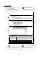
7. SYSTEM CHECKING FROM PERIPHERAL DEVICE MELSEC-Q 7.4 Checking Connect PURPOSE Make sure that the cables between QD75 and servo amplifiers and between servo motors, servo amplifiers and external devices are connected properly. BASIC OPERATION 1. Power on the positioning system and STOP the PLC CPU. 2. Set the connection target. (Refer to Section 7.1.) 3. Choose Checking connect. ¨ Double click Double click 4. Click the "Online" button in the Checking connect window. 5.
7. SYSTEM CHECKING FROM PERIPHERAL DEVICE MELSEC-Q DISPLAY/SETTING SCREEN DISPLAY/SETTING DATA Item Description Operation monitor Indicates the feed present value, feed speed, error No. and warning No. of each axis. JOG speed Set the speed for JOG operation. JOG direction Press the "FWD" or "RVS" button of the axis for JOG operation to start JOG operation. External I/O Indicates the external I/O signal states (ON: Red, OFF: Gray) of the QD75.
7. SYSTEM CHECKING FROM PERIPHERAL DEVICE MELSEC-Q HELPFUL OPERATION (1) Perform the following operation if the I/O logic states of the drive unit ready, upper/lower limit switch and stop signal are different from the initial settings (negative logic). 1. In the extended parameters, set the logic signals in which the following states are established during normal operation. (Refer to Section 8.1.) Drive unit ready, upper limit, lower limit: ON Stop signal: OFF 2. Write the parameters to the QD75.
8. DATA SETTING MELSEC-Q 8. DATA SETTING Set the parameters, positioning data and block start data to be written to the QD75, and check the setting ranges and matching of the data using the simulation or error check function. Write the preset parameters, positioning data and block start data to the QD75 before starting positioning operation. Refer to Section 9.1 for the operation to write the data to the QD75. 8.1 Parameter Setting Set the parameters necessary to exercise positioning control.
8. DATA SETTING MELSEC-Q DISPLAY/SETTING SCREEN Double-click the cell and make setting in the text box or list box. In the text box, you can set the maximum value/minimum value/default value with the right-click menu. When performing operation from the keyboard, enter the value and press the "Enter" key to determine the value. In the list box which shows the set value and set data (example 3:pulse), pressing the "space" key displays a list.
8. DATA SETTING MELSEC-Q 8.2 Positioning Data Setting This section describes the positioning data setting, the addition of circular interpolation control to the positioning data by specifying a sub point, and speed setting using the axis speed calculation function. This section also explains the M code comment setting in which the M codes assigned to the positioning data are annotated with comments. 8.2.
8. DATA SETTING MELSEC-Q DISPLAY/SETTING DATA Item Description No. Indicates the No. of the positioning data. The positioning data that can be ranges from No. 1 to 600. However, No. 1 to 100 are displayed in the initial setting. To change the display range, use the option function (refer to Section 11.5). Pattern Choose the operation pattern for positioning control. The selection range is 0 to 2.
8. DATA SETTING MELSEC-Q Item Description SLV axis Set the interpolation axis when the control method is linear interpolation control (2 axes) or circular interpolation control. Use the SLV axis set dialog box. ACC DEC Choose the ACC time or DEC time from among 0 to 3 and set in the basic parameters 2 and extended parameters 2. Positioning address Set the address for the absolute system or the travel distance for the incremental system.
8. DATA SETTING MELSEC-Q HELPFUL OPERATION (1) When you want to use a smooth arc (curve) on an intersection of two consecutive linear interpolation controls, you can perform the following operation to insert the circular interpolation control positioning data between the linear interpolation controls. Target position Target position Data No. 3 (2-axis linear interpolation control) Data No. 2 (2-axis linear interpolation control) Arc radius Data No.
8. DATA SETTING MELSEC-Q HELPFUL OPERATION (2) Perform the following operation when you want to determine the command speed from the time needed to complete positioning. Use the axis speed calculation function to calculate the command speed from the travel distance, acceleration time, deceleration time, time needed for positioning completion and so on. 1. Open the positioning data edit window of the corresponding axis. (Active status) 2. Click the [Edit] [Speed of axis setting] menu. 3.
8. DATA SETTING MELSEC-Q 8.2.2 M code comment PURPOSE Set comments to M codes which are required for control exercised in synchronization with positioning control. M code comments are data which can be saved only in the personal computer. Up to 50 comments can be set for each axis. BASIC OPERATION 1. Choose the positioning data of the axis to which the M code comments will be set. Double-click. Double-click. 2. Click the [Edit] [M code comment] menu. 3. Set the M code comments. 4.
8. DATA SETTING MELSEC-Q 8.3 Simulation PURPOSE Execute simulation (virtual positioning) with the set positioning data to check the operation of the axis. The axis speed is displayed as locus data for 1-axis control or as locus data for 2axis interpolation control. You cannot perform simulation for 3-/4-axis interpolation control. BASIC OPERATION 1. Open the positioning data edit window. Double-click. Double-click. 2. Click the [Edit] [Simulation] menu. 3. Type the first No.
8. DATA SETTING MELSEC-Q [Locus data for 2-axis interpolation control] DISPLAY/SETTING DATA Item Description Set the first positioning data No. from which simulation starts. Positioning start No. Simulation is performed on the data from the specified No. to the "End" of the operation pattern. Scaling "Fixed ratio" check box Time/Speed (Waveform data) #1 to #4 axis coordinates (Locus data) Used to enlarge or reduce the simulation result in the vertical and horizontal directions.
8. DATA SETTING MELSEC-Q REMARK In the locus data for circular interpolation control, lines may be broken due to a data processing error during drawing. HELPFUL OPERATION When you want to try the command speeds (waveform) or addresses (locus) at the setting of the positioning data, you can set or change the positioning data while simultaneously checking the simulation result.
8. DATA SETTING MELSEC-Q 8.4 Block Start Data Setting Set the block start data for controlling a positioning start and the condition data used as a condition for a special start. • The block start data is equivalent to the start block data of the AD75. 8.4.1 Block start data PURPOSE Specify the positioning data No. as a point, and set the block start data which sets the starting condition, execution order and execution count to each point. You can set up to 50 points per block. There are blocks No.
8. DATA SETTING MELSEC-Q DISPLAY/SETTING DATA Item Point No. Pattern Data No. Description Shows the point numbers 1 to 50. Select whether positioning control is ended at the point where positioning was completed or positioning control will be continued to the next point. Set the positioning data No. specified at the point. The setting range is positioning data No. 1 to 600. Choose the type of positioning control start per point. The selection range is 0 to 6.
8. DATA SETTING MELSEC-Q 8.4.2 Condition data PURPOSE Set the condition data which will be the starting conditions of the conditional start, wait start, simultaneous start and FOR condition in the block start data. BASIC OPERATION 1. Choose the block start data of the axis to which the condition data will be set. Double-click. Double-click. 2. Click the [Edit] [Condition data edit] menu. 3. Choose the data No. to be set in the Condition data list dialog box. 4.
8. DATA SETTING MELSEC-Q DISPLAY/SETTING DATA Item Description No. Shows the condition data No. Condition data Shows the condition data set in the Condition data edit dialog box. "Edit" button Click this button to display the Condition data edit dialog box. "Delete" button Click this button to delete the condition data at the cursor. Choose the type of the condition operator of the condition data.
8. DATA SETTING MELSEC-Q 8.5 Error Check PURPOSE Make error check to check the parameter settings, positioning data and block start data for mismatches and setting omissions. For the error check range, refer to QD75 User's Manual. BASIC OPERATION 1. Set the error-checked project as the active project on the project tree view. (Refer to Section 5.2.) 2. Click the [Tool] [Error check] menu.
9. QD75 DATA WRITE/READ/VERIFY MELSEC-Q 9. QD75 DATA WRITE/READ/VERIFY Perform write to QD75/read from QD75/verify QD75 data, data write from QD75 buffer memory to flash ROM, and QD75 initialization. QD75 Buffer memory Via QCPU, Q corresponding serial communication module or Q corresponding MELSECNET/H network remote I/O module :Only when connecting to the remote I/O module directry.
9.
9. QD75 DATA WRITE/READ/VERIFY MELSEC-Q [Verify result dialog box] DISPLAY/SETTING DATA Item Description Positioning data Set the data used for write to QD75/read from QD75/verify QD75 data from positioning data, Block start data block start data and parameters. Parameter Block start data includes condition data. "Flash-ROM write" check When performing write to QD75, set a request to write from buffer memory to flash ROM at box the same time.
9. QD75 DATA WRITE/READ/VERIFY MELSEC-Q 9.2 Flash ROM write request PURPOSE Issue the command to write the QD75 buffer memory data to the flash ROM. Write from buffer memory to flash ROM is batch-performed in the full ranges of the parameters, positioning data and block start data (including condition data). • Whether the flash ROM request may be performed or not is determined by the PLC state check setting in Option setting. (Refer to Section 11.5) BASIC OPERATION 1. Place the QCPU in the STOP status.
10. POSITIONING DEBUGGING MELSEC-Q 10. POSITIONING DEBUGGING Debug positioning operation by checking the parameters, positioning data and other data set to the QD75 for errors, monitoring the positioning operation, and performing various operation tests by positioning data test operation and JOG operation. • All axes stop if a communications error occurs, e.g. SW D5C-QD75P-E is forced to end, the peripheral device is powered off, or the connection cable is disconnected, in the test mode.
10. POSITIONING DEBUGGING MELSEC-Q 10.1 QD75 Error Check PURPOSE Make an error check on the parameters, positioning data and block start data stored in the buffer memory of the specified QD75. Refer to QD75 User’s Manual, for the action taken for the check results. BASIC OPERATION 1. Choose the [Online] [Error check QD75 data] menu ( ). 2. Clicking the corresponding QD75 in the System monitor dialog box shows the QD75 Error check dialog box. Refer to Error Check (Section 8.
10. POSITIONING DEBUGGING MELSEC-Q 10.2 Monitor Monitor the positioning data and block start data execution states on an axis by axis basis, or perform detailed monitor of the error histories, signal states, present values, speeds, etc. on a project basis. 10.2.1 Monitoring the positioning data/block start data PURPOSE From the positioning data/block start data edit window of any axis, monitor the positioning data No.s or block No.s and point No.s being executed. BASIC OPERATION 1.
10. POSITIONING DEBUGGING MELSEC-Q 10.2.2 Operation monitor PURPOSE Monitor the feed present value, axis feed speed, axis status, positioning data No. executed last, error/warning code occurring currently, and M code of each axis. This monitor is used to confirm the basic axis states. BASIC OPERATION 1. Choose Operation monitor. Double-click. Double-click. 2. Click the "Monitor start" button. 3. To exit, click the "Monitor stop" button.1. Choose Operation monitor.
10. POSITIONING DEBUGGING MELSEC-Q DISPLAY/SETTING DATA Item Title bar Feed present value Axis speed Axis status Description Shows the project name and I/O address. Indicates the feed present value. Buffer memory address (Axis #1): 800, 801 Indicates the feed speed. Buffer memory address (Axis #1): 812, 813 Indicates the axis status. Buffer memory address (Axis #1): 809 Indicates the positioning data No. in execution. No. Note that if other than the positioning data No.
10. POSITIONING DEBUGGING MELSEC-Q 10.2.3 History monitor PURPOSE Monitor the error, warning and start histories stored in the QD75 buffer memory during operation monitor. BASIC OPERATION 1. Perform the basic operation in Section 10.2.2 to display the operation monitor window. 2. Click the "History" button on the operation monitor window. 3. Click the <>/<>/<> tab.
10. POSITIONING DEBUGGING MELSEC-Q DISPLAY/SETTING SCREEN [Start history monitor] DISPLAY/SETTING DATA Item Title bar No. Axis Description Shows the I/O address of the QD75 being monitored. Represents the order of starts since power-on. If there are more than 16 starts, the older ones are deleted. Indicates the axis started. Buffer memory address: 1212 Indicates the start command destination. Start The command destination is the PLC CPU, peripheral device or external signal.
10. POSITIONING DEBUGGING MELSEC-Q 10.2.4 Signal monitor PURPOSE Monitor the I/O signals (X/Y device), external I/O signals and status signals of the QD75. For the signals, refer to QD75 User’s Manual. BASIC OPERATION 1. Perform the basic operation in Section 10.2.2 to display the operation monitor window. 2. Click the "Signal" button in the operation monitor window. 3. Click the <>/<>/<>/<> tab.
10. POSITIONING DEBUGGING MELSEC-Q DISPLAY/SETTING SCREEN [External I/O signal monitor] DISPLAY/SETTING DATA Item Title bar External I/O signal Description Shows the I/O address of the QD75 being monitored. Shows the On/Off states of the external I/O signals of the QD75. Buffer memory address (Axis #1): 816 Shows whether the start, V/P switch and P/V switch commands given by the external start External REQ enabled signals are valid ( ) or invalid ( ).
10. POSITIONING DEBUGGING MELSEC-Q DISPLAY/SETTING SCREEN [Status signal monitor] DISPLAY/SETTING DATA Item Title bar Status signal Description Shows the I/O address of the QD75 being monitored. Shows the On/Off states of the status signals of the QD75.
10. POSITIONING DEBUGGING MELSEC-Q 10.2.5 Axis operation monitor PURPOSE Monitor the settings, states and others of the axis control data, velocity/position control, position/velocity control, original point return and JOG/MPG operation during operation monitor. With operation monitor, you can check the detailed states of operation and the QD75 settings made with the sequence program or peripheral device. For each monitor item, refer to QD75 User's Manual. BASIC OPERATION 1.
10. POSITIONING DEBUGGING MELSEC-Q DISPLAY/SETTING DATA Item Title bar Description Shows the I/O address of the QD75 being monitored. Shows the destination for positioning control. For velocity/position switching control or position/velocity switching control, "0" is displayed Target value for velocity control and the destination appears for position control. "0" is shown for other operations.
10. POSITIONING DEBUGGING MELSEC-Q DISPLAY/SETTING SCREEN [Position/velocity control monitor] (Screen example shows Operation monitor.) DISPLAY/SETTING DATA Item Description Indicates the target speed for positioning data, OPR or JOG operation. Target speed For interpolation control, the composite speed or reference axis speed is displayed for the reference axis and 0 appears for the interpolation axis.
10. POSITIONING DEBUGGING MELSEC-Q DISPLAY/SETTING SCREEN [Position/velocity control monitor] (Screen example shows Operation monitor.) DISPLAY/SETTING DATA Item Description Indicates the target speed for positioning data, OPR or JOG operation. Target speed For interpolation control, the composite speed or reference axis speed is displayed for the reference axis and 0 appears for the interpolation axis.
10. POSITIONING DEBUGGING MELSEC-Q DISPLAY/SETTING SCREEN [OPR monitor] (Screen example shows Operation monitor.
10. POSITIONING DEBUGGING MELSEC-Q DISPLAY/SETTING SCREEN [JOG/MPG monitor] (Screen example shows Operation monitor.) DISPLAY/SETTING DATA Item FWD JOG RVS JOG JOG speed JOG speed limit value Description Indicates the direction during JOG operation in the sequence program. Indicates the axis speed during JOG operation in the sequence program. Buffer memory address (Axis #1): 1518, 1519 Indicates the JOG operation limit value set in the extended parameters 2.
10. POSITIONING DEBUGGING MELSEC-Q 10.3 Sampling Monitor Monitor the ON/OFF of any registered signals and the buffer memory values while simultaneously sampling them. 10.3.1 Sampling signal monitor PURPOSE You can monitor the ON/OFF of the specified X/Y devices, external I/O signals and status signals in the timing chart. BASIC OPERATION 1. Choose Sampling monitor (signal). Double-click. Double-click. 2. Click the "Setup" button in the Sampling monitor (signal) window. 3.
10. POSITIONING DEBUGGING MELSEC-Q [Sampling monitor dialog box] DISPLAY/SETTING DATA Item "Setup" button Sampling monitor result Sampling interval Signal Select Signal item "OK" button Description Click this button to display the Sampling monitor dialog box. ON/OFF states are shown in the HIGH/LOW timing chart. The sampling cycle time changes with the sampling interval. The timing chart is enlarged or reduced according to the screen size.
10. POSITIONING DEBUGGING MELSEC-Q 10.3.2 Sampling buffer monitor PURPOSE You can monitor the buffer memory storage values of the specified QD75 as waveform data. BASIC OPERATION 1. Choose Sampling monitor (Buffer). Double-click. Double-click. 2. Click the "Setup" button in the Sampling monitor (Buffer) window. 3. Set the buffer memory addresses, upper limit value and lower limit value in the Sampling Buffer area data setting dialog box. ). 4. Click the [Online] [Monitor] [Monitor On/Off] menu ( 5.
10. POSITIONING DEBUGGING MELSEC-Q [Sampling Buffer area data setting dialog box] DISPLAY/SETTING DATA Item "Setup" button Sampling monitor result Sampling interval Buffer area data Upper Limit Lower Limit "OK" button Description Click this button to display the Sampling Buffer area data setting dialog box. Shows the buffer memory values as waveform data. The sampling cycle time changes with the sampling interval. The waveform data are enlarged or reduced according to the screen size.
10. POSITIONING DEBUGGING MELSEC-Q 10.4 Test Place the QD75 in the test mode during operation monitor, and test the positioning start, present value change, speed change, OPR, JOG or MPG operation. Each operation can be tested in the cableless test mode using just the QD75. ! CAUTION Before performing the OPR, JOG operation, positioning data or other test in the test mode, read the manual carefully, fully ensure safety, and set the PLC CPU to STOP.
10. POSITIONING DEBUGGING MELSEC-Q HELPFUL OPERATION Perform the following operation when you want to test the positioning data or block start data before installing external equipment such as the servo amplifiers and motors. 1. Click the [Online] [Test] [Cableless mode] menu. 2. Choose the test mode by performing the above operation. 3. The operation that will follow is the same as in the corresponding test. Refer to the corresponding pages. 4.
10. POSITIONING DEBUGGING MELSEC-Q DISPLAY/SETTING SCREEN DISPLAY/SETTING DATA Item Monitor Start mode Description Shows the axis status. Choose the start mode of test operation. • Positioning start Test operation is started from the specified positioning data No. • Block start Test operation is started from the specified block point No. • Multiple axis sync start data No. Test operation is started from the positioning data No. specified per axis. Set the positioning data No.
10. POSITIONING DEBUGGING Item MELSEC-Q Description When performing a step start, click the unchecked step start check box. When you made it valid, choose the step start type. • Data No. units Independently of the operation pattern, operation is started from the specified positioning data No., and is performed and brought to a step standby status per data.
10. POSITIONING DEBUGGING MELSEC-Q 10.4.2 Present value change test PURPOSE Change the feed present value of the QD75 to the specified address. BASIC OPERATION 1. Place the QD75 in the test mode in accordance with Section 10.4 (1). 2. Click the [Online] [Test] [Operation test] [Operation test #1 to #4] menu ( ). to 3. Click the <> tab in the TEST MODE setting dialog box. 4. Type a new value in the text box and click the "Present-value change" button. 5.
10. POSITIONING DEBUGGING MELSEC-Q 10.4.3 Speed change test PURPOSE Make a speed and/or acceleration/deceleration time change to the axis operating in the positioning start, OPR or JOG operation test to check the adequate speed and/or acceleration/deceleration time. BASIC OPERATION 1. Place the QD75 in the test mode in accordance with Section 10.4 (1). 2. Click the [Online] [Test] [Operation test] [Operation test #1 to #4] menu ( ). to 3. Perform positioning start test (refer to Section 10.4.
10. POSITIONING DEBUGGING MELSEC-Q DISPLAY/SETTING DATA Item Monitor Speed change "REQ. speed change" button Speed override "REQ. speed override" button "ACC/DEC time set enable" check box Acceleration time Deceleration time "All axis stop" button "Stop" button <> tab <> tab <> tab <> tab Description Shows the axis status. Set a new speed to replace the command speed, OPR speed or JOG operation speed of the running axis.
10. POSITIONING DEBUGGING MELSEC-Q 10.4.4 OPR test PURPOSE Perform an OPR test to set up an original point and correct the preset OPR basic parameters and OPR extended parameters. BASIC OPERATION 1. Place the QD75 in the test mode in accordance with Section 10.4 (1). 2. Click the [Online] [Test] [Operation test] [Operation test #1 to #4] menu ( to ). 3. Click the <> tab in the TEST MODE setting dialog box. 4. Check the OPR method, OPR speed and Original point address. 5.
10. POSITIONING DEBUGGING MELSEC-Q DISPLAY/SETTING DATA Item Monitor OPR type "REQ. OPR" button OPR method OPR speed Original point address "All axis stop" button "Stop" button <> tab <> tab <> tab <> tab Description Shows the axis status. Chose the type of a starting method used in the OPR test. • Machine OPR OPR is performed using the dog or zero phase signal depending on the OPR method. Performed when the original point is set up.
10. POSITIONING DEBUGGING MELSEC-Q 10.4.5 JOG/MPG operation test PURPOSE When debugging positioning control by JOG or MPG operation, you can conduct the following tests.
10. POSITIONING DEBUGGING MELSEC-Q DISPLAY/SETTING DATA Item Description Shows the axis status. Set the speed for JOG operation. JOG speed You cannot set any value beyond the JOG speed limit. JOG speed is ignored for inching operation. Set the travel amount for inching operation. Inching value Set "0" for JOG operation. Set the mouse pointer to the required arrow and press the left button of the mouse or press the space key to start JOG operation.
10.
11. USEFUL FUNCTIONS MELSEC-Q 11. USEFUL FUNCTIONS 11 Out of the functions that can be performed on SW D5C-QD75P-E, this chapter describes the functions and operations useful for project execution, positioning data setting, etc. and the functions which support settings.
11. USEFUL FUNCTIONS MELSEC-Q [Verify project dialog box (2)] [Verify result dialog box] DISPLAY/SETTING DATA Item Project name Project save path "Reference" button "Verify" button Verify project dialog box (2) Verify result dialog box Description Click the project name of the verify destination. Shows the project save path of the verify destination. Click this button to display the Project tree dialog box (refer to Section 6.1). Click this button to show the Verify project dialog box (2).
11. USEFUL FUNCTIONS MELSEC-Q 11.1.2 Changing the QD75 model after data setting PURPOSE Change the QD75 model after setting the parameters, positioning data or other data. If you choose "New QD75 read" in New Project, the model is the same as the QD75 at the read destination. Therefore, when utilizing the data for the other model, change the QD75 model after completion of read. BASIC OPERATION 1. Set the required project as the active project. (Refer to Section 5.2.
11. USEFUL FUNCTIONS MELSEC-Q 11.1.3 Intelligent function utility PURPOSE Make setting to read the following data automatically from the QD75 buffer memory to the QCPU devices (e.g. data registers). The set data are stored in the intelligent function module parameters of the GPPW project. • Feed present value • Machine feed value • Feed speed • Error No. • Warning No.
11. USEFUL FUNCTIONS MELSEC-Q [Intelligent function module utility] DISPLAY/SETTING DATA Item Project save path GPPW project Start I/O No. Package name Module model name Intelligent function module parameter setting module "Auto refresh" button "Delete" button PLC side device "Make text file" button "End setup" button Description Choose the save destination of the GPPW project to which automatic refresh setting will be made. Choose the GPPW project to which automatic refresh setting will be made.
11. USEFUL FUNCTIONS MELSEC-Q 11.1.4 Multi-module batch write PURPOSE Batch write to multiple QD75s. • Whether multi-module batch write may be performed or not is determined by the PLC state check setting in Option setting. (Refer to Section 11.5) BASIC OPERATION 1. Open all projects to be batch written. 2. Specify the connection target in each project. (Refer to Section 7.1.) 3. Click the [Online] [Writing of batch of multi-module] menu. 4.
11. USEFUL FUNCTIONS MELSEC-Q DISPLAY/SETTING DATA Item Project list Write project list ">>Selected" button "<
11. USEFUL FUNCTIONS MELSEC-Q 11.2 Edit Functions for Data Setting This section explains the edit functions which can be used for positioning data or block start data setting. 11.2.1 Cut/copy/paste These functions cut/copy and paste some part of the positioning or block start data settings. Also these functions cut/copy the values entered in Microsoft Excel or Word table and pastes them to the positioning data or block start data of SW D5C-QD75P-E. R R R (1) Cut Used to cut the selected range.
11. USEFUL FUNCTIONS MELSEC-Q (3) Paste Used to paste the cut or copied data to the selected range. Note that paste may not be made if: • The control method is not set to the data of paste destination; • The data of cut or copy destination is different in control method from the data of paste destination; or • The item cut or copied is different from the item of paste destination. 1) Choose the paste destination (copy destination) of the data cut (copied). 2) Click the [Edit] [Paste] menu ( ).
11. USEFUL FUNCTIONS MELSEC-Q HELPFUL OPERATION (1) When making the same setting for multiple positioning data or block start data, perform the following operation to make batch setting in the selected range. Note that batch setting may be made for the same item (column) only. It cannot be made if you selected multiple items (columns). 1) Choose the batch setting range. Example: Batch-set the control method of positioning data No. 1 to 5.
11. USEFUL FUNCTIONS MELSEC-Q HELPFUL OPERATION (2) Perform the following operation to cut/copy and paste all ranges of the positioning data or block start data displayed. 1. Click the [Edit] [Select all] menu. [Result of clicking [Select all] in the positioning data edit window] • When "data No. 1 to data No. 100" has been selected in the data No. setting of the SW D5C-QD75P-E option function, positioning data No. 101 to No. 600 are not included in the selection range.
11. USEFUL FUNCTIONS MELSEC-Q 11.2.2 Jump PURPOSE Move the cursor to the data No. specified for a positioning data edit window. Alternatively, move the cursor to the point No. specified in the block start data edit window. BASIC OPERATION 1. Click the [Edit] [Jump] menu. 2. Set the positioning data No. or block start data point No. of the jump destination in the JUMP dialog box. 3. Click the "OK" button.
11. USEFUL FUNCTIONS MELSEC-Q 11.2.3 Clearing the rows/columns PURPOSE Clear only the rows or columns selected in the positioning data window or block start data edit window. BASIC OPERATION 1. Choose the rows (columns) which you want to initialize in the positioning data or block start data edit window. 2. Click the [Edit] [Clear row]/[Clear column] menu. Alternatively, click the [Clear row]/[Clear column] menu in the right-click menu.
11. USEFUL FUNCTIONS MELSEC-Q 11.2.4 Initializing the data PURPOSE Initialize the parameters, positioning data and block start data (including condition data) of the active project axis-by-axis. Note that the project data saved in the QD75, HD and FD are not initialized. BASIC OPERATION 1. Set the project to be initialized as the active project. (Refer to Section 5.2.) 2. Click the [Tool] [Initialize data] menu. 3. Set the types and axes of the data to be initialized in the Data initialize dialog box.
11. USEFUL FUNCTIONS MELSEC-Q 11.3 Copying the Data Copy the positioning data, block start data and parameters set to the project axis-byaxis. Also, copy the set block start data to another block. When copying data to another project, use copy/paste of the edit function. (Refer to Section 11.2.1.) 11.3.1 Copying the data on an axis basis (Axis copy) PURPOSE Using the axis copy function, copy the positioning data, block start data and parameters of any axis to another axis of the same project.
11. USEFUL FUNCTIONS MELSEC-Q 11.3.2 Block start copy PURPOSE Using the block start copy function, copy the block start data to the other blocks. The block start copy function is performed to copy data between blocks in the same project. BASIC OPERATION 1. Display the block start data edit window (refer to Section 8.4). 2. Click the [Edit] [Block start copy] menu. 3. Set the block No. of the copy source and the block No. of the copy destination. 4. Click the "OK" button.
11. USEFUL FUNCTIONS MELSEC-Q 11.4 Navigation Function PURPOSE Perform the operations necessary to use the QD75, from setting of the parameters and positioning data to write to QD75, monitor and test in the wizard format. For parameter setting data, refer to QD75 User’s Manual. BASIC OPERATION 1. Set the connection target. (Refer to Section 7.1.) 2. Click the [Tool] [Navigation] menu. 3. When the Navigation function screen appears, perform operation using the following procedure.
11. USEFUL FUNCTIONS MELSEC-Q (From the preceding page) 4) Choose the axis in Change axis and set the positioning data. After setting, click the "Next>>" button. 5) Set I/O adress To write data to the flash ROM of the QD75 at the same time, click unchecked "Write to flash ROM". 6) Click the "Write to QD75" button. When write is completed, click the "Next>>" button. 7) Click the "Monitor start" button. 8) Click the "Test start" button.
11. USEFUL FUNCTIONS MELSEC-Q (From the preceding page) 9) Set the positioning data No. in Start and click the "Start" button to start test operation. Use the "Stop", "Error reset" and/or "M code OFF" button as necessary. 10) When the test is over, click the "Test stop" button. After exiting from the test mode, click the "Next>>" button. 11) When saving the set parameters and positioning data, click the "Save as project" button. When not saving them, click the "End" button.
11. USEFUL FUNCTIONS MELSEC-Q 11.5 Option Setting PURPOSE Set the option function of SW D5C-QD75P-E. The option function is used to make settings for write to QD75 and set the display range of positioning data. BASIC OPERATION 1. Click the [Tool] [Option] menu. 2. Make settings in the Option settings dialog box. 3. To exit, click the "OK" button.
11. USEFUL FUNCTIONS MELSEC-Q DISPLAY/SETTING DATA Item Flash ROM write Write data enable flag Positioning data set Description Select whether data will be written to flash ROM or not in the initial setting for write to QD75. • YES ......Choose Yes to make the initial setting that data will be written to flash ROM when write to QD75 is performed. • NO ........Choose No to make the initial setting that data will not be written to flash ROM when write to QD75 is performed.
11. USEFUL FUNCTIONS MELSEC-Q 11.6 Printing the Project Data Print the positioning data, block start data and parameters set in the project. 11.6.1 Printer setting PURPOSE Choose the printer connected to the peripheral device, paper and printing orientation. For printer setting, refer to Microsoft Windows Operating System manual. Also, for the printer properties, refer to the printer manual as they depend on Microsoft Windows Operating System manual printer driver used. R R R R BASIC OPERATION 1.
11. USEFUL FUNCTIONS MELSEC-Q 11.6.2 Printing PURPOSE Print the positioning data, block start data (including condition data) and parameter data of the active project. BASIC OPERATION 1. Set the project to be printed as the active project. (Refer to Section 5.2.) 2. Click the [Project] [Print] menu ( ). 3. Set the axes and data types and ranges to be printed. 4. Click the "Print preview" button. 5. Clicking the "Print" button shows the Print dialog box. 6.
11. USEFUL FUNCTIONS MELSEC-Q [Print preview screen] [Print dialog box] DISPLAY/SETTING DATA Item Print project Axis specification Print data Positioning data No. Block start data No. Parameter data "Printer setting" button "Print" button "Print preview" button "Next Page" button "Prev Page" button "One Page/Two Page" button "Zoom In" button "Zoom Out" button Printer Name "Properties" button Print range Copies "OK" button Description Shows the project name to be printed.
11.
11. USEFUL FUNCTIONS MELSEC-Q 11.7 Positioning Data Setting in Test Mode In the test mode, import the feed address to the positioning data address and write changed positioning data to the QD75. 11.7.1 Teaching PURPOSE Enter the feed address of the axis moved by JOG or MPG operation into the address of the positioning data. BASIC OPERATION 1. Click unchecked Write data enable flag in Option. (Refer to Section 11.5.) ). 2. Click the [Online] [Test] [Test On/Off] menu ( 3.
11. USEFUL FUNCTIONS MELSEC-Q DISPLAY/SETTING SCREEN DISPLAY/SETTING DATA Item Description Feed Address Shows the feed address of the QD75. "Update" button Click this button to update the "feed address" to the latest feed address. "Teaching" button Click this button to enter the "feed address" into the cell selected in the positioning data edit window. Positioning data edit Screen used to perform teaching or positioning data test edit in the test mode.
11. USEFUL FUNCTIONS MELSEC-Q 11.7.2 Positioning data test edit PURPOSE Change the positioning data or block start data in the test mode and write them to the QD75. BASIC OPERATION 1. Click unchecked Write data enable flag in Option. (Refer to Section 11.5.) 2. Click the [Online] [Test] [Test On/Off] menu ( ). 3. The positioning data/block start data edit window appears. (Refer to Section 8.2.1/Section 8.4.1.) 4. Click the [Online] [Test] [Edit positioning data] menu ( ). 5.
11. USEFUL FUNCTIONS MELSEC-Q 11.8 Wave Trace Using the wave trace function in the trace mode, show the speed command (axis speed) for positioning operation as waveform data. 11.8.1 Wave trace condition setting PURPOSE To execute the wave trace, set the trace starting condition and the data to be traced. BASIC OPERATION 1. Choose Wave trace. Double-click. Double-click. 2. Click the "Setting" button in the wave trace window. 3.
11. USEFUL FUNCTIONS MELSEC-Q DISPLAY/SETTING DATA Item Trace interval Description Set the trace interval within the range 1 to 256. 1.77ms. The interval is the set value Choose the actual trace starting condition. • No condition Trace trigger Trace starts at the start request of the peripheral device. • Wait start Trace actually starts when the start signal (X10/X11/X12/X13) turns on after the start request from the peripheral device. Choose the trace stopping condition.
11. USEFUL FUNCTIONS MELSEC-Q 11.8.2 Wave trace execution PURPOSE Execute wave trace after setting the trace conditions in accordance with Section 11.8.1. BASIC OPERATION 1. Perform the basic operation in Section 11.8.1 to set the trace conditions. 2. Click the "Trace" button to initialize the QD75. 3. When initialization is completed, click the "Start" button in the dialog box. 4. The trace data is read when the trace stop type condition is satisfied or the "Stop" button is clicked. 5.
11. USEFUL FUNCTIONS MELSEC-Q DISPLAY/SETTING DATA Item Max Min Time Description Show the maximum and minimum values during tracing of each data. Shows the tracing time. Shows the trace results. Waveform data The horizontal axis indicates time. The vertical axis represents the value of the traced data. Use the scroll bars to move the display position. Horizontal Vertical Preserve aspect Trace data Show the display multiplying factor of the locus data.
11. USEFUL FUNCTIONS MELSEC-Q 11.9 Locus Trace Using the locus trace function in the trace mode, show 2-axis interpolation control or simultaneous start (2 axes) as locus data. 11.9.1 Locus trace condition setting PURPOSE To execute the locus trace, set the trace starting condition and the data to be traced. BASIC OPERATION 1. Choose Locus trace. Double-click. Double-click. 2. Click the "Setting" button in the locus trace window. 3.
11. USEFUL FUNCTIONS MELSEC-Q DISPLAY/SETTING DATA Item Description Choose the actual trace starting condition. • No condition Trace trigger Trace starts at the start request of the peripheral device. • Wait start Trace actually starts when the start signal (X10/X11/X12/X13) turns on after the start request from the peripheral device. Choose the trace stopping condition. • Buffer full Trace stops when the trace data area becomes full.
11. USEFUL FUNCTIONS MELSEC-Q 11.9.2 Locus trace execution PURPOSE Execute locus trace after setting the trace conditions in accordance with Section 11.9.1. BASIC OPERATION 1. Perform the basic operation in Section 11.9.1 to set the trace conditions. 2. Click the "Trace" button to initialize the QD75. 3. When initialization is completed, click the "Start" button in the dialog box. 4. The trace data is read when the trace stop type condition is satisfied or the "Stop" button is clicked. 5.
11. USEFUL FUNCTIONS MELSEC-Q DISPLAY/SETTING DATA Item Max Min Time Description Show the maximum and minimum values during tracing of each data. Shows the tracing time. Shows the trace results. The horizontal and vertical axes indicate the respective addresses (travel distances) of the Locus data axis numbers set in trace condition setting. (When #1-#2 is selected as the axis number to be traced, the horizontal axis is Axis #1 and the vertical axis is Axis #2.
11. USEFUL FUNCTIONS MELSEC-Q 11.10 Help PURPOSE With the help function, you can check the following. • Error code List • Warning code List • I/O signals • Buffer memory address List BASIC OPERATION 1. Click the [Help] [Error/Warning/List of Buffer memory] menu.
11.
APPENDIX MELSEC-Q APPENDIX APPENDIX 1 QD75 READ/WRITE REFERENCE PROCESSING TIMES The following table indicates the reference times required for read/write processing from SW D5C-QD75P-E to QD75. Read/write should be performed in the following environment. Item Description CPU Peripheral device Read/write data Pentium R 166MHz, Microsoft R WindowsNT R Workstation 4.
APPENDIX MELSEC-Q MEMO Appendix - 2
INDEX [2] comment M code.........................................................8- 8 positioning data ...........................................8- 5 condition of special start ...........................................8- 13 of trace start........................................11-31, 35 condition data..........................................8- 13, 14 connection setup.............................................7- 1 copy of block start data.....................................11-16 of selection range..
resetting of ....................................7- 6, 8, 10- 1 existing opening project ........................................... 6- 5 utilizing data................................................ 6- 9 [K] keyboard operation block start data edit by ...............................8-12 focus movement by.....................................5- 4 for dialog box...............................................5- 3 for project tree view.....................................5- 2 parameter edit by ...............
of buffer memory ..................................... 10-19 of external I/O signals............................... 10- 9 of JOG operation ..................................... 10-16 of MPG operation .................................... 10-16 of positioning data in execution................ 10- 3 of status signal......................................... 10-10 of X/Y device............................................. 10- 8 On/Off .......................................
of printer ...................................................11-22 of selection range in batch.......................11-10 option ........................................................11-20 shortcut key.....................................................5- 4 signal monitor................................................10- 8 single-module test........................................10-21 software registration card ...............................4- 3 specifying access target .............................
test without external device......................... 10-21 text box ........................................................... 5- 3 time-out........................................................... 7- 2 title bar ............................................................ 5- 1 toolbar ............................................................. 5- 1 trace displaying the results of..................... 11-33, 35 setting the conditions of..................... 11-29, 33 trace data file read of ..........
Microsoft, Windows and Microsoft Windows NT are registered trademarks of Microsoft Corporation in the United States and other countries. Pentium is either a trademark or registered trademark of Intel Corporation in the United States and other countries. Other company and product names herein may be either trademarks or registered trademarks of their respective owners.
Positioning Module Software Package Operating Manual MODEL SW0D5C-QD75P-O-E MODEL CODE 13J973 SH(NA)-080057-C(0010)MEE HEAD OFFICE : MITSUBISHI DENKI BLDG MARUNOUCHI TOKYO 100-8310 TELEX : J24532 CABLE MELCO TOKYO NAGOYA WORKS : 1-14 , YADA-MINAMI 5 , HIGASHI-KU, NAGOYA , JAPAN When exported from Japan, this manual does not require application to the Ministry of International Trade and Industry for service transaction permission. Specifications subject to change without notice.