Type QD75P/QD75D Positioning Module User’s Manual (Hardware) QD75P1, QD75D1 QD75P2, QD75D2 QD75P4, QD75D4 Thank you for buying the Mitsubishi general-purpose programmable controller MELSEC-Q Series Prior to use, please read both this manual and detailed manual thoroughly and familiarize yourself with the product.
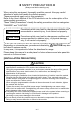
z SAFETY PRECAUTIONS z (Always read before starting use) When using this equipment, thoroughly read this manual. Also pay careful attention to safety and handle the module properly. These precautions apply only to this equipment. Refer to the User’s Manual of the CPU module to use for a description of the system safety precautions. These "Safety Precautions" classify the safety precautions into two categories: "DANGER" and "CAUTION".
[WIRING PRECAUTION] DANGER z Completely turn off the externally supplied power used in the system when installing or placing wiring. Not doing so may cause electric shock or damage to the product. CAUTION z Check the layout of the terminals and then properly route the wires to the module. z Solder connectors for external device properly. Insufficient soldering may cause malfunction. z Be careful not to let foreign matter such as sawdust or wire chips get inside the module.
Revisions Print Date Oct., 1999 Feb., 2000 * The manual number is noted at the lower left of the back cover. *Manual Number Revision IB(NA)-0800063-A First edition IB(NA)-0800063-B Addition "Confirmation to EMC directive" Jun., 2001 IB(NA)-0800063-C Modification About Manuals, Conformation to the EMC Directive and Low Voltage Instruction, Chapter 2, Chapter 4, Chapter 5 Nov., 2001 IB(NA)-0800063-D Addition Chapter 1, Chapter 2, Chapter 4, Section 5.2, Section 5.3, Chapter6 Jul.
CONTENTS 1. Overview ........................................................................................................1 2. Performance Specifications ...........................................................................2 3. Handling.........................................................................................................3 3.1 Handling Precautions................................................................................3 4. Part Identification Nomenclature ..................
1. Overview This manual explains how to handle the Positioning Module, model numbers QD75P1, QD75P2, QD75P4, QD75D1, QD75D2 and QD75D4 (hereinafter collectively referred to as the QD75). After unpacking the QD75, please verify that the corresponding product as listed below is enclosed in the package.
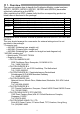
2. Performance Specifications (1) The performance specifications for the QD75P1, QD75P2 and QD75P4 Item Number of axes Maximum output pulse count Maximum connection distance between servos Applicable wire size Applicable connector Number of I/O occupied points 5 V DC current consumption Flash ROM write count Weight Specification QD75P2 2 axes QD75P1 1 axis QD75P4 4 axes 200 kpulse/s 2m (6.56ft) 0.
3. Handling CAUTION z Use the programmable controller in an environment that meets the general specifications contained in CPU module User's Manual to use. Using this programmable controller in an environment outside the range of the general specifications may cause electric shock, fire, malfunction, and damage to or deterioration of the product. z While pressing the installation lever located at the bottom of module, insert the module fixing tab into the fixing hole in the base unit until it stops.
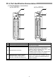
4. Part Identification Nomenclature (1) Part identification nomenclature (a) For QD75P4 (b) For QD75D4 1) 1) 2) 2) 3) 3) 5) 5) 4) No. Name 1) 2) RUN indicator LED, ERR indicator LED Axis display LED (AX1 to AX4) 3) External device connector 4) Differential driver common terminal (Differential driver output system (QD75D1, QD75D2, QD75D4) only) 5) Serial number plate Details Refer to the next page.
(2) LED display contents Details of indication RUN QD75 4 RUN ERR. AX1 AX2 AX3 AX4 ERR. RUN ERR. RUN ERR. RUN ERR. RUN ERR. RUN ERR. RUN ERR. AX1 AX2 AX3 AX4 AX1 AX2 AX3 AX4 AX1 AX2 AX3 AX4 AX1 AX2 AX3 AX4 AX1 AX2 AX3 AX4 AX1 AX2 AX3 AX4 AX1 AX2 AX3 AX4 Points to be confirmed Extinguishment of RUN LED Error Lighting of RUN LED, Extinguishment of ERR. LED The hardware is faulty or watch dog timer error occurs. The module is normal. Lighting of ERR.
(3) External device connector signal layout Pin layout B20 B19 B18 B17 B16 B15 B14 B13 B12 B11 B10 B9 B8 B7 B6 B5 B4 B3 B2 B1 A20 A19 A18 A17 A16 A15 A14 A13 A12 A11 A10 A9 A8 A7 A6 A5 A4 A3 A2 A1 Axis 4 (AX4) Pin Signal name No.
5. Wiring DANGER z Completely turn off the externally supplied power used in the system when installing or placing wiring. Not doing so may cause electric shock or damage to the product. 5.1 Wiring Precautions (1) Always confirm the terminal layout before connecting the wires to the QD75. (2) Correctly solder the external wiring connector. An incomplete soldering could lead to malfunctioning. (3) Make sure that foreign matter such as cutting chips and wire scraps does not enter the QD75.
(9) If cables to connect to QD75 absolutely must be positioned near (within 100 mm) the power line, use a general shielded cable. The shield must be grounded on the QD75 side. Connector Connector (A6CON1/A6CON2) Shielded cable To external devices To external device To drive unit To QD75 Use the shortest possible length to ground the 2mm2 or more FG wire. (The shield must be grounded on the QD75 side.) The length between the connector and the shielded cables should be the shortest possible.
Wrap the coated parts with a heat contractile tube. (10) To make this product conform to the EMC directive and low voltage instruction, be sure to use the AD75CK type cable clamp (manufactured by Mitsubishi Electric) for grounding to the control box. Inside control box QD75 20cm(7.88inch) to 30cm(11.82inch) AD75CK Using the AD75CK, you can tie four cables of about 7mm (0.28inch) outside diameter together for grounding.
5.2 External Interface The internal circuits of interface for connecting external devices to the QD75 are shown by the schematic diagrams in the tables below (for the QD75P1 and QD75D1).
(2) Output (for QD75P1) External wiring Pin number Internal circuit Signal name 1A13 Deviation counter clear CLEAR 1A14 Common CLEAR COM 1A15 CW A phase PULSE PULSE F CCW B phase SIGN PULSE R 1A16 1A17 1A18 Wiring requirement *1 PULSE COM PULSE COM (3) Output (for QD75D1) External wiring Pin number Internal circuit Signal name 1A13 Deviation counter clear CLEAR 1A14 Common CLEAR COM 1A15 CW A phase PULSE PULSE F+ CCW B phase SIGN PULSE F+ 1A16 1A17 1A18 — *2 — *2 Different
5.3 Wiring of the differential driver common terminal When the differential driver output type (QD75D1/QD75D2/QD75D4) is used, an inter-common potential difference may occur between the differential driver common terminal and the differential receiver common terminal of the drive unit. To eliminate an inter-common potential difference, connect between the differential driver common terminal of the QD75D1/QD75D2/QD75D4 and the differential receiver common terminal of the drive unit.
6. External Dimensions (1) QD75P1/QD75P2/QD75P4 QD75P1 QD75P2 QD75P4 23 (0.91) 46 (1.81) 90 (3.54) 4 (0.16) 98 (3.86) 27.4 (1.
(2) QD75D1/QD75D2/QD75D4 QD75D1 QD75D2 QD75D4 23 (0.91) 46 (1.81) 90 (3.54) 12 (0.47) 4 (0.16) 98 (3.86) 27.4 (1.
Warranty Mitsubishi will not be held liable for damage caused by factors found not to be the cause of Mitsubishi; machine damage or lost profits caused by faults in the Mitsubishi products; damage, secondary damage, accident compensation caused by special factors unpredictable by Mitsubishi; damages to products other than Mitsubishi products; and to other duties.