
Instruction manual

1 - 22
1. FUNCTIONS AND CONFIGURATION
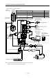
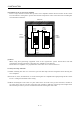
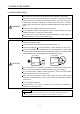
(b) For 1-phase 100V to 120VAC
(Note 2)
Power supply
Circuit breaker
(NFB) or fuse
Magnetic
contactor
(MC)
To CN2
To CN3
To CN1B
To CN1A
L
21
L
11
Protective earth (PE) terminal
Servo motor
Personal
computer
UVW
MR Configurator
(Servo configuration
software
MRZJW3-SETUP151E)
Servo amplifier
Regenerative option
D
P
C
CHARGE
Control circuit terminal block
(Note 1)
Encoder cable
(Note 1)
Power supply lead
L1
L
2
Power
factor
improving
reactor
(FR-BAL)
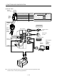
Options and auxiliary equipment
Circuit breaker
Magnetic contactor
Reference
Section 14.2.2
Section 14.2.2
Options and auxiliary equipment
Reference
Cables
Manual pulse generator
External digital display
Section 14.2.1
Section 14.1.8
Section 14.1.7
Power factor improving reactor
Section 14.2.3
Junction terminal block
Manual pulse generator
External digital display
Command device
MR Configurator
(Servo configuration software)
Regenerative option
Chapter 6
Section 14.1.1
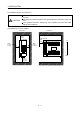
Note 1. The HC-SFS, HC-RFS, HC-UFS 2000 r/min series have cannon connectors.
2. Refer to section 1.2 for the power supply specification.