
Instruction manual

3 - 25
3. SIGNALS AND WIRING
3.7 Input power supply circuit
CAUTION
Always connect a magnetic contactor (MC) between the main circuit power supply
and L
1, L2, and L3 of the servo amplifier, and configure the wiring to be able to shut
down the power supply on the side of the servo amplifier’s power supply. If a
magnetic contactor (MC) is not connected, continuous flow of a large current may
cause a fire when the servo amplifier malfunctions.
Use the trouble signal to switch power off. Otherwise, a regenerative transistor
fault or the like may overheat the regenerative resistor, causing a fire.
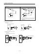
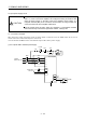
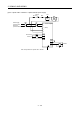
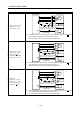
3.7.1 Connection example
Wire the power supply and main circuit as shown below so that the servo-on (SON) turns off as soon as
alarm occurrence is detected and power is shut off.
A circuit breaker (NFB) must be used with the input cables of the power supply.
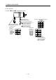
(1) For 3-phase 200 to 230VAC power supply
RA
OFF
ON
MC
MC
SK
NFB MC
L
1
L2
L3
L
11
L
21
EMG
SON
SG
VDD
COM
ALM RA
3-phase
200 to 230 VAC
Forced stop
Servo-on
Trouble
Servo amplifier
Forced
stop