MITSUBISHI ELECTRIC MELSERVO Servo amplifier and motors Instruction Manual MR-J2S-B/B4 Art.-No.
Instruction Manual Servo amplifier MR-J2S-B/B4 Art.-N0.
About this Manual The text, illustrations, diagrams and examples in this manual are solely for clarification purposes for the installation, handling and operation of the servo motors and amplifiers of the MELSERVO J2-Super-Series. If you have any questions concerning the programming and operation of the equipment described in this manual, please contact your relevant sales office or department (refer to back of cover).
Safety Instructions General safety instructions For qualified staff only This manual is intended exclusively for acknowledged and qualified electricians who are totally conversant with the safety standards of electrical drive and automation technology. Project management, installation, setup, maintenance and testing of the equipment must be carried out by an acknowledged and qualified electrician who is totally conversant with the safety standards of electrical drive and automation technology.
Special instructions for working with this manual In this manual special warnings that are important for the proper and safe use of the products are clearly identified as follows: m b NOTE DANGER: Personnel health and injury warnings. Failure to observe the precautions described here can result in serious health and injury hazards. CAUTION: Equipment and property damage warnings. Failure to observe the precautions described here can result in serious damage to the equipment or other property.
Compliance with EC Directives EC directives are intended to allow the liberal sales of goods within the EU. With the establishment of “essential safety regulations” the EC directives ensure that technical barriers to trade between member states of the EU are excluded.
Special safety instructions The following notes on sources of danger should be interpreted as general guidelines for servo drives in association with other devices. These precautions must always be observed in the design, installation and operation of all control systems. m DANGER: ● Observe all safety and accident prevention regulations applicable to your specific application.
Special safety instructions for the devices b CAUTION: ● During the installation of servo systems beware of the heat that builds up during operation. Make sure that there is adequate clearance between the individual modules and enough ventilation to allow the heat to be dissipated. ● Never install servo amplifiers or servo motors or the optional brake unit close to easily flammable materials.
Configuration Control power supply Reinforced insulating transformer No-fuse breaker Power supply NFB Servo motor Magnetic contactor MC Servo amplifier M S00500C Environment Operate the servo amplifier at or above the contamination level 2 set forth in IEC60664-1. For this purpose, install the servo amplifier in a control box which is protected against water, oil, carbon, dust, dirt, etc. (IP54).
Wiring The cables are connected via insulated tubular cable sockets to the terminal strip of the servo amplifier. Crimping terminal Insulating tube Cable S00502C Use only the connectors designed for it to attach the servo motor to the servo amplifier. The connectors can be ordered as accessories.
VIII
Contents Contents 1 Introduction 1.1 Features and configuration . . . . . . . . . . . . . . . . . . . . . . . . . . . . . . . . . . . . . . . . . . . . 1-1 1.2 Function block diagram . . . . . . . . . . . . . . . . . . . . . . . . . . . . . . . . . . . . . . . . . . . . . . . 1-2 1.2.1 Servo amplifiers 200V . . . . . . . . . . . . . . . . . . . . . . . . . . . . . . . . . . . . . . . . . . . 1-2 1.2.2 Servo amplifiers 400V . . . . . . . . . . . . . . . . . . . . . . . . . . . . . . . . . . . . . . . .
Contents 4 Operation 4.1 Points to check prior to starting operation . . . . . . . . . . . . . . . . . . . . . . . . . . . . . . . . . 4-1 4.2 Procedures before Operation. . . . . . . . . . . . . . . . . . . . . . . . . . . . . . . . . . . . . . . . . . . 4-3 4.2.1 Start up procedure . . . . . . . . . . . . . . . . . . . . . . . . . . . . . . . . . . . . . . . . . . . . . . 4-3 4.3 Display and Operation . . . . . . . . . . . . . . . . . . . . . . . . . . . . . . . . . . . . . . . . . . . . . . . .
Contents 8 Maintenance and Inspection 8.1 Inspection. . . . . . . . . . . . . . . . . . . . . . . . . . . . . . . . . . . . . . . . . . . . . . . . . . . . . . . . . . 8-1 8.2 Life . . . . . . . . . . . . . . . . . . . . . . . . . . . . . . . . . . . . . . . . . . . . . . . . . . . . . . . . . . . . . . . 8-1 9 Troubleshooting 9.1 Alarms and Warnings. . . . . . . . . . . . . . . . . . . . . . . . . . . . . . . . . . . . . . . . . . . . . . . . . 9-1 9.1.1 Alarms and warning list . . . . . . . . .
Contents XII
Features and configuration 1 Introduction 1.1 Features and configuration Introduction Apart from possessing the functions of the servo amplifiers MR-J2-Series, the servo amplifiers MR-J2-Super have additional features and functions. The servo amplifiers MR-J2S-B and MR-J2S-B4 are designed for operation with a MitsubishiMotion-Controller via a serial bus (SSCNET). For this the servo amplifier reads in the position data directly so that it can then execute the positioning process.
Introduction Function block diagram 1.2 Function block diagram 1.2.
Function block diagram 1.2.
Introduction Function block diagram MR-J2S-350B4 to 700B4 Regenerative brake option Power supply 3-phase, 380–480VAC Servoverstärker I> L1 I> L2 I> L3 P C Servo motor N U Main circuit U V V W W M Fan Power supply 24VDC + − 24 V • L 1 1 Control circuit power supply 0 V • L 21 24VDC Regenerative brake Base amplifier Voltage detection Overcurrent protection Current detection Electromagnetic brake CN2 EMG Encoder Position command input Virtual motor Model position control
Model overview Introduction 1.3 Model overview 1.3.
Introduction 1.3.2 Model overview Servo amplifiers 400V MR-J2S-200B4 or less MR-J2S-350B4 and MR-J2S-500B4 MR-J2S- B4 Series Code Power supply 4 380–480VAC Code Compatible servo motors HC-SFS MR-J2S-700B4 60 524 100 1024 200 1524/2024 350 3524 500 5024 700 7024 S001196C, S001060E, S001061E Fig. 1-5: Model designation of servo amplifiers 400V 1.3.
Model overview 1.3.4 Introduction Servo motors HC-MFS series HC-KFS series HC-SFS series HC-RFS series S000849C Fig. 1-7: Servo motors Servo motors 200V HC - MFS Motor series HC-MFS HC-KFS HC-SFS HC-RFS Code Electromagnetic brake — — B ✓ Code Rated speed [r/min] 2 2000 3 3000 Code Rated speed [r/min] Code Rated output [W] 05 50 10 1000 31 100 15 1500 2 200 20 2000 4 400 35 3500 5 500 50 5000 7 750 70 7000 Fig.
Introduction Model overview Servo motors 400V HC - SFS 4 Motor series HC-SFS Code Electromagnetic brake — — B ✔ Code Power supply 4 400 V Code Rated speed [r/min] 2 2000 Code Rated output [W] Code Rated output [W] 5 500 35 3500 10 1000 50 5000 15 1500 70 7000 20 2000 Fig.
Model overview Introduction MITSUBISHI AC SERVO MOTOR Model Serial number Production date HC-MFS23 SERIAL DATE MITSUBISHI ELECTRIC CORPORATIO N S00805C Fig.
Introduction 1.4 Removal and reinstallation of the front cover Removal and reinstallation of the front cover For models MR-J2S-200B or larger the front cover must be removed before the battery holder and terminal strips for connecting the power supply of the motor TE1) and control voltage (TE2) are accessible. m DANGER: Prior to removing the front cover the power supply must be switched off and at least 10 minutes must then elapse.
Removal and reinstallation of the front cover Introduction Removal the front cover for MR-J2S-500B, MR-J2S-350B4 and MR-J2S-500B4 Hold down the removing knob. Pull the front cover toward you. Abb. 1-13: Removal the front cover S000909C Reinstallation the front cover for MR-J2S-500B, MR-J2S-350B4 and MR-J2S-500B4 Insert the front cover hooks into the front cover sockets of the servo amplifier. Press the front cover against the servo amplifier until the removing knob clicks. Abb.
Introduction Removal and reinstallation of the front cover Removal the front cover for MR-J2S-700B and MR-J2S-700B4 Press the lock on the side of the front cover inwards. Put a finger in the recess in the middle of the front cover and pull it off to the front. Abb. 1-15: Removal the front cover S000911C Reinstallation the front cover for MR-J2S-700B and MR-J2S-700B4 Insert the front cover hooks into the front cover sockets of the servo amplifier.
Operating elements Introduction 1.5 Operating elements 1.5.1 Servo amplifier 200V Servo amplifier MR-J2S-350B or less 3456 78 9A F012 F0 12 MR-J2S-100B or less BC DE 789A BC DE 3456 MR-J2S-200B and MR-J2S-350B S000970C Fig. 1-17: Servo amplifier MR-J2S-350B or less Name Description Reference Battery holder Contains the battery (optional) for absolute position data backup. Chap. 6 Battery connector (CON1) Used to connect the battery. Section 6.1.
Introduction Operating elements MR-J2S-100B or less MR-J2S-200B and MR-J2S-350B S000512C Fig. 1-18: Servo amplifier MR-J2S-350B or less No. Name Description Bus cable connector (CN1A) Used to connect the servo system controller or Section 3.1.3 preceding axis servo amplifier.
Operating elements Introduction Servo amplifier MR-J2S-500B and MR-J2S-700B 78 9A BC DE 3456 F012 S000971C Fig. 1-19: Servo amplifier MR-J2S-500B and MR-J2S-700B Name Description Reference Battery holder Contains the battery (optional) for absolute position data backup. Chap. 6 Battery connector (CON1) Used to connect the battery. Section 6.1.4 Display The two-digit, seven-segment LED shows the servo status and alarm number. Section 4.
Introduction Operating elements S000916C Fig. 1-20: Servo amplifier MR-J2S-500B and MR-J2S-700B No. Name Description Reference Bus cable connector (CN1A) Used to connect the servo system controller or Section 3.1.3 preceding axis servo amplifier. Bus cable connector (CN1B) Used to connect the subsequent axis servo amplifier or termination connector (MR-A-TM) Communication connector (CN3) Used to connect a personal computer or output Section 3.1.
Operating elements 1.5.2 Introduction Servo amplifier 400V Servo amplifier MR-J2S-60B4 to MR-J2S-200B4 9A F 012 CHARGE LED1 LED2 DE 3456 78 BC SW1 S001238C Fig. 1-21: Servo amplifier MR-J2S-60B4 to MR-J2S-200B4 Name Description Reference Battery holder Contains the battery (optional) for absolute position data backup. Chap. 6 Battery connector (CON1) Used to connect the battery. Section 6.1.
Introduction Operating elements S001198C Fig. 1-22: Servo amplifier MR-J2S-60B4 to MR-J2S-200B4 No. Name Description Reference Main circuit connector (CNP1) Used to connect the input power supply Section 3.1.3 Bus cable connector (CN1A) Used to connect the servo system controller Section 3.1.3 or preceding axis servo amplifier. Bus cable connector (CN1B) Used to connect the subsequent axis servo amplifier or termination connector (MR-A-TM) Section 3.1.
Operating elements Introduction Servo amplifier MR-J2S-350B4 to MR-J2S-700B4 CDE 3456 7 89 A B F 01 2 S000971C Fig. 1-23: Servo amplifier MR-J2S-350B4 to MR-J2S-700B4 Name Description Reference Battery holder Contains the battery (optional) for absolute position data backup. Chap. 6 Battery connector (CON1) Used to connect the battery. Section 6.1.4 Display The five-digit, seven-segment LED shows the servo status and alarm number. Section 4.
Introduction Operating elements MR-J2S-350B4 and MR-J2S-500B4 MR-J2S-700B4 S000916C Fig. 1-24: Servo amplifier MR-J2S-350B4 to MR-J2S-700B4 No. Name Description Reference Bus cable connector (CN1A) Used to connect the servo system controller Section 3.1.3 or preceding axis servo amplifier. Bus cable connector (CN1B) Used to connect the subsequent axis servo amplifier or termination connector (MR-A-TM) Section 3.1.
Operating elements 1.5.3 Introduction Servo motor S000882C Fig. 1-25: Servo motor No. Name Description Reference Encoder connector Cable for connection of encoders Section 7.1.3 Power supply connector, brake Power supply cable (U, V, W), Earth cable, Brake (for motor with electromagnetic brake) Section 3.2 Servo motor shaft Section 2.1.2 Shaft of servo motor Tab.
Introduction 1.6 Functions Functions Function Description Reference High-resolution encoder Motor encoder has a resolution of 131072 pulses/rev. — Absolute position detection system Merely setting a home position once makes home position return unnecessary at every power-on. Chap. 6 Adaptive vibration suppression control Servo amplifier detects mechanical resonance and sets filter characteristics automatically to suppress mechanical vibration. Section 5.1.
System configuration 1.7 b 1.7.1 Introduction System configuration CAUTION: To prevent an electric shock, always connect the protective earth (PE) terminal of the servo amplifier to the protective earth (PE) of the control box.
Introduction System configuration System configuration for MR-J2S-200B and MR-J2S-350B Power supply Serco system controller or preceding axis servo amplifier Servo amplifier No-fuse circuit breaker Subsequent axis servo amplifier or termination connector Magnetic contactor Personal computer (optional) Protective earth terminal Regenerative brake option Encoder cable Servo motor power supply Servo motor S001004C Fig.
System configuration Introduction System configuration for MR-J2S-500B Power supply No-fuse circuit breaker Serco system controller or preceding axis servo amplifier CN1A Subsequent axis servo amplifier or termination connector Magnetic contactor CN1B L1, L2, L3 Regenerative brake option CN3 P, C Protective earth terminal Personal computer (optional) L21, L11 CN2 Servo motor power supply Encoder cable Servo motor S001005C Fig.
Introduction System configuration System configuration for MR-J2S-700B Power supply Serco system controller or preceding axis servo amplifier No-fuse circuit breaker CN1A Subsequent axis servo amplifier or termination connector CN1B Magnetic contactor CN3 L21, L11 Personal computer (optional) P, C CN2 Protective earth terminal L1, L2, L3 Regenerative brake option Encoder cable Servo motor power supply Servo motor S001006C Fig.
System configuration 1.7.
Introduction System configuration System configuration for MR-J2S-350B4 and MR-J2S-500B4 Power supply No-fuse circuit breaker Serco system controller or preceding axis servo amplifier Subsequent axis servo amplifier or termination connector CN1A CN1B Servo amplifier Magnetic contactor CN3 L1, L2, L3 Regenerative brake option Personal computer P, C + - Power supply 24VDC Circuit protector Protective earth terminal CN2 Servo motor power supply Encoder cable Servo motor S001253C Fig.
System configuration Introduction System configuration for MR-J2S-700B4 Power supply Serco system controller or preceding axis servo amplifier CN1A No-fuse circuit breaker Subsequent axis servo amplifier or termination connector CN1B Servo amplifier CN3 Magnetic contactor Personal computer + Power supply - 24VDC Circuit protector P, C L1, L2, L3 CN2 Protective earth terminal Regenerative brake option Encoder cable Servo motor power supply Servo motor S001254C Fig.
Introduction 1 - 30 System configuration
General environmental conditions Installation 2 Installation 2.1 General environmental conditions b CAUTION: ● The equipment must be installed in the specified direction. Otherwise, a fault may occur. ● Leave specified clearances between the servo amplifier and control box inside walls or other equipment. Environmental conditions Data Servo amplifier Ambient temperature during operation 0 to +55°C (non-freezing) Servo motor 0 to +40°C (non-freezing) Ambient humidity during operation Max.
Installation 2.1.1 b General environmental conditions Installation of servo amplifiers CAUTION: ● When installing the unit in a control box, prevent drill chips and wire fragments from entering the servo amplifier. ● Prevent oil, water, metallic dust, etc. from entering the servo amplifier through openings in the control box or a fan installed on the ceiling.
General environmental conditions Installation Installation of two or more servo amplifiers and other equipment Leave a large clearance between the top of the servo amplifier and the internal surface of the control box. Due to the power loss of the units it must be ensured that the internal temperature of the control cabinet does not exceed the ambient temperature of +55 °C allowed for the servo amplifier. If necessary, the control cabinet will have to be ventilated.
Installation 2.1.2 General environmental conditions Installation of servo motors Safety instructions b CAUTION: ● Do not hold the cable, shaft or encoder to carry the servo motor. Otherwise, a fault or injury may occur. ● Securely fix the servo motor to the machine. If fixed insecurely, the servo motor will come off during operation, leading to injury. ● When coupling the shaft end of the servo motor, do not subject the shaft end to impact, such as hammering. The encoder may become faulty.
General environmental conditions Installation ● For installation of the servo motor, use spring washers, etc. and fully tighten the bolts so that they do not become loose due to vibration. ● When using a pulley, a chain wheel or synchronising pulley select a diameter that will not exceed the permissible radial load (see table below). ● Do not use any inelastic, rigid connections that may lead to excessive bending moments to the shaft and thus cause the shaft to break.
Installation General environmental conditions Vibration Servo motor Vibration HC-KFS HC-MFS X, Y: 49m/s2 (5g) (refer fig. 2-6) HC-SFS52 to 152 HC-SFS524 to 1524 HC-RFS X, Y: 24.5m/s2 (2.5g) (refer fig. 2-6) HC-SFS202, 352 HC-SFS2024, 3524 X: 24.5m/s2 (2.5g) Y: 49m/s2 (5g) (refer fig. 2-6) HC-SFS502, 702 HC-SFS5024, 7024 X: 24.5m/s2 (2.5g) Y: 29.4m/s2 (3g) (refer fig. 2-6) Fig.
General environmental conditions Installation Protection from oil and water When the gear box is mounted horizontally, the oil level in the gear box should always be lower than the oil seal lip on the servo motor shaft. If it is higher than the oil seal lip, oil will enter the servo motor, leading to a fault. Make sure there is a ventilation hole in the gear box to prevent any pressure build up in the gear box.
Installation General environmental conditions When installing the servo motor horizontally, face the power cable and encoder cable downward. When installing the servo motor vertically, lay the cables with an adequate cable trap to avoid mechanical load on the cable and motor. Cable trap S000526C Fig. 2-9: Installing the servo motor horizontally and vertically showing cable trap Make sure that the cables leading to the servo motor does not pass through oil or water.
General environmental conditions Installation Gear Lubricating oil Servo motor S000528C Fig. 2-11: Installation of the motor with the shaft at the top In general the installation of the servo motor can be in any desired location or position. When the servo motor with electromagnetic brake is installed with the shaft end at top, the brake plate may generate sliding sound but it is not a fault.
Installation 2 - 10 General environmental conditions
Connection of servo amplifier Connection 3 Connection 3.1 Connection of servo amplifier b 3.1.1 CAUTION: Only the voltage stated may be connected to the relevant terminals. An incorrect voltage can lead to damage to the servo amplifier.
Connection 3.1.
Connection of servo amplifier Connection Connectors Servo amplifier Main circuit/control circuit/ brake restistor/brake unit CNP1 CHARGE CNP3 CN4 OPEN CNP1 C N 1 A C N 1 B L1 L1 P U 24 V/L11 L2 C V 0 V/L21 L3 D W L2 L3 P C N 2 E N C C CNP2 D C N 3 ( ( MR-J2S-60B4 to MR-J2S-200B4 CNP2 Protective earth PE N 24V L11 U CNP3 V N 0V L21 W PE S001204C S001227C Servo amplifier 400V TE1 TE1 MR-J2S-350B4 to MR-J2S-500B4 S001208C Mounting screw for interna brake resisto
Connection Connection of servo amplifier Main circuit terminal overview for MR-J2S-60B to MR-J2S-700B Terminal Signal Description L1, L2, L3 Main circuit power supply The rated voltage range is 3-phase 200 to 230V AC, 50/60 Hz. Up to 750 W a 1-phase power supply is possible. L11, L21 Control circuit power supply The rated voltage range is 1-phase 200 to 230V AC, 50/60 Hz. Here L11 must be equal in phase to L1 and L21 equal in phase to L2.
Connection of servo amplifier 3.1.3 Connection Signal lines The servo amplifier has four signal connectors. You will find the pin configuration of the connectors on the next page.
Connection Connection of servo amplifier Interface explanations Connector Name Description CN1A Connector for bus cable from preceding axis. Used for connection with the controller or preceding-axis servo amplifier. CN1B Connector for bus cable to next axis Used for connection with the next-axis servo amplifier or for connection of the termination connector. CN2 CN3 Encoder connector Used for connection with the servo motor encoder.
Connection of servo amplifier 3.1.4 Connection Interfaces The connection of external periphery to the interface described in section 3.1.3 is covered in the following. Digital input interface DI-1 Give a signal with a relay or open collector transistor. Servo amplifier VD D COM 24V D C 4.7 kΩ app ro x. 5 m A EM 1 Tr SG U C ES ≤ 1V I C EO ≤ 100 µA S001007C Fig.
Connection Connection of servo amplifier Digital output interface DO-1 Via this interface a control lamp, a relay or an photocoupler may be addressed, for example. Provide a diode (D) for an inductive load, or an inrush current suppressing resistor (R) for a lamp load. (Permissable current: 40mA, inrush current: 100mA). ● Inductive Load Servo amplifier 24 V DC VDD D MBR Tr SG S001008C Fig.
Connection of servo amplifier Connection Emulated encoder output ● Differential output max. output current: 35mA Servo amplifier Servo amplifier AM26LS32 or equivalent LA (LB, LZ) 150 Ω LAR (LBR, LZR) LA (LB, LZ) 1,2k Ω LAR (LBR, LZR) & High-speed photocoupler LG SD SD S000553C Fig. 3-5: Example A R T B R π/2 LZ/LZR signal varies ±3/8T on its leading edge. Z R > 40 0 µs P n S000554C Fig.
Connection Servo motor 3.2 Servo motor 3.2.1 Connection of servo motors b CAUTION: ● Ground the servo amplifier and servo motor securely. To prevent an electric shock, always connect the protective earth terminal (PE) of the servo amplifier marked with , with the protective earth of the control box. ● Connect the cables to the servo amplifier and servo motor with the right terminals and the correct phases (U, V, W) . Otherwise the servo motor will not work correctly.
Servo motor 3.2.2 Connection Motor connector Servo motor series HC-KFS (B)/HC-MFS (B) Power supply connector Red: Phase U White: Phase V Black: Phase W Green/yellow: Protective earth Encoder connector Brake connector S000883C Fig.
Connection Servo motor Servo motor series HC-SFS/HC-RFS Power supply connectors Brake connector Encoder connector S000562C Fig.
Servo motor Connection A M G A F B E L A D A B C B K F H E C G D P S R H D Power supply connector MR-PWCNS1 Power supply connector MR-PWCNS2 Power supply connector MR-PWCNS3 Pin Signal Pin Signal Pin Signal A U A U A U B V B V B V C W C W C W D Protective earth D Protective earth D Protective earth C T J C B N G D B E F Encoder MR-J2CNS (Set) Pin Signal Pin A MD K — Pin B MDR L — A B1 C MR M — B B2 D MRR N SD E — P
Connection 3.3 Internal circuit and common Internal circuit and common Servo amplifier 24 V DC VDD COM MBR EM1 Digital input interface SG LA, etc. LAR, etc. Differential output 35mA max. LG SD MO1 MO2 LG Analog output TXD RS232C RXD CN2 MR MRR LG Input encoder SD S000976C Fig.
Grounding 3.4 m Connection Grounding DANGER: ● Ground the servo amplifier and servo motor securely. ● To prevent an electric shock, always connect the protective earth terminal (PE) of the servo amplifier marked with , with the protective earth of the control box. Control box Power supply 200-230V 50Hz Servo amplifier Line filter MC Servo motor CN2 L1 Encoder L2 L3 L11 L21 U V W U V W M Controller CN1A Connect to PE terminal! Protective earth S000983C Fig.
Connection 3.5 m Power supply Power supply DANGER: When the servo amplifier has become faulty, switch power off on the amplifier power side. Power-on procedure Always wire the power supply using the magnetic contactor with the main circuit power supply L1, L2 and L3 or L1 and L2 for 1-phase connection. Switch on the control circuit power supply L11, L21 simultaneously with the main circuit power supply or before switching on the main circuit power supply.
Power supply 3.5.1 Connection Connection example Connection for servo amplifier 200V Connection examples for 1-phase and 3-phase power supplies are illustrated in the following diagrams: Power supply 230V 50Hz ON MC Emergency stop RA Controller emergency stop MC SK Servo amplifier MC L1 L2 L3 L11 L21 VDD COM EM1 SG Emergency stop S000977C Fig.
Connection Power supply Connection for servo amplifier 400V ON RA MC MC Emergency stop OFF SK Power supply 400V 50Hz Transformer Servo amplifier MC L1 L1 L2 L3 L2 L3 P C Circuit protector Power supply 24VDC D + - 2 4 V/L1 1 0 V/L 2 1 EM1 Emergency stop SG VDD COM S001239C Fig.
Power supply Connection Timing chart "Servo ON" command accepted (3s) Main circuit and ON control circuit OFF Base circuit ON OFF 60m s 10m s 60m s Servo ON command ON (from controller) OFF S000979C Fig. 3-19: Timing chart for switching on the power supply Emergency stop For safety’s sake an EMERGENCY OFF switch must always be installed between the terminals EM1 and SG.
Connection 3.6 b Alarm occurence timing chart Alarm occurence timing chart CAUTION: When an alarm has occurred, remove its cause, make sure that the operation signal is not being input, ensure safety, and reset the alarm before restarting operation.
Servo motor with electromagnetic brake 3.7 b Connection Servo motor with electromagnetic brake CAUTION: Configure the electromagnetic brake circuit so that it is activated not only by the interface unit signals but also by a emergency stop.
Connection Servo motor with electromagnetic brake Setting procedure The setting for the electromacnetic brake is as follows: In Parameter 21 set the time delay (Tb) from electromagnetic brake operation to base circuit shut-off, shown in fig. 3-23. Use parameter 30 to set the rotation speed at which the electromagnetic brake is to be activated when there is an alarm or an EMERGENCY OFF.
Servo motor with electromagnetic brake Connection Dynamic brake Dynamic brake, electromagnetic brake Electromagnetic brake Servo motor speed ON Base circuit OFF Electromagnetic brake (MBR) Invalid (ON) Electromagnetic brake operation delay time Valid (OFF) Invalid (ON) Alarm Valid (OFF) S000803E Fig.
Connection 3.8 Examples of standard wiring diagrams Examples of standard wiring diagrams In the following illustrations there is presented a wiring diagram for a 200V and a 400V servo amplifier. NOTE Please take all notes given in this chapter into account. Servo amplifier 200V Make up a sequence which switches off the MC at alarm occurence or emergency stop.
Examples of standard wiring diagrams Connection Servo amplifier 400V Make up a sequence which switches off the MC at alarm occurence or emergency stop.
Connection Examples of standard wiring diagrams m To prevent an electric shock, always connect the protective earth terminal (PE) of the servo amplifier marked with , with the protective earth of the control box. b CAUTION: Do not reverse the diode’s direction. Connecting it backwards could cause the amplifier to malfunction so that signals are not output, and emergency stop and other safety circuits are inoperable. DANGER: Ground the servo amplifier and servo motor securely.
Station number setting 3.9 Connection Station number setting Use the coding switch (CS1) to set the station number for the servo amplifier. If the same numbers are set to different servo amplifier in a single communication system, the system will not operate properly. Set the switch to "F" when executing the test operation mode using the setup-software. NOTE The station number set to CS1 should be the same as the one set to the servo system controller. Abb.
Connection 3 - 28 Station number setting
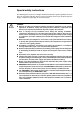
Points to check prior to starting operation Operation 4 Operation 4.1 Points to check prior to starting operation Wiring Before starting operation, check the following: ● A correct power supply is connected to the power input terminals (3-phase: L1, L2, L3, 1-phase: L11, L21) of the servo amplifier. ● The servo motor power supply terminals (U, V, W) of the servo amplifier match in phase with the power input terminals (U, V, W) of the servo motor.
Operation Points to check prior to starting operation ● 24VDC or higher voltages are not applied to the pins of connector CN3. ● SD and SG of connector CN3 are not shorted. SD SG Servo amplifier S000583C Fig. 4-3: Short-circuit of SD and SG ● The connection cable are not under a mechanical load (tension or excessive bend etc.).
Procedures before Operation 4.2 m Operation Procedures before Operation DANGER: ● Do not operate the switches with wet hands. You may get an electric shock. ● Do not operate the controller with the front cover removed. There is the risk of getting an electric shock from live parts. ● During power-on or operation, do not open the front cover. You may get an electric shock. ● Before starting operation, check the parameters.
Operation Procedures before Operation Servo on Switch the servo-on in the following procedure: Switch on main circuit and control circuit power supply. The controller transmits the "servo ON" command. When placed in the "servo ON" status, the servo amplifier is ready to operate and the servo motor is locked. Home position return Always perform home position return before starting positioning operation.
Display and Operation Operation 4.3 Display and Operation 4.3.1 Display sequence On the servo amplifier display (two-digit, seven-segment display), check the status of communication with the servo system controller at power-on, check the station number, and diagnose a fault at occurrence of an alarm.
Operation 4.3.2 Display and Operation Indication list Display Status Description AA Initializing The servo amplifier was switched on when power to the servo system controller is off. Power to the servo system controller was switched off during power-on of the servo amplifier. Ab The station number set to the servo system controller does not match the station number set with the coding switch (CS1) of the servo amplifier.
Test operation mode 4.4 b Operation Test operation mode CAUTION: ● The test operation mode is designed for servo operation confirmation and not for machine operation confirmation. Do not use this mode with the machine. Always use the servo motor alone. ● If an operation fault occurred, use the forced stop (EM1) to make a stop.
Operation Test operation mode ● Positioning operation Positioning operation can be performed without using the servo system controller. This operation may be used independently of whether the servo is on or off and whether the servo system controller is connected or not. Exercise control on the positioning operation screen of the setup-software.
Test operation mode Operation ● Motor-less operation Without connecting the servo motor, output signals or status displays can be provided in response to the servo system controller commands as if the servo motor is actually running. This operation may be used to check the servo system controller sequence. Use this operation with the servo amplifier connected to the servo system controller. NOTE Motor-less operation may be used with the setup-software.
Operation 4.4.1 Test operation mode Test operation procedure JOG operation, positioning operation, program operation, forced output Switch power off. Set the coding switch CS1 to „F“. When CS1 is set to the station number and operation is performed by the servo system controller, the test operation mode screen is displayed on the personal computer, but no function is performed. Switch servo amplifier power on.
Parameter 4.5 Operation Parameter When the servo amplifier is connected with the servo system controller, the parameters are set to the values of the servo system controller. Switching power off, then on makes the values set on the setup-software invalid and the servo system controller values valid. NOTES In the maker setting parameters, do not set any values other than the initial values.
Operation 4.5.2 Parameter Parameter overview Function Basic parameters Adjustment parameters No.
Parameter Operation Function Expansion parameters No. Symbol Name Initial value Unit 27 MO1 Analog output 1 offset 0 mV 28 MO2 Analog output 2 offset 0 mV 29 — Reserved 0001 — 30 ZSP Zero speed 50 r/min 31 ERZ Error excessive alarm level 80 0.
Operation 4.5.3 Parameter Parameter description: Number Symbol Initial value 1 AMS 0000 Unit Setting range Refer description Amplifier setting Used to select the absolute position detection.
Parameter Operation Number Symbol Initial value 6 FBP 0 Unit Setting range Refer description Feedback pulse number Set the number of pulses per revolution in the controller side command unit. Information on the motor such as the feedback pulse value, present position, droop pulses and within-one-revolution position are derived from this setting.
Operation Parameter Number Symbol Initial value 9 RSP 0005 Unit Setting range Refer description Response auto tuning Used to select the response of auto tuning. 0 0 0 Value Response characteristic Machine resonance frequency 1 Low 15Hz 2 20Hz 3 25Hz 4 30Hz 5 35Hz 6 45Hz 7 55Hz 8 Middle 70Hz 9 85Hz A 105Hz B 130Hz C 160Hz D 200Hz E 240Hz F 10 TLP High 300 300Hz % 0–500 Forward rotation torque limit Assume that the maximum rated torque is 100%.
Parameter Operation Number Symbol Initial value Unit Setting range 14 VG1 177 rad/s 20–5000 Speed control gain1 If auto tuning 1 or 2 (parameter 8) or interpolation mode is selected, then this parameter will optimise itself automatically. If auto tuning or interpolation mode is de-selected, then this parameter should not be changed. Higher setting increases the response level but is liable to generate vibrations.
Operation Parameter Number Symbol Initial value Unit Setting range 19 FFC 0 % 0–100 Feed forward gain Pre-regulation to minimise the control deviation for position control. When the setting is 100%, the droop pulses during operation at constant speed are nearly zero. However, sudden acceleration/deceleration will increase the overshoot. 20 INP 100 Pulse 0–50000 In-position range Used to set the droop pulse range in which the in-position will be output to the controller.
Parameter Operation Number Symbol Initial value 24 OP2 0000 Unit Setting range Refer description Function selection 2: Used to select slight vibration suppression control and motor-less operation 0 0 Used to suppress vibration at a stop. Made this function valid when auto tuning selection is set to "0002" in parameter No. 8.
Operation Parameter Number Symbol Initial value Unit Setting range 27 MO1 0 mV −999–999 mV −999–999 r/min 0–10000 Analog monitor 1 offset Used to set the offset voltage of the analog monitor 1 (MO1) output. 28 MO2 0 Analog monitor 2 offset Used to set the offset voltage of the analog monitor 2 (MO2) output. 29 0001 Reserved Do not change this parameter. 30 ZSP 50 Entry of the rotation speed under which the output signal “Rotation speed “ is output. 31 ERZ 80 0.
Parameter Operation Number Symbol Initial value Unit Setting range 34 VPI 0 Pulse 0–50000 PI-/PID control switch-over position droop Setting the switching threshold of the contouring error (in pulses) for the switch-over from PI to PID control. Set "0001" in parameter No. 32 to make this function valid. 35 0 Reserved Do not change this parameter. 36 VDC 980 r/min 0–1000 Speed differential compensation If auto tuning (pr. 8) is selected then this parameter optimises itself automatically.
Operation Parameter Number Symbol Initial value 40 BLK 0000 Unit Setting range Refer description Parameter entry prohibition Depending on the setting, various parameter ranges may be blocked for reading or writing (refer topage 4-11). Setting Function 0000 (Initial value) Read 000A Write Read Write Operation from controller Operation from setup-software Parameter No. 1 to No. 39 Parameter No. 1 to No. 11 and No. 40 Parameter No. 1 to No. 39 Parameter No.
Gain Operation 4.6 Gain 4.6.1 Gain adjustment The gain adjustment in this section can be made on a single servo amplifier. For gain adjustment, first execute auto tuning mode 1.
Operation Gain For the gain setting please follow the instructions which are given below: Usage Start Interpolation mode for 2 or more axes Used when you want to match the position gain (PG1) between 2 or more axes. Yes Interpolation mode No Operation Allows adjustment by merely changing the response level setting. First use this mode to make adjustment.
Gain 4.6.2 Operation Gain adjustment using setup-software The following table shows the functions and adjustment when using the setup-software: Function Description Adjustment Machine analyzer The characteristic of the whole mechanical system can be registered from the personal computer. You can grasp the machine resonance frequency and determine the notch frequency of the machine resonance suppression filter. You can automatically set the optimum gains in response to the machine characteristic.
Operation 4.6.3 Gain Auto tuning The servo amplifier is equipped with a real-time auto tuning function that constantly optimises the gain factors of the control loops depending on the machine characteristics (inertia of mass ratio). This allows time-consuming settings during start-up to be avoided. Auto tuning 1 The servo amplifier is factory-set to the auto tuning mode 1. In this mode, the inertia ratio of a machine is always estimated to set the optimum gains automatically.
Gain Operation Auto tuning mode operation The block diagram of real-time auto tuning is shown below: Load inertia moment Automatic setting Encoder Control gain PG1, VG1, PG2, VG2, VIC + Command - + - Current control Servo motor Current feedback Set 0 or 1 to turn on Real-time auto tuning section Gain table S1 Parameter No. 9 Parameter No. 8 0 0 0 1 Auto tuning 0 0 0 5 Position/speed feedback Mass inertia ratio estimation Pr. 12: Mass inertia ratio Response level S000987C Fig.
Operation Gain Adjustment procedure by auto tuning Auto tuning is the standard selection. In most cases you just need to connect the motor and start up without making any time-consuming settings. Simply turn on the response level of auto tuning in order to carry out the setting procedure. Auto tuning Acceleration/deceleration repeated Yes Mass inertia ratio estimation No Choose the auto tuning mode 2 (parameter No. 8: 0003) and set the load inertia moment ratio (parameter No. 12) manually.
Gain Operation Response level setting in auto tuning mode Set the response (parameter No. 9) of the whole servo system. As the response level setting is increased, the trackability and positioning time for a command decreases, but a too high response level will generate vibration. Hence, make setting until desired response is obtained within the vibration-free range.
Operation 4.6.4 Gain Manual gain setting If you are not satisfied with the adjustment of auto tuning, you can make simple manual adjustment with three parameters. Manual mode 1 In this mode, setting the three gains of position control gain 1 (PG1), speed control gain 2 (VG2) and speed integral compensation (VIC) automatically sets the other gains to the optimum values according to these gains. The setting of the inertia of mass ratio occurs in pr. 12.
Gain Operation ● Speed control The following table gives an overview of the parameters used for rotation speed control for the manual setting of the gain factor. Parameter Symbol Name 12 GD2 Ratio of load inertia moment to servo motor inertia moment 16 VG2 Speed control gain 2 17 VIC Speed intergral compensation Tab. 4-19: Parameter adjusted for speed control For the setting please follow the instructions which are given below: Set an estimated value to the ratio of inertia (parameter No.
Operation Gain ● Position control The following table gives an overview of the parameters used for position control for the manual setting of the gain factor. Parameter Symbol Name 12 GD2 Ratio of load inertia moment to servo motor inertia moment 13 PG1 Position control gain 1 16 VG2 Speed control gain 2 17 VIC Speed intergral compensation Tab.
Gain 4.6.5 Operation Interpolation The interpolation mode is used to match the position control gains of the axes when performing the interpolation operation of servo motors of two or more axes for an X-Y table or the like. In this mode, the position control gain 1 and speed control gain 1 which determine command trackability are set manually and the other gain adjusting parameters are set automatically.
Operation 4.6.6 Gain Differences in auto tuning between MR-J2 and MR-J2S Response level In comparison to the servo amplifiers of the MR-J2-Series the area for setting response levels has been extended for servo amplifiers of the MR-J2-Super-Series. 0 0 0 5 Response level S000988C Fig. 4-10: Response level setting (parameter No.
Gain Operation Auto tuning selection The MR-J2-Super series has an addition of the load inertia moment ratio fixing mode. It also has the addition of the manual mode 1 which permits manual adjustment with three parameters. 0 0 0 1 Auto tuning selection S000989C Fig. 4-11: Auto tuning selection (parameter No.
Operation 4 - 36 Gain
Filter functions 5 Special adjustment functions Special adjustment functions Use the functions given in this chapter, if you are not satisfied with the machine status after making adjustment in the methods in section 4.6. 5.
Special adjustment functions 5.1.1 Filter functions Machine resonance suppression filter The machine resonance suppression filter is a notch filter. You can set the resonance frequency and notch frequency. Mechanical system response level Resonance point Frequency Filter curve Notch frequency Frequency S000876C Fig. 5-2: Mode of operation of the filter for the suppression of machine resonance NOTE 5-2 The machine resonance suppression filter is a delay factor for the servo system.
Filter functions Special adjustment functions Parameter ● Machine resonance suppression filter (pr. 18) Set the notch frequency and attenuation of the machine resonance suppression filter (parameter No.18). 0 Frequency [Hz] Setting Frequency Setting Frequency Setting Frequency Setting Frequency 00 — 08 562.5 10 281.3 18 187.5 01 4500 09 500 11 264.7 19 180 02 2250 0A 450 12 250 1A 173.1 03 1500 0B 409.1 13 236.8 1B 166.7 04 1125 0C 375 14 225 1C 160.
Special adjustment functions 5.1.2 Filter functions Adaptive vibration suppression control Adaptive vibration suppression control is a function in which the servo amplifier detects machine resonance and sets the filter characteristics automatically to suppress mechanical system vibration. Since the filter characteristics (frequency, attenuation) are set automatically, you need not be conscious of the resonance frequency of a mechanical system.
Filter functions Special adjustment functions Parameters Set the operation of adaptive vibration suppression control at the third digit of parameter 25. 0 0 Adaptive vibration suppression control 0: invalid 1: valid The resonance frequency is constantly determined and the filter set accordingly. 2: held Filter characteristics generated so far is held. Adaptive vibration suppression control sensitivity 0: normal sensitivity 1: large sensitivity S000619C Fig.
Special adjustment functions 5.1.3 Filter functions Low-pass filter When a ballscrew or the like is used, resonance of high frequency may occur as the response level of the servo system is increased. To prevent this, the low-pass filter is factory-set to be valid for a torque command. The filter frequency of this low-pass filter is automatically adjusted to the value in the following expression: VG2 × 10 filter frequency [Hz] = -----------------------------------------------2π ( 1 + GD2 × 0.
General description Absolute position detection system 6 Absolute position detection system 6.1 General description b 6.1.1 CAUTION: If an absolute position erase alarm (25) has occurred, always perform home position setting again. Not doing so can cause runaway. Specifications Item Description System Electronic battery backup system Battery Lithium battery A6BAT or MR-BAT Maximum revolution range Reference position ±32767 rev.
Absolute position detection system 6.1.2 General description System configuration Controller Servo amplifier CN1 CN2 CN5 Battery Servo motor S000994 Fig. 6-1: System configuration 6.1.3 Communication overview Block diagram The encoder consists of a detector designed to detect a position within one revolution and a cumulative revolution counter designed to detect the number of revolutions.
General description 6.1.4 b Absolute position detection system Battery installation procedure CAUTION: The internal circuits of the servo amplifier may be damaged by static electricity. Always take the following precautions: ● Ground human body and work bench. ● Do not touch the conductive areas, such as connector pins and electrical parts, directly by hand. For battery installation please follow the instructions which are given below: Open the operation window.
Absolute position detection system 6.1.5 General description Parameter setting Set "0001" in parameter No.1 to make the absolute position detection system valid. 0 0 0 1 Absolute position detection 0: incremental system 1: absolute system S000996C Fig. 6-5: 6-4 Parameter No.
General description 6.1.6 Absolute position detection system Absolute position detection data You can display the absolute position data with the setup software. For this function please follow the instruction which are given below: Clicking "Diagnostics" in the menu. Abb. 6-6: Open the menu "Diagnostics" S000999T By clicking "Absolute Encoder Data" in the sub-menu "Diagnostics", the absolute encoder data display window appears. S001000T Fig.
Absolute position detection system 6-6 General description
Accessories 7 Accessories m DANGER: b CAUTION: Before connecting any option or auxiliary equipment, make sure that the charge lamp is off more than 10 minutes after power-off, then confirm the voltage with a tester or the like. Otherwise, you may get an electric shock. Use the specified auxiliary equipment and options. Unspecified ones may lead to a fault or overheating of the amplifier or regenerative brake resistor.
Accessories Optional accessories 7.1 Optional accessories 7.1.1 Regenerative brake option b CAUTION: Only use the combinations of regenerative brake options and servo amplifiers, which are listed in the following table. Otherwise, a fire may occur. Allowable combinations of regenerative brake resistors/servo amplifiers 200V. Regenerative power [W] Servo amplifier Built-in regenerative brake resistor MR-RFH75-40 (40Ω) MR-RFH220-40 (40Ω) MR-RFH400-13 (13Ω) MR-RFH400-6,7 (6.
Optional accessories Accessories Selection of the regenerative brake option ● Simple selection method In horizontal motion applications, select the regenerative brake option as described below: When the servo motor is run without load in the regenerative mode from the running speed to a stop, the permissible duty is as indicated in tab. 10-4, tab. 10-5 and tab. 10-6 in section 10.2.2.
Accessories Optional accessories ● Regenerative energy calculation Use the following method (refer tab. 7-3) when regeneration occurs continuously in vertical motion applications or when it is desired to make an in-depth selection of the regenerative brake option. TF TU No up Time t1 t2 t3 t4 (+) generative Generated torque Unbalance torque Friction torque M Servo motor speed tf (1 cycle) (− ) Time regenerative S000634C Fig.
Optional accessories Accessories Servo amplifier 400V Servo amplifier 200V ● Power dissipation of servo motor and servo amplifier in regenerative mode Servo amplifier Efficiency [%] regenerative mode Capacitor charging [J] MR-J2S-10B 55 9 MR-J2S-20B 70 9 MR-J2S-40B 85 11 MR-J2S-60B 85 11 MR-J2S-70B 80 18 MR-J2S-100B 80 18 MR-J2S-200B 85 40 MR-J2S-350B 85 40 MR-J2S-500B 90 45 MR-J2S-700B 90 70 MR-J2S-60B4 85 11 MR-J2S-100B4 80 18 MR-J2S-200B4 85 40 MR-J2S-350B4
Accessories Optional accessories ● Installation of regenerative brake option When using the regenerative brake resistor remove the built-in brake resistor and fit the regenerative brake option across P-C. Set parameter No. 2 according to the option to be used. Servo amplifier 200V Servo amplifier 400V Regenerative selection brake option 00: No brake resistor 01: FR-RC, FR-BU 05: MR-RFH220-40 08: MR-RFH400-13 09: MR-RFH400-13 0B: MR-RFH400-6.7 0C: MR-RFH400-6.
Optional accessories Accessories For installation of an external brake resistor to the servo amplifiers MR-J2S-500B and MR-J2S700B and MR-J2S-350B4 to MR-J2S-700B4 always remove the built-in regenerative brake resistor. To do this loosen the cables attached to terminals P and C. Then fasten the cables to the housing of the servo amplifier using the accessory screw (refer fig. 7-5). Always remove built-in regenerative brake resistor! Servo amplifier Regenerative brake option P P x C C x 5m max.
Accessories 7.1.2 Optional accessories Cables Use the following cables for connection of the servo motor and servo amplifier: Servo amplifier Termination connector CN1A CN1B CN1A CN1B CN2 CN3 CN2 CN3 PC (optional) Motor HC-SFS/HC-RFS Motor HC-KFS/ HC-MFS Instructions for connecting the PC can be found in the manual for the Motion Controller. ! S000992C Fig.
Optional accessories 7.1.3 b Accessories Confection diagram of encoder cables CAUTION: If you have fabricated the encoder cable, connect it correctly. Otherwise, misoperation or explosion may occur.
Accessories 7.1.4 b Optional accessories Bus cable CAUTION: When fabricating the bus cable, do not make incorrect connection. Doing so can cause misoperation or explosion.
Special accessories Accessories 7.2 Special accessories 7.2.1 Transformer Input: 3 × 400V Output: 3 × 230V Power capacity ED Input current Output current Terminal cross section Power dissipation MT 1.3-60 1.3kVA 60% 2.02A 2.69A 3.26A 4.27A 2.5mm² 2.5mm² 103W 167W MT 1.7-60 1.7kVA 60% 2.61A 3.89A 4.27A 6.2A 2.5mm² 2.5mm² 110W 199W MT 2.5-60 2.5kVA 60% 3.80A 5.42A 6.28A 8.78A 2.5mm² 2.5mm² 155W 282W MT 3.5-60 5.5kVA 60% 5.30A 8.41A 8.78A 13.80A 4mm² 4mm² 170W 330W MT 5.
Accessories 7 - 12 Special accessories
Inspection Maintenance and Inspection 8 Maintenance and Inspection 8.1 Inspection It is recommended to make the following checks periodically: Check for loose terminal block screws. Retighten any loose screws. Check the servo motor bearings, brake section, etc. for unusual noise. Check the cables and the like for scratches and cracks. At regular intervals check that the various components all function properly. Check the servo motor shaft and coupling for misalignment. 8.
Maintenance and Inspection 8-2 Life
Alarms and Warnings Troubleshooting 9 Troubleshooting 9.1 Alarms and Warnings 9.1.1 Alarms and warning list When a fault occurs during operation, the corresponding alarm or warning is displayed. If any alarm or warning has occurred, refer to section 9.1.2 or section 9.1.3 and take the appropriate action.
Troubleshooting Alarms and Warnings Alarm deactivation Alarme Display Meaning 92 Open battery cable warning 96 Home position setting warning 9F Battery warning E0 Excessive regenerative warning E1 Overload warning E3 Absolute position counter warning E4 Parameter warning E6 Servo forced stop warning E7 Controller emergency stop warning E9 Main circuit off warning EE SSCNET error warning Power OFF ON RESET command CPU reset Removing the cause of occurrence deactivates the alarm
Alarms and Warnings 9.1.2 m Troubleshooting Alarms DANGER: When any alarm has occurred, eliminate its cause, ensure safety, then reset the alarm, and restart operation. Otherwise, injury may occur. If an absolute position erase alarm (25) occurred, always make home position setting again. Otherwise, misoperation may occur. Tab.
Troubleshooting Alarms and Warnings Display Error Definition Cause Action 10 Undervoltage Power supply voltage dropped to 160V (servo amplifier 200V) and 280V (servo amplifier 400V) or less, respecively. 1. Power supply voltage is low. Check the power supply 2. There was an instantaneous control circuit power failure of 60ms or longer. 3. The impedance of the power supply is too high. 4. Main circuit power switched on within 5s after it had switched off. 5.
Alarms and Warnings Troubleshooting Display Error Definition Cause Action 25 Absolute position erase Absolute position data in error 1. Battery voltage low Change battery Always make home position setting again 2. Battery cable or battery is faulty. Power was switched 3. Capacitor of the absolute position on for the first time in encoder is not charged. the absolute position detection system.
Troubleshooting Alarms and Warnings Display Error Definition Cause Action 32 Overcurrent Current that flew is higher than the permissible current of the servo amplifier. 1. Short occurred in servo amplifier output phases U, V and W. Correct the wiring 33 34 Overvoltage CRC error Converter bus voltage exceeded 400V (servo amplifier 200V) and 800V (servo amplifier 400V) respecively. Bus cable is faulty. Change the servo 2. Transistor of the servo amplifier amplifier faulty.
Alarms and Warnings Troubleshooting Display Error Definition 37 Parameter error Parameter setting is 1. Servo amplifier fault caused the wrong. parameter setting to be rewritten. Cause Action Change the servo amplifier Change the 2. There is a parameter whose value was set to outside the setting range by parameter value to within the setting the controller range 45 46 50 Main circuit device Main circuit device overheat overheat. Servo motor overheat Overload 1 1.
Troubleshooting Alarms and Warnings Display Error Definition 51 Overload 2 Max. output current 1. Mechanical overload flow successively for several seconds. Servo motor locked: 1s or more Cause Action 1. Ensure that mechanical components run smoothly 2. Install limit switches Connect correctly 2. Wrong connection of servo motor. Servo amplifiers output terminals U, V, W do not match servo motors input terminals U, V, W. 52 Error excessive 3. Servo system is instable 1.
Alarms and Warnings Troubleshooting Display Error Definition 8E Serial communication error 1. Communication cable fault Serial communication error (Open cable or short circuit). occurred between 2. Personal computer faulty servo amplifier and personal computer.
Troubleshooting 9.1.3 Alarms and Warnings Warnings If E6, E7, E9 or EE occurs, the servo off status is established. If any other warning occurs, operation can be continued but an alarm may take place or proper operation may not be performed. Eliminate the cause of the warning according to this section. Display Name Definition 92 Absolute position detection 1. Battery cable is open system battery voltage is low. 2. Battery voltage dropped to 2.8V or less. Repair cable or changed.
Characteristics Specifications 10 Specifications 10.1 Characteristics 10.1.1 Load diagram An electronic thermal relay is built into the servo amplifier to protect the servo motor and servo amplifier from overloads. The working diagrams for load monitoring are presented in the following figures. Overload 1 alarm (50) occurs if overload operation performed is above the electronic thermal relay protection curve.
Specifications Characteristics HC-SFS HC-RFS Operation time [s] 100 00 100 0 Rotation 100 Servo lock 10 1 0 50 100 150 200 250 30 Load ratio [%] S000953C Fig.
Characteristics 10.1.
Specifications 10.1.3 b Characteristics Specifications of electromagnetic brake CAUTION: The electromagnetic brake is designed to hold a load. Do not use it for braking a rotating motor.
Characteristics Specifications Electromagnetic brake power supply 24VDC of the internal power output for interface (VDD) cannot be used. Prepare the following power supply for use with the electromagnetic brake only. Examples for the connection of the brake are shown in the following diagrams: 28V AC Electromagnetic brake T (a) 28V AC Electromagnetic brake VA R T (b) Electromagnetic brake 24V D C VA R T : Transformer VAR : Surge absorber (c) S000656C Fig.
Specifications 10.1.4 Characteristics Dynamic braking If an alarm, an EMERGENCY OFF or a loss of power occurs, then the servo motor is switched directly to an integrated dynamic braking unit in the amplifier and is braked. In Fig. 10-5 the delay curve is presented. Emergency stop (EMG) ON OFF Machine speed V0 Time constant τ te t S000657C Fig.
Characteristics Specifications 0.0 20 Time constant τ [s] 0.0 18 0.0 16 23 0.0 14 0.0 12 0.0 10 73 0.0 08 0.0 06 053 0.0 04 0.0 02 43 13 0 0 500 100 0 150 0 200 0 250 0 300 0 Speed [r/min] S000958C Fig. 10-6: Dynamic brake time constant HC-MFS 16 Time constant τ [s] 14 12 23 10 8 6 43 4 2 13 0 0 500 1000 1500 2000 2500 3000 Speed [r/min] S000959C Fig.
Specifications Characteristics 0.0 45 0.0 40 Time constant τ [s] 0.0 35 0.0 30 7 0 2 /7 02 4 3 5 2 /3 52 4 2 0 2 /2 02 4 0.0 25 5 2 /5 2 4 0.0 20 0.0 15 5 0 2 /5 02 4 1 5 2 /1 52 4 1 0 2 /1 02 4 0.0 10 0.0 05 0 0 500 100 0 150 0 200 0 Speed [r/min] S000960C Fig. 10-8: Dynamic brake time constant HC-SFS 0.0 18 Time constant τ [s] 0.0 16 0.0 14 0.0 12 0.0 10 103 503 0.0 08 153 0.0 06 0.0 04 353 0.0 02 203 0 0 500 100 0 150 0 200 0 250 0 300 0 Speed [r/min] S000961C Fig.
Standard specifications Specifications 10.2 Standard specifications 10.2.1 Servo amplifier Servo amplifier MR-J2S- 10B Main circuit power supply Voltage/ frequency 20B 40B 60B 70B 100B 200B 350B 700B 60B4 100B4 200B4 350B4 3~, 380–480VAC, 50Hz/60Hz 3~, 170–253VAC 1~, 207–253VAC 3~, 170–253VAC 3~, 323–528VAC, 50Hz/60Hz Permissible voltage fluctuation 1~, 200–230VAC, 50Hz/60Hz 24VDC Permissible voltage fluctuation 1~, 170–253VAC, 50Hz/60Hz 20.4–27.
Specifications 10.2.2 Standard specifications Servo motor Servo motor HC-MFS Series HC-KFS Series 053 13 23 43 73 053 13 23 43 73 Applicable servo amplifier MR-J2S- 10B 10B 20B 40B 70B 10B 10B 20B 40B 70B Rated output [kW] 0.05 0.1 0.2 0.4 0.75 0.05 0.1 0.2 0.4 0.75 Rated torque [Nm] 0.16 0.32 0.64 1.3 2.4 0.16 0.32 0.64 1.3 2.
Standard specifications Specifications Servo motor HC-SFS Series 52 102 152 202 352 HC-RFS Series 502 702 Applicable servo amplifier MR-J2S- 60B 100B 200B 200B 350B 500B Rated output [kW] 0.5 Rated torque [Nm] 2.39 4.78 7.16 9.55 16.7 23.9 1.0 1.5 Rated speed [r/min] 2.0 3.5 5.0 700B 7 33.4 103 153 203 353 200B 200B 350B 500B 1.0 1.5 5.0 3.18 4.78 6.37 11.1 15.
Specifications Standard specifications Servo motor HC-SFS Series (400V type) 524 1024 1524 2024 3524 5024 7024 60B4 100B4 200B4 200B4 350B4 500B4 700B4 Rated output [kW] 0.5 1.0 1.5 2.0 3.5 5.0 7 Rated torque [Nm] 2.39 4.78 7.16 9.55 16.7 23.9 33.4 Applicable servo amplifier MR-J2S- Rated speed [r/min] 2000 Maximum speed [r/min] 3000 2500 2000 Instantaneous permissible speed [r/min] 3450 2850 2300 Maximum torque [Nm] Inertia moment J [kg × cm2] 7.16 14.4 21.
Standard specifications 10.2.3 NOTE Specifications Torque characteristics If a load is applied to the stopped servo motor, then the delivered torque should not exceed 70% of the rated torque.
Specifications Standard specifications HC-SFS102 (B) Torque [Nm] Continuous running range Speed [r/min] HC-SFS352 (B) Torque [Nm] HC-SFS202 (B) Torque [Nm] Continuous running range Speed [r/min] Speed [r/min] Peak running range Peak running range Peak running range Continuous running range Speed [r/min] HC-SFS502 (B) Peak running range Continuous running range HC-SFS702 (B) Torque [Nm] Continuous running range HC-SFS152 (B) Torque [Nm] Torque [Nm] Peak running range Torque [Nm] HC-S
Standard specifications Specifications Servo motors 400V HC-SFS1024 (B) Speed [r/min] Torque [Nm] Torque [Nm] Torque [Nm] Continuous running range Speed [r/min] HC-SFS3524 (B) Continuous running range Speed [r/min] Continuous running range Speed [r/min] HC-SFS2024 (B) Peak running range Peak running range Peak running range Continuous running range Speed [r/min] HC-SFS5024 (B) Peak running range Continuous running range Speed [r/min] HC-SFS7024 (B) Torque [Nm] Continuous running rang
Specifications 10 - 16 Standard specifications
Requirements EMC Directives 11 EMC Directives 11.1 Requirements With regard to its electromagnetic compatibility, the servo amplifier MELSERVO J2-Super complies with the requirements of the European Union. In order to comply with these requirements it is necessary to equip the servo amplifier with a radio interference suppression filter as well as installing cabling that conforms to EMC standards.
EMC Directives 11 - 2 Requirements
Servo amplifiers 200V Dimensions 12 Dimensions 12.1 Servo amplifiers 200V MR-J2S-10B and MR-J2S-20B 4 50 ø6 70 135 6 20 6 C N 3 ( ) C N 2 E N C ( C N 1 B ) C N 1 A 156 OPEN 168 OPEN L1 L2 L3 TE1 V W 7 6 U PE 6 TE2 Unit: mm S000938C Fig. 12-1: Outline drawing Model Weight [kg] MR-J2S-10B 0.7 MR-J2S-20B Tab. 12-1: Dimensioning TE1 L1 L2 L3 U V W TE2 PE D C P L21 L11 S000665C Fig.
Dimensions Servo amplifiers 200V MR-J2S-40B and MR-J2S-60B 4 70 70 135 20 22 6 ø6 C N 2 E N C C N 3 ( ( ) C N 1 B ) C N 1 A 156 OPEN 168 OPEN L1 L2 L3 TE1 V W 6 U 7 PE TE2 6 Unit: mm S000939C Fig. 12-3: Outline drawing Model Weight [kg] MR-J2S-40B 1.1 MR-J2S-60B Tab. 12-2: Dimensioning TE1 L1 L2 L3 U V W TE2 PE D C P L21 L11 S000665C Fig.
Servo amplifiers 200V Dimensions MR-J2S-70B and MR-J2S-100B 6 70 70 190 20 22 6 ø6 OPEN ( ( ) C N 3 156 C N 2 E N C ) C N 1 B 168 OPEN C N 1 A L1 L2 L3 TE1 V W 6 U 7 PE TE2 6 22 42 6 Unit: mm S000940C Fig. 12-5: Outline drawing Model Weight [kg] MR-J2S-70B 1.7 MR-J2S-100B Tab. 12-3: Dimensioning TE1 L1 L2 L3 U V W TE2 PE D C P L21 L11 N S000667C Fig.
Dimensions Servo amplifiers 200V MR-J2S-200B and MR-J2S-350B 90 OPEN 70 195 20 78 6 6 6 C N 1 A C N 1 B C N 2 E N C C N 3 ( ( ) ) 156 168 OPEN TE2 TE1 PE 3–M4 Unit: mm S000941C Fig. 12-7: Outline drawing Model Weight [kg] MR-J2S-200B 2.0 MR-J2S-350B Tab. 12-4: Dimensioning TE1 L1 L2 L3 TE2 U V W L11 L21 D PE P C N S000669C Fig.
Servo amplifiers 200V Dimensions MR-J2S-500B 130 7 .5 2 x ø6 6 (70) 118 200 6 5 OP E N OP E N OP E N C N 2 E N C C N 3 T E1 ( 235 250 ( ) C N 1 B ) C N 1 A T E1 6 Unit: mm S000942C Fig. 12-9: Outline drawing Model Weight [kg] MR-J2S-500B 4.9 Tab. 12-5: Dimensioning TE1 L1 L2 L3 PE C P N U TE2 V L1 W L2 S000951C Fig.
Dimensions Servo amplifiers 200V MR-J2S-700B (70) 160 10 C N 1 A C N 1 B C N 2 E N C C N 3 62 6 ( T E2 3 35 ( ) 7.5 10 138 ) 2 x ø6 35 0 200 180 T E1 6 Unit: mm S00943C Fig. 12-11: Outline drawing Model Weight [kg] MR-J2S-700B 7.2 Tab. 12-6: Dimensioning TE1 TE2 PE L1 L1 L2 L3 C P N U V W L2 S000952C Fig.
Servo amplifiers 400V 12.2 Dimensions Servo amplifiers 400V MR-J2S-60B4 to MR-J2S-200B4 70 90 78 195 6 6 ø6 CH AR G E O PE N C N 1 A C N 1 B L1 156 168 L2 L3 C N 2 E N C P C N 3 ( C ( D N 24 V L1 1 U V 0V L2 1 W 6 6 Unit: mm S001217C Fig. 12-13: Outline drawing Model Weight [kg] MR-J2S-60B4 2.1 MR-J2S-100B4 MR-J2S-200B4 2.2 Tab. 12-7: Dimensioning CNP1 CNP2 CNP3 CN4 L1 P U 24V • L11 L2 C V 0V • L21 L3 D W PE N S001218C Fig.
Dimensions Servo amplifiers 400V MR-J2S-350B4 and MR-J2S-500B4 130 7 .5 2 x ø6 6 (70) 118 200 6 5 OP E N OP E N OP E N C N 2 E N C C N 3 T E1 ( 235 250 ( ) C N 1 B ) C N 1 A T E1 6 Unit: mm S000942C Fig. 12-15: Outline drawing Model Weight [kg] MR-J2S-350B4 5 MR-J2S-500B4 Tab. 12-8: Dimensioning TE1 TE2 PE L1 24V • L11 L2 0V • L21 L3 C P N U V W S001219C Fig.
Servo amplifiers 400V Dimensions MR-J2S-700B4 (70) 180 C N 1 A C N 1 B C N 2 E N C C N 3 6 ( T E2 3 35 350 62 10 ) 160 ( 10 ) 7.5 2 x ø6 200 138 T E1 6 Unit: mm S000943C Fig. 12-17: Outline drawing Model Weight [kg] MR-J2S-700B4 7.2 Tab. 12-9: Dimensioning T E1 TE2 PE 2 4V • L 11 L1 L2 L3 C P N U V W 0 V • L 21 S001248C Fig.
Dimensions Servo motors 12.3 Servo motors 12.3.1 HC-MFS and HC-KFS series HC-MFS053 (B) and HC-MFS13 (B), HC-KFS053 (B) and HC-KFS13 (B) L 42 5 40.5 25 2.5 21.5 40 2 x ø 4.5 45 ° 1 3 2 4 6.8 ø3 0h7 KL 9.9 65.5 25.2 ø4 6 35.7 2 8.7 ø 8h6 A 1 4 2 5 3 6 A 20 Power supply lead 0.3m red: Phase U white: Phase V black: Phase W green/yellow: Earth Encoder cable 0.3m A Unit: mm S000944C Fig. 12-19: Outline drawing Model Rated output [W] L [mm] KL [mm] Weight [kg] 50 81.
Servo motors Dimensions HC-MFS23 (B) and HC-MFS43 (B), HC-KFS23 (B) and HC-KFS43 (B) 62 L 30 41 7 2.7 3 60 4 x ø 5.8 45° 1 3 2 4 ø7 10.6 0 42.8 ø1 4h6 3 8.4 ø 50h 7 A KL 68 25.2 4 2 5 3 6 A 9 .9 Power supply lead 0.3m red: Phase U white: Phase V black: Phase W green/yellow: Earth Encoder cable 0.3m 1 20 A Unit: mm S000945C Fig. 12-20: Outline drawing Model Rated output [W] L [mm] KL [mm] Weight [kg] 200 99.5 (131.5) 49.1 0.99 (1.6) 400 124.5 (156.5) 72.
Dimensions Servo motors HC-MFS73 (B), HC-KFS73 (B) 142 (177.5 ) 82 40 39 2.7 8 3 80 4 x ø 6.6 45° 1 3 2 ø 70h 7 ø9 0 58 .1 ø 19 h6 48.7 11 86.7 25.2 Power supply lead 0.3 m red: Phase U white: Phase V black: Phase W green/yellow: Earth Encodercable 0.3 m 1 4 2 5 3 9.9 72 4 A 6 A 20 19.5 A Unit: mm S000946C Fig. 12-21: Outline drawing Model HC-MFS73 (B) HC-KFS73 (B) Rated output [W] Weight [kg] 750 3.0 (4.0) Tab.
Servo motors 12.3.2 Dimensions HC-SFS-Serie HC-SFS52 (B) to HC-SFS152 (B), HC-SFS524 (B) to HC-SFS1524 (B) L 55 130 3 ø1 45 G F ø1 E 65 111 81.5 ø 24h 6 45° ø 110h 7 12 A H D B C Power supply connector pin assignment 19.5 Encoder connector KL 41 Unit: mm Power supply connector S000947C Fig. 12-22: Outline drawing Model Rated output [kW] L [mm] KL [mm] Weight [kg] HC-SFS52 (B) HCSFS524 (B) 0.5 120 (153) 51.5 5.0 (7.5) HC-SFS102 (B) HC-SFS1024 (B) 1.0 145 (178) 76.5 7.
Dimensions Servo motors HC-SFS202 (B) to HC-SFS702 (B), HC-SFS2024 (B) to HC-SFS7024 (B) 79 L 18 39.5 Brake connector pin assignment 176 45° 3 75 U ø2 30 ø 35 #2 KL 69 A V A B B C W U D A C B KA 19.5 F G E D 0 Power supply connector pin assignment ø 11 4.3 117 #1 0 ø2 V W Encoder connector KB Power supply connector Brake connector Unit: mm S000948C Fig.
Servo motors 12.3.3 Dimensions HC-RFS series HC-RFS103 (B), HC-RFS153 (B) and HC-RFS203 (B) L 45 10 39.5 100 3 45° 4 x ø9 ø 95 h7 ø 24h6 40 ø1 15 35 96 81.5 ø1 19.5 Encoder connector KL Power supply connector E U V G F A 41 H B D C W Power supply connector pin Unit: mm S000949C Fig. 12-24: Outline drawing Model Rated output [kW] L [mm] KL [mm] Weight [kg] HC-RFS103 (B) 1.0 147 (185) 71 3.9 (6.0) HC-RFS153 (B) 1.5 172 (210) 96 5.0 (7.0) HC-RFS203 (B) 2.
Dimensions Servo motors HC-RFS353 (B) and HC-RFS503 (B) L 63 12 39.5 130 3 45 ° ø1 ø110h7 ø28h6 58 45 ø1 65 120 8 1 .5 4 x ø9 KL 19.5 Power supply connector pin assignment U Encoder connector Power supply connector F E V G A D 46 B C W Unit: mm S000950C Fig. 12-25: Outline drawing Model Rated output [kW] L [mm] KL [mm] Weight [kg] HC-RFS353 (B) 3.5 217 (254) 148 12 (15) HC-RFS503 (B) 5.0 274 (311) 205 17 (21) Tab.
Regenerative brake resistor option 12.4 Dimensions Regenerative brake resistor option RFH75 to RFH400 and MR-PWR-T-150 to MR-PWR-T-600 12 36 7 20 4.6 12 I L 27 Unit: mm S000954C Fig. 12-26: Outline drawing Type Regenerative power [W] Resistor [Ω] L [mm] I [mm] Weight [kg] MR-RFH75-40 150 40 90 79 0.16 MR-RFH220-40 400 40 200 189 0.42 MR-RFH400-13 600 13 320 309 0.73 MR-RFH400-6,7 600 6,7 320 309 0.73 MR-PWR-T-150-270 150 270 90 79 0.
Dimensions 12.5 Transformer Transformer Output voltage 230V H Input voltage 400V d L1 L3 L2 T B Unit: mm S000693C Abb. 12-27: Outline drawing Power [kVA] ED [%] Input current [A] Output current [A] Terminal crosssection [mm²] Power dissipation [W] B [mm] T [mm] H [mm] L1 [mm] L2 [mm] L3 [mm] d [mm²] Weight [kg] MT 1,3-60 1.3 60 2.02 2.69 3.26 4.27 2.5 2.5 103 167 219 105 163 136 201 71 7 × 12 7.0 MT 1,7-60 1.7 60 2.61 3.89 4.27 6.28 2.5 2.
Index Index C A Absolute position detection system Absolute position detection data . . . . . . . . 6-5 Battery installation . . . . . . . . . . . . . . . . . . . 6-3 Cable . . . . . . . . . . . . . . . . . . . . . . . . . . . . . . . . 3-1 Coding switch Station number setting . . . . . . . . . . . . . . . 3-27 Communikation . . . . . . . . . . . . . . . . . . . . . 6-2 D Parameter . . . . . . . . . . . . . . . . . . . . . . . . . 6-4 Specifications . . . . . . . . . . . . . . . . . . . . . . .
Index F Fan N No-fuse circuit breaker . . . . . . . . . . . . . . . . . . . 3-1 MR-J2S-200B4 and less . . . . . . . . . . . . . 1-18 O MR-J2S-350B and less . . . . . . . . . . . . . . 1-14 MR-J2S-350B4 to MR-J2S-700B4 . . . . . . 1-20 Operation . . . . . . . . . . . . . . . . . . . . . . . . . . . . . 4-1 MR-J2S-500B/MR-J2S-700B . . . . . . . . . . 1-16 Option Forced output signal . . . . . . . . . . . . . . . . . . . . 4-9 Cables . . . . . . . . . . . . . . . . . . . . . . . . . . . .
Index Servo motor System configuration Components . . . . . . . . . . . . . . . . . . . . . . . 1-21 for MR-J2S-100B and less . . . . . . . . . . . . 1-23 Connection . . . . . . . . . . . . . . . . . . . . . . . . 3-10 for MR-J2S-200B/MR-J2S-350B . . . . . . . 1-24 Electromagnetic brake . . . . . . . . . . . . . . . 3-21 for MR-J2S-200B4 and less . . . . . . . . . . . 1-27 Model overview 200V Types . . . . . . . . . . . 1-7 for MR-J2S-350B4/MR-J2S-500B4 . . . . . 1-28 Model overview 400V Types .
Index iv
MITSUBISHI ELECTRIC HEADQUARTERS EUROPEAN REPRESENTATIVES EUROPEAN REPRESENTATIVES EURASIAN REPRESENTATIVES MITSUBISHI ELECTRIC EUROPE EUROPE B.V. German Branch Gothaer Straße 8 D-40880 Ratingen Phone: +49 (0)2102 486-0 Fax: +49 (0)2102 486-1120 e mail: megfamail@meg.mee.com MITSUBISHI ELECTRIC FRANCE EUROPE B.V. French Branch 25, Boulevard des Bouvets F-92741 Nanterre Cedex Phone: +33 1 55 68 55 68 Fax: +33 1 55 68 56 85 e mail: factory.automation@fra.mee.com MITSUBISHI ELECTRIC IRELAND EUROPE B.V.