
Instruction manual


Gain Operation
MELSERVO J2-Super 4 - 33
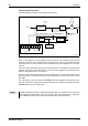
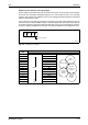
4.6.5 Interpolation
The interpolation mode is used to match the position control gains of the axes when performing
the interpolation operation of servo motors of two or more axes for an X-Y table or the like. In this
mode, the position control gain 1 and speed control gain 1 which determine command
trackability are set manually and the other gain adjusting parameters are set automatically.
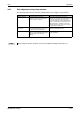
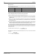
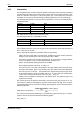
The following table provides an overview over the parameters, which are set automatically in
interpolation mode:
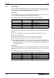
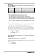
The following parameters are adjustable manually:
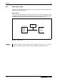
For interpolation between several axes the gain factor of the position control loop should be set
to the same value for all axes.
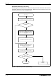
For the setting please follow the instructions which are given below:
Choose the auto tuning mode 1 (parameter No. 8: 0001) and set the machine resonance
frequency of the response level 1 of 15Hz (parameter No. 9: 0001)
Increase the response level selection (parameter No. 9), and return the setting if vibration
occurs. The optimum value is reached shortly before vibrations set in.
Choose the interpolation mode (parameter No. 8: 0000).
Set the highest possible value for pr. 13 and pr. 14.
The value set for pr. 13 in step d corresponds to the upper limiting value of the gain factor
for position control loop1. Set pr. 13 to the same value as that for the axis to be interpolated.
The value set for pr. 14 in step corresponds to the upper limiting value of the gain factor
for speed control loop1. Check the rotation and set pr. 14 of the axis to be interpolated to
a value that is at least three times the value set in step for pr. 13.
Looking at the interpolation characteristic and rotation status, fine-adjust the gains and
response level setting.
The response level of the position control loop is specified via the gain factor PG1 (pr. 13).
Increasing PG1 improves trackability to a position command but a too high value will make
overshooting liable to occur at the time of settling. The droop pulse value is determined by the
following expression:
The response level of speed control loop 1 is specified via the gain factor VG1 (pr. 14). For the
response level of the speed control loop the following applies:
Parameter Symbol Name
12 GD2 Ratio of load inertia moment to servo motor inertia moment
15 PG2 Position control gain 2
16 VG2 Speed control gain 2
17 VIC Speed intergral compensation
Tab. 4-21: Parameter adjusted for interpolation mode
Parameter Symbol Name
13 PG1 Position control gain 1
14 VG1 Speed control gain 1
Tab. 4-22: Parameter adjusted for manual mode
droop pulse value [pulsen]
rotation speed [r/min]
60
--------------------------------------------------------
131072 [pulse]×
PG1
------------------------------------------------------------------------------------------------------=
VG1 PG1 3×≥