
Instruction manual


Introduction Operating elements
1 - 14
S000512C
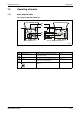
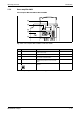
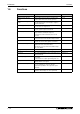
Fig. 1-18: Servo amplifier MR-J2S-350B or less
No. Name Description Reference
Bus cable connector (CN1A) Used to connect the servo system controller or
preceding axis servo amplifier.
Section 3.1.3
Bus cable connector (CN1B) Used to connect the subsequent axis servo
amplifier or termination connector (MR-A-TM)
Section 3.1.3
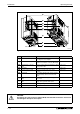
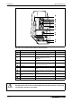
Communication connector
(CN3)
Used to connect a personal computer or output
analog monitor data.
Section 3.1.3
Name plate — Section 1.3.3
Encoder connector (CN2) Used for connection of the servo motor
encoder.
Section 3.1.3
Charge lamp Lit to indicate that the main circuit is charged.
While this lamp is lit, do not reconnect the
cables.
—
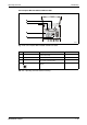
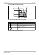
Main circuit terminal block
(TE1)
Used to connect the input power supply and
servo motor.
Section 3.1.2
Control circuit terminal block
(TE2)
Used to connect the control circuit power
supply and regenerative brake option.
Section 3.1.2
Protective earth terminal (PE) Module grounding Section 3.4
Fan — —
Tab. 1-2: Operating elements and their meaning
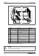
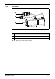
b
CAUTION:
Any mixing up of the connectors CN1A, CN1B, CN3 and CN2 can lead to a shortcircuit
and damage to the inputs and outputs.
MR-J2S-100B or less
MR-J2S-200B and MR-J2S-350B