
Specifications


13
MITSUBISHI ELECTRIC
2
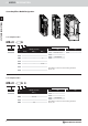
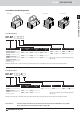
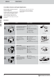
SERVO MOTORS
왎
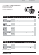
HF-KP (B) Series Servo Motor Specifications (200 V Type)
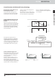
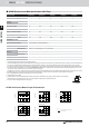
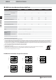
HF-KP Series Servo Motor Torque Characteristics
0 1000 2000 3000 4000 5000 6000
0.4
0.2
0.6
0 1000 2000 3000 4000 5000 6000
0.75
0.5
0.25
1.0
0 1000 2000 3000 4000 5000 6000
1.5
1.0
0.5
2.0
0 1000 2000 3000 4000 5000 6000
3.0
2.0
1.0
4.0
0 1000 2000 3000 4000 5000 6000
6.0
4.0
2.0
8.0
HF-KP053 (B) HF-KP13 (B)
HF-KP43 (B)
HF-KP73 (B)
HF-KP23 (B)
Notes:
1. : For 3-phase 200VAC or 1-phase 230VAC.
2. : For 1-phase 200VAC.
Torque [Nm]
Torque [Nm]
Torque [Nm]
Torque [Nm]
Torque [Nm]
Peak running range
Peak running range
Peak running range
Peak running
range
Peak running range
Continuousrunning range
Continuousrunning range
Continuousrunning range
Continuousrunning range
Continuousrunning range
Rotation speed [r/min]
Rotation speed [r/min]
Rotation speed [r/min]
Rotation speed [r/min]
Rotation speed [r/min]
Y
X
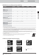
SERVO MOTORS SPECIFICATIONS ///
Servo motor model HF-KP053 (B)
HF-KP13 (B)
HF-KP23(B)
HF-KP43 (B)
HF-KP73(B)
Servo amplifier model MR-J3-10A/B/T
MR-J3-10A/B/T MR-J3-20A/B/T MR-J3-40A/B/T MR-J3-70A/B/T
Power facility capacity [kVA]
0.3
0.3 0.5 0.9 1.3
Continuous
characteristics
rated output [W]
50
100 200 400 750
rated torque [Nm]
0.16
0.32 0.64 1.3 2.4
Maximum torque [Nm] 0.48
0.95 1.9 3.8 7.2
Rated rotation speed [rpm] 3000
3000 3000 3000 3000
Maximum rotation speed [rpm] 6000
6000 6000 6000 6000
Permissible instantaneous rotation speed 6900
6900 6900 6900 6900
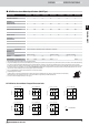
Power rate at continuous speed [kW/s] 4.87
11.5 16.9 38.6 39.9
Rated current [A] 0.9
0.8 1.4 2.7 5.2
Maximum current [A] 2.7
2.4 4.2 8.1 15.6
Moment of inertia
J[×10
-4
kg m
2
]
standard
0.052
0.088 0.24 0.42 1.43
with electromagnetic brake
0.054
0.090 0.31 0.50 1.63
Regeneration braking frequency [1/min] (a)
(b) 448 249 140
Recommended load/ motor inertia ratio
15
15 24 22 15
Speed/ position detector 18-bit encoder (resolution per encoder/servo motor rotation: 262144 p/rev.
Structure Totally enclosed, non-ventilated (protection rating: IP65)
Environment
ambient temperature
Operation: 0 – 40 °C (no freezing);Storage:-15–70°C(nofreezing)
ambient humidity
Operation: 80 % RH max. (no condensation); Storage: 90 % RH max. (no condensation)
atmosphere
Indoors (no direct sunlight); no corrosive gas, no inflammable gas, no oil mist, no dust
elevation/vibration
1000 m or less above sea level; X: 49 m/s² , Y: 49 m/s²
Weight [kg]
standard motor
0.35
0.56 0.94 1.5 2.9
Order information (without brake) Art. no.
161507
160211 161508 161509 161510
The power facility capacity varies depending on the power supply’s impedance.
The regenerative braking frequency shown is the permissible frequency for decelerating a stand-alone motor from rated rpm to a stop. When under load, however, the value becomes the table value divided by
(m+1) where m is the load inertia moment divided by the motor inertia moment. When the rated rpm is exceeded, the regenerative brake frequency is inversely proportional to the square of (operating
speed/rated speed). When the operating speed varies frequently or when regeneration is constant (as with vertical feeds), find the regeneration heat generated (W) while operating. The heat should not exceed
the tolerable regenerative power (W). Refer to the section "OPTIONS AND PERIPHERAL EQUIPMENT" in this catalog for details on the tolerable regenerative power (W). Optimal regenerative resistor varies for
each system. Select the most suitable regenerative resistor by using the capacity selection software.
(a)/(b) When a motor decelerates to a stop from the rated speed, the regenerative frequency will not be limited if the effective torque is within the rated torque range. When a motor decelerates to a stop from
the maximum speed, the regenerative frequency will not be limited if the load inertia moment is (a) 26-fold (b) 15-fold or less and the effective torque is within the rated torque range.
Please contact Mitsubishi if the load/motor of inertia moment ratio exceeds the value in the table
The shaft-through portion is excluded.
The vibration direction is shown in the right side diagram. The numeric value indicates the maximum value of the component (commonly the bracket on the antiload side).
Fretting of the bearing occurs easily when the motor stops, so please maintain vibration to approximately one-half the allowable value.
For servo motors with electromagnetic brake please refer to page 17.