
Specifications


3.WIRING
3– 24
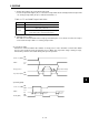
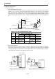
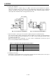
Fig. 3-7 Torque Control Level (RS1=ON)
Across
RS1-SG
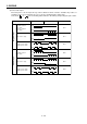
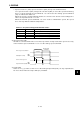
Table 3-4 Torque Generation Directions
Open
Short
Open
Short
+0.05
+8
-8
CCW direction
TC applied voltage [V]
Across
RS2-SG
Open
Open
Short
Short
Rotation Direction
Max. torque
(Note)
CCW direction
CW direction
-0.05
Max. torque (Note)
+ polarity
No torque
No torque
0V
No torque
– polarity
No torque
No torque
Forward
rotation
Reverse
rotation
Torque
Note: Set using parameter No. 26.
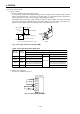
Analog torque command (TC)
CCW (forward rotation in driving mode/
reverse rotation in regenerative mode)
CW (reverse rotation in driving mode/
forward rotation in regenerative mode)
CW (reverse rotation in driving mode/
forward rotation in regenerative mode)
CCW (forward rotation in driving mode/
reverse rotation in regenerative mode)
(3) Torque control mode
1) Torque control
a. Torque command and generated torque
A relationship between the applied voltage of the analog torque command (TC) and the
torque generated by the servo motor is shown in Fig. 3-7. Generated torque limit values
will vary about 5% relative to the voltage depending on products.
Generated torque may vary at the voltage of -0.05V to +0.05V. Table 3-4 shows the torque
generation directions determined by the forward rotation selection (RS1) and reverse ro-
tation selection (RS2) when the analog torque command (TC) is used.
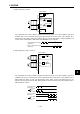
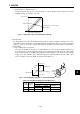
SG
-8V to +8V
Fig. 3-8 Connection Example
Servo amplifier
SD
LG
TC
RS2
RS1
b. Connection diagram
Connect as shown in Fig. 3-8.