
Specifications


3.WIRING
3– 28
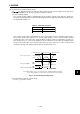
3) Speed setting in speed control mode
a. Speed command and speed
The servo motor is run at the speed set in parameter No. 8 (internal speed command 1) or
at the speed set in the applied voltage of the analog speed command (VC). A relationship
between analog speed command (VC) applied voltage and servo motor speed and the
rotation directions determined by the forward rotation start signal (ST1) and reverse rota-
tion start signal (ST2) are as in 1)a, (2) in this section.
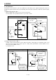
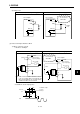
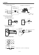
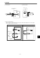
b. Connection diagram
Generally connect as shown in Fig. 3-14. When a precision speed command is required,
refer to 1)b, (2) in this section.
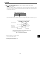
c. Speed selection 1 (SP1) and speed command value
Use speed selection 1 (SP1) to select between the speed set to the internal speed com-
mand 1 and the speed set to the analog speed command (VC) as indicated in Table 3-8.
When the speed is changed during rotation, it is increased or decreased according to the
value set in parameter No. 11 or 12.
When the internal speed command 1 is used to command the speed, the speed does not
vary with the ambient temperature.
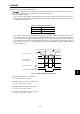
d. Speed reached (SA)
As in 2), (2) in this section.
4) Torque limit in torque control mode
As in 2), (3) in this section.
Speed Command ValueAcross SP1-SG
Open
Short
Table 3-8 SP1 and Speed Command Value
Analog speed command (VC)
Internal speed command 1 (parameter No. 8)
SG
P15R
VC
LG
SD
Fig. 3-14 Connection Example
2kΩ
2kΩ
Japan Resistor
RRS10 or equivalent
Servo amplifier
SP1