
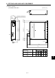
Specifications


6– 4
6. OPTIONS AND AUXILIARY EQUIPMENT
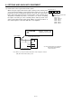
Servo amplifier
Regenerative brake option
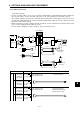
Note: Make up a sequence which will switch off the magnetic contactor
(MC) when abnormal heating occurs.
(Note)
5m (16.4 ft) max.
G3 • G4: Thermal protector terminals.
Abnormal heating will dis-
connect G3-G4.
D
P
P
C
G3
G4
C
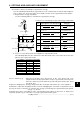
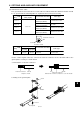
(3) Connection of the regenerative brake option
When using the regenerative brake option, always remove wiring from
across P-D and install the regenerative brake option across P-C. Set
parameter No.0 according to the option to be used. The regenerative
brake option will generate heat of about 100°C. Fully examine heat
dissipation, installation position, used cables, etc. before installing
the option. For wiring, use fire-retarding cables and keep them clear
of the regenerative brake option body. Always use twisted cables of
max. 5m length for connection with the servo amplifier.
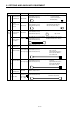
Always remove the
lead from across P-D.
CAUTION
Parameter No. 0
Selection of regenerativ
e
brake option
0: Not used.
2: MR – RB 032
3: MR – RB 12
4: MR – RB 32
5: MR – RB 30
6: MR – RB 50