
Specifications


6– 9
6
6. OPTIONS AND AUXILIARY EQUIPMENT
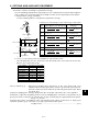
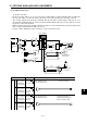
(2) Standard encoder cable
The specifications and connection of each cable are indicated below. A fabricated cable should
be as specified in the following table or equivalent and connected correctly.
Core Size
[mm
2
]
Core Insulation Sheath OD
(Note) d [mm]
0.9 to 1.27
Recommended Cable Model
UL20276
AWG28 7pair (BLACK)
UL20276
AWG28 10pair (BLACK)
UL20276
AWG24 7pair (BLACK)
UL20276
AWG22 7pair (BLACK)
Standard encoder cable
Communication cable
Bus cable
Standard encoder cable
Standard encoder cable
Cable Type
Note: d is as shown below.
x Pair
0.08 x 7
0.08 x 10
0.2 x 7
0.3 x 7
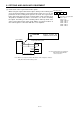
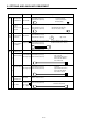
b. Fitting of the ground plate
Conductor
Sectional view of cor
Insulation sheath
d
For the control signal connector, connect the external conductor of the shielded cable to the
ground plate securely as shown below.
a. Termination of external conductor
External conductor Sheath
External conductor
Pull back the external conductor to cover the sheath
SheathCore
Strip the sheath.
Screw
Screw
Ground plate
Cable
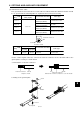
Characteristics of One Core
Recommended Cable Model
(Note)
A14B2343
Flexing, long-life
encoder cable
Cable Type
Note: Junkosha make, purchased from Toa Electric
0.2 x 6
40/0.08 105 max.
Structure
[pcs./mm]
Conductor
resistance[Ω/km]
Core Size
[mm
2
]
x Pair