
Specifications


8. TROUBLESHOOTING
8– 2
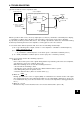
Excessive adjustment or change of parameter setting must not be made as it will
make operation instable.
8-1 Troubleshooting at start-up
The following faults may occur at start-up. If any of such faults occurs, take the corresponding
action.
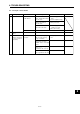
8-1-1 Position control mode
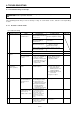
(1) Troubleshooting
CAUTION
No. Start-Up Sequence Fault Investigation Possible Cause Refer To
1 Power on • LED is not lit.
• LED flickers.
Not improved if connectors
CN1A, CN1B and CN2 are
disconnected.
1) Power supply voltage fault
2) Servo amplifier is faulty.
Improved when connectors
CN1A and CN1B are
disconnected.
Power supply of CN1 cabling
is shorted.
Improved when connector
CN2 is disconnected.
1) Power supply of encoder
cabling is shorted.
2) Encoder is faulty.
Alarm occurs. Refer to Section 8-2 and remove cause.
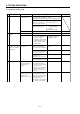
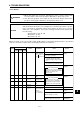
Alarm occurs. Refer to Section 8-2 and remove cause.2 Switch on servo-on
signal.
Section 8-2
Section 8-2
Servo motor shaft is
not servo-locked
(is free).
1. Check the display to see
if the servo amplifier is
ready to operate.
2. Check the external I/O
signal indication to see
if the servo-on (SON)
signal is ON.
1) Servo on signal is not
input. (Wiring mistake)
2) 24VDC power is not
supplied to COM.
Servo motor does not
rotate.
Check cumulative
command pulses.
3 Enter input
command.
(Test operation)
Section 2-3-2
1) Wiring mistake
(a) For open collector
pulse train input,
24VDC power is not
supplied to OPC.
(b) LSP/LSN-SG are not
connected.
2) No pulse is input.
(1), Section 2-3-3
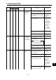
Rotational ripples
(speed fluctuations)
are large at low
speed.
Make gain adjustment in
the following procedure:
1) Increase the auto
tuning response level.
2) Repeat acceleration
and deceleration
several times to
complete auto tuning.
4 Gain adjustment Section 2-4Gain adjustment fault
Large load inertia
moment causes the
servo motor to
oscillate side to side.
Make gain adjustment in
the following procedure:
If the servo motor may
be run with safety,
repeat acceleration and
deceleration several
times to complete auto
tuning.
Section 2-4Gain adjustment fault
Position shift occurs.
(2) in this section
Pulse counting error, etc.
due to noise.
5 Cyclic operation
Improved when connector
CN3 is disconnected.
Power supply is shorted.
Confirm the cumulative
command pulses, cumulative
feedback pulses and actual
servo motor position.