
Specifications


10– 86
10. SPECIFICATIONS
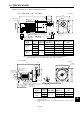
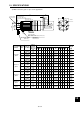
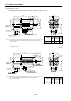
HA – FF33(B)G1 • HA – FF43(B)G1
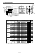
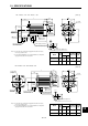
HA – FF63(B)G1
[Unit: in]
Servo Motor
Model
HA–FF33
(B)G1
HA–FF43
(B)G1
Reduction
Gear
Model
GR–S–30
GR–S–40
(Note 2)
Reduction
Ratio
1/5
1/10
1/30
1/5
1/10
1/30
Inertia Moment
WK
2
[oz•in
2
]
(Note 1) Variable
Dimensions
LL
9.84 (11.3)
9.84 (11.3)
9.84 (11.3)
10.2 (11.63)
10.2 (11.63)
10.2 (11.63)
2.980 (3.704)
2.980 (3.704)
2.939 (3.663)
5.577 (7.490)
5.577 (7.490)
5.536 (7.449)
14.3 (15.9)
14.3 (15.9)
14.3 (15.9)
17.6 (19.6)
17.6 (19.6)
17.6 (19.6)
(Note 1) Weight
[lb]
Note: 1. Values in parentheses are those for the servo motors with electromagnetic brakes.
Note: 2. Nominal reduction ratios. For actual reduction ratios, refer to Section 10-3.
[Unit: in]
Servo Motor
Model
HA–FF63
(B)G1
Reduction
Gear
Model
GR–S–60
(Note 2)
Reduction
Ratio
1/5
1/10
1/30
Inertia Moment
WK
2
[oz•in
2
]
7.326 (9.240)
7.326 (9.240)
7.217 (9.131)
28.7 (30.6)
28.7 (30.6)
28.7 (30.6)
(Note 1) Weight
[lb]
Note: 1. Values in parentheses are those for the servo motors with
Note: 1. electromagnetic brakes.
Note: 2. Nominal reduction ratios. For actual reduction ratios, refer to
Note: 1. Section 10-3.
Bottom
Top
ø1.85
1.54
0.71
Caution plate
Earth terminal M3 screw
(Opposite side)
Earth terminal M3 screw
(Opposite side)
Top Bottom
Motor plate
LL
1.48
1.1
A
A
0.98
0.47 0.12
ø5.12
ø0.75
0.24
Section AA
0.24
0.14
M6 screw,
depth 0.39
M6 screw,
depth 0.47
45°
5.71
4–ø0.39
ø7.09
2.853.49
6.3
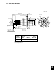
ø1.85
1.54
Caution plate
Top
Bottom
Motor plate
10.81(12.26)
1.83
0.12
1.42
1.26
A
A
0.47
0.79
ø6.69
ø0.87
0.24
0.14
0.24
Section AA
45°
7.28
4–ø0.47
3.643.94
7.58
ø8.86
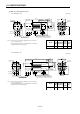
Encoder cable 11.8in
With connector 172169-9
(AMP make)
Power supply cable
VCTF 3-0.05
2
19.7in
(With end-insulated round crimping terminal 0.05-4)
Red: Phase U
White: Phase V
Black: Phase W
Top
Bottom
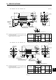
Encoder cable 11.8in
With connector 172169-9
(AMP make)
Power supply cable
VCTF 3-0.05
2
19.7in
(With end-insulated round crimping terminal 0.05-4)
Red: Phase U
White: Phase V
Black: Phase W