
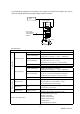
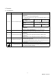
Specifications

5
BCN-B11127-479*
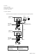
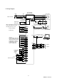
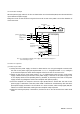
2. Wiring Diagram
Emergency stop
Proximity dog
Zeroing completion
Monitor output 1
RA2
RA3
RA4
RA5
Rough match
In position
Trouble
Ready
External torque limit
16
15
17
7
5
14
8
9
10
SON
LSN
LSP
MD0
DI0
DI1
ST1
ST2
SG
20
SG
2
11
1
12
P15R
LG
TLA
VC
Plate
SD
CN1B
10
8
DOG
SG
CN1
A
18
ZP
4
13
6
18
19
CPO
INP
ALM
RD
COM
3
VDD
13
3
Plate
LG
SD
CN3
LG
4
MO1
14
MO2
A
A
C
D
P
B1
W
(Black)
V
(White)
U
(Red)
(Green)
Electromagnetic
brake
Encoder
Encoder cable
(Available as option or to be fabricated)
NFB
MC
Regenerative
brake option
L12
L11
L
3
L
2
L1
10
k
2m(78.74inch) max.
Upper limit setting
W
V
U
Servo amplifier
MR-J2S-A-S061
9
RA
1
20
SG
Communication cable
(Available as option or to be fabricated)
CN3
TE1
TE2
When connecting the external regenerative
brake option, always disconnec
t
the jumpe
r
from across P-D.
SM
COM
CN
2
Servo motor
Servo on
Forward rotation stroke end
Reverse rotation stroke end
Automatic/manual selection
Point table No. selection 1
Point table No. selection 2
Forward rotation start
Reverse rotation star
t
3-phase 200VAC
10m(39.37inch) max.
10m
(39.37inch) max.
Upper limit setting
To be shut off when servo on signal
switches off
or alarm occurs.
Monitor output 2
B2
10
k