
Installation manual


5
Indoor terminal block
Indoor/outdoor unit
connecting wire (A)
Outdoor terminal block
Earth wire
(green/yellow)
• Make earth wire a little longer than others. (More than 55 mm)
• For future servicing, give extra length to the connecting wires.
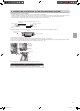
2-6. CONNECTING WIRES FOR INDOOR UNIT
You can connect indoor/outdoor lead wire without removing the front
grille.
1) Open the front grille.
2) Remove panel.
3) Remove electrical cover.
4) Remove cord clamp.
5) Pass indoor/outdoor unit connecting wire (A) from the back of the
indoor unit and process the end of the wire.
6) Loosen terminal screw, and connect first the earth wire, then
indoor/outdoor unit connecting wire (A) to the terminal block. Be
careful not to make mis-wiring. Fix the wire to the terminal block
securely so that no part of its core is appeared, and no external
force is conveyed to the connecting section of the terminal block.
7) Firmly tighten the terminal screws to prevent them from loosening.
After tightening, pullthe wires lightly toconrm that they do not
move.
8) Secure indoor/outdoor unit connecting wire (A) and the earth wire
with the cord clamp. Never fail to hook the left claw of the cord
clamp. Attach the cord clamp securely.
Lead wire
Terminal block
Fixing screw
Indoor/outdoor unit
connecting wire (A)
Electrical cover
Cord clamp
35 mm
15 mm
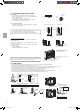
2-5. EMBEDDING THE INDOOR UNIT IN A
WALL
• When installing a grating, use a grating with narrow upper and lower
horizontalbarssothattheairowfromtheupperandlowerairout-
lets does not contact the bars. If the horizontal bars will block the
lower air outlet, use a stand, etc., to adjust the height of the indoor
unit. If the upper or lower air outlet is blocked, the air conditioner will
not be able to cool or warm the room well.
• Do not block the receiver with the grating. Otherwise, the grating will
interferewiththeremotecontrollersignalandsignicantlyreducethe
distance and area (angle) from which the signals can be received.
• Use a grating with vertical bars, etc., that has at least 75% open
area. If the grating has horizontal bars or if the open area is less
than 75%, performance could be reduced.
• When the indoor unit is embedded in a wall (built-in), the time it
takes for the room temperature to reach the set temperature will in
-
crease.
100 or more
Upper air outlet
Lower air outlet
Receiver
Grating
Indoor
unit
100 or more
25 - 35
100 or
more
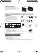
EMBEDDED INDOOR UNIT SETTING (MUST BE PERFORMED)
• When embedding the indoor unit in a wall, restrict the movement of
the horizontal vane for the upper air outlet so that it only operates
horizontally.
• If this setting is not performed, heat will build up in the wall and the
room will not be cooled or warmed properly.
• Cut the wires on the left and right sides of JRFBL using a pair of nip-
pers, etc., as shown below.
Cut the wires on both ends.
Cut
Control board
2-4. INDOOR UNIT INSTALLATION
• Hook the top of the indoor unit on the indoor unit mounting bracket (7).
• Use the included wood screws (9) and washer (10), and fasten the
indoor unit at 2 locations(
) each at the top and the middle of the
unit.
Cut the JRFBL wires.
JRFBL
JR24
JG79A144H05.indd 5 2011/06/22 16:01:23