Revision A: • 3. SPECIFICATION and 4. OUTLINES AND DIMENSIONS have been modified. Please void OBH752. INDOOR UNIT No. OBH752 REVISED EDITION-A SERVICE MANUAL Models MFZ-KJ09NA MFZ-KJ12NA MFZ-KJ15NA MFZ-KJ18NA - U1 - U1 - U1 - U1 Outdoor unit service manual MUFZ-KJ•NAHZ Series (OBH753) MXZ-C•NA, MXZ-C•NAHZ Series (OBH702, OCH573) CONTENTS 1. TECHNICAL CHANGES ··································· 3 2. PART NAMES AND FUNCTIONS ····················· 4 3.
Use the specified refrigerant only Never use any refrigerant other than that specified. Doing so may cause a burst, an explosion, or fire when the unit is being used, serviced, or disposed of. Correct refrigerant is specified in the manuals and on the spec labels provided with our products. We will not be held responsible for mechanical failure, system malfunction, unit breakdown or accidents caused by failure to follow the instructions. Revision A: • 3. SPECIFICATION and 4.
1 TECHNICAL CHANGES MFZ-KJ09NA- U1 MFZ-KJ12NA- U1 MFZ-KJ15NA- U1 MFZ-KJ18NA- U1 1.
2 PART NAMES AND FUNCTIONS MFZ-KJ09NA MFZ-KJ12NA MFZ-KJ15NA MFZ-KJ18NA Air outlet Horizontal vane 0XOWL ÀRZ YDQH Vertical vane Fan guard $LU FOHDQLQJ ¿OWHU (Anti-allergy enzyme filter, option) Panel Front panel $LU ¿OWHU 1DQR SODWLQXP ¿OWHU Display and operation section (When the front panel is opened) E.
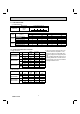
3 SPECIFICATION 1. Single connection Indoor model Power supply V, phase, Hz Max. fuse size (time delay)/ Disconnect switch A MFZ-KJ09NA MFZ-KJ12NA MFZ-KJ15NA 208/230, 1, 60 15 MFZ-KJ18NA 20 Airflow Super High - High - Med. Low - Quiet COOL Dry CFM (Wet) 417 - 360 - 272 - 198 - 138 (354 - 306 - 231 - 168 - 117) HEAT Dry CFM 417 - 328 - 254 - 191 - 138 470 - 399 - 328 - 268 - 212 Sound level Super High - High - Med. Low - Quiet Cond. drain connection O.D.
3-1. OPERATING RANGE (1) POWER SUPPLY Rated voltage Guaranteed voltage (V) 208/230 V 1 phase 60 Hz Indoor unit Min. 187 208 230 Max. 253 (2) OPERATION Intake air temperature (°F) Mode Condition Indoor DB 80 90 67 Standard temperature Maximum temperature Cooling Minimum temperature Maximum humidity Standard temperature Heating Maximum temperature Minimum temperature Outdoor WB 67 73 57 DB 95 115 14 60 67 60 47 75 -13 78% 70 80 70 WB — — — — 43 65 -14 3-2. OUTLET AIR SPEED AND COVERAGE 1.
4 OUTLINES AND DIMENSIONS MFZ-KJ09NA MFZ-KJ12NA MFZ-KJ15NA MFZ-KJ18NA OBH752A 7 Unit: inch
5 WIRING DIAGRAM MFZ-KJ09NA MFZ-KJ12NA MFZ-KJ15NA MFZ-KJ18NA OBH752A 8
6 REFRIGERANT SYSTEM DIAGRAM MFZ-KJ09NA MFZ-KJ12NA MFZ-KJ15NA MFZ-KJ18NA Refrigerant pipe 3/8 ( 9.52) (MFZ-KJ09/12) 1/2 ( 12.7) (MFZ-KJ15/18) (with heat insulator) Indoor heat exchanger Distributor Flared connection Indoor coil thermistor RT12, RT14, RT15 (main) RT13 (sub) Room temperature thermistor RT11 Flared connection Refrigerant flow in cooling Refrigerant flow in heating OBH752A Refrigerant pipe 1/4 ( 6.
7 SERVICE FUNCTIONS MFZ-KJ09NA MFZ-KJ12NA MFZ-KJ15NA MFZ-KJ18NA 7-1. TIMER SHORT MODE • For service, the following set time can be shortened by bridging the timer short mode point on the electronic control P.C. board. (Refer to 9-7.) • The set time for the ON/OFF timer can be reduced to 1 second for each minute. • After the breaker is turned on, the time for starting the compressor, which normally takes 3 minutes, can be reduced to 3 seconds.
7-3. AUTO RESTART FUNCTION When the indoor unit is controlled with the remote controller, the operation mode, the set temperature, and the fan speed are memorized by the indoor electronic control P.C. board. “AUTO RESTART FUNCTION” automatically starts operation in the same mode just before the shutoff of the main power. Operation If the main power has been cut, the operation settings remain. After the power is restored, the unit restarts automatically according to the memory.
8 MICROPROCESSOR CONTROL MFZ-KJ09NA MFZ-KJ12NA MFZ-KJ15NA MFZ-KJ18NA WIRELESS REMOTE CONTROLLER Signal transmitting section Distance of signal : About 20 ft. (6 m) Beep(s) is (are) heard from the indoor unit when the signal is received.
8-1. COOL ( ) OPERATION (1) Press STOP/OPERATE (OFF/ON) button. OPERATION INDICATOR lamp of the indoor unit turns on with a beep tone. (2) Select COOL mode with OPERATION SELECT button. (3) Press TEMPERATURE buttons TEMP or button to select the desired temperature. The setting range is 61 - 88°F (16 - 31°C). 1. Coil frost prevention The compressor operational frequency is controlled by the temperature of the indoor heat exchanger to prevent the coil from frosting.
8-5. AUTO CHANGE OVER ··· AUTO MODE OPERATION Once desired temperature is set, unit operation is switched automatically between COOL and HEAT operation. 1. Mode selection (1) Initial mode At first indoor unit operates only indoor fan with outdoor unit OFF for 3 minutes to detect present room temperature. Following the conditions below, operation mode is selected. If the room temperature thermistor RT11 reads more than set temperature, COOL mode is selected.
The multi-flow vane is automatically set to the appropriate position. In HEAT, the multi-flow vane automatically changes its position according to the indoor fan speed. Even if 2 FLOW is selected, air will blow only from the top of the unit in the following conditions: • During COOL/DRY: The room temperature is close to set temperature. The air conditioner has operated for 0.5 to 1 hour. • During HEAT: The air flow temperature is low. (During defrosting operation, start of operation, etc.
(11) POWERFUL ( ) operation The air conditioner automatically adjusts the fan speed and the set temperature, and operates the POWERFUL mode. The POWERFUL mode is cancelled automatically 15 minutes after operation starts, or when POWERFUL button is pressed once again within 15 minutes after operation starts. The operation mode returns to the mode prior to POWERFUL operation.
8-8. WEEKLY TIMER OPERATION • A maximum of 4 ON or OFF timers can be set for individual days of the week. • A maximum of 28 ON or OFF timers can be set for a week. E.g. : Runs at 75°F (24°C) from waking up to leaving home, and runs at 81°F (27°C) from getting home to going to bed on weekdays. Runs at 81°F (27°C) from waking up late to going bed early on weekends.
button to complete and transmit the weekly timer setting. (4) Press * which was blinking goes out, and the current time will be displayed. NOTE: button to transmit the setting information of weekly timer to the indoor unit. Point the remote controller toward the • Press indoor unit for 3 seconds. • When setting the timer for more than one day of the week or one number, button once after all the settings are complete. All the weekly timer settings will be saved. setting.
Set temperature for SLEEP operation. For about 30 minutes after SLEEP ( ) button is pressed, the set temperature remains as set for the operation running when the SLEEP button is pressed. It will change to the set temperature for SLEEP operation in about 30 minutes. Pressing SLEEP ( ) button again returns the operation to the previous settings. is pressed. Set temperature for the operation before SLEEP operation is pressed.
8-11. EMERGENCY/TEST OPERATION In the case of test run operation or emergency operation, use EMERGENCY OPERATION switch on the right side of the indoor unit. Emergency operation is available when the remote controller is missing or has failed, or when the batteries in the remote controller are running down. The unit will start and OPERATION INDICATOR lamp will light up. The first 30 minutes of operation is the test run operation. This operation is for servicing.
9 TROUBLESHOOTING MFZ-KJ09NA MFZ-KJ12NA MFZ-KJ15NA MFZ-KJ18NA 9-1. CAUTIONS ON TROUBLESHOOTING 1. Before troubleshooting, check the following 1) Check the power supply voltage. 2) Check the indoor/outdoor connecting wire for miswiring. 2. Take care of the following during servicing 1) Before servicing the air conditioner, be sure to turn OFF the main unit first with the remote controller, and then after confirming the horizontal vane is closed, turn OFF the breaker.
5. Description of multi system air conditioner OUTDOOR UNIT: MXZ series The multi system outdoor unit can be connected to 2 or more indoor units. • The units do not operate and the operation indicator lamp flashes as shown in the figure below when the total capacity of the indoor units exceed the capacity of the outdoor unit. Do not connect the indoor units beyond the outdoor unit capacity.
9-2. FAILURE MODE RECALL FUNCTION Outline of the function This air conditioner can memorize the abnormal condition which has occurred once. Even though OPERATION INDICATOR lamp indication listed on the troubleshooting check table (9-4.) disappears, the memorized failure details can be recalled. This mode is very useful when the unit needs to be repaired for the abnormality which does not recur. 1.
2. Indoor unit failure mode table NOTE: Blinking patterns of this mode differs from the ones of Troubleshooting check table (9-4.). Left lamp of Right lamp of OPERATION OPERATION INDICATOR lamp INDICATOR lamp Abnormal point (Failure mode) Condition Remedy Not lighted Not lighted 1-time flash every 0.5-second Not lighted Room temperature thermistor The room temperature thermistor short or open circuit is detected every 8 seconds during operation.
9-3. INSTRUCTION OF TROUBLESHOOTING Start Indoor unit operates. Outdoor unit does not operate. Outdoor unit operates only in Test Run operation. Check room temperature thermistor. Refer to 9-7. "Test point diagram and voltage". Indoor unit operates. Outdoor unit does not operate normally. Outdoor unit does not operate even in Test Run operation. Unit does not operate normal operation in COOL or HEAT mode. Indoor unit operates, when EMERGENCY OPERATION switch is pressed.
9-4. TROUBLESHOOTING CHECK TABLE Before taking measures, make sure that the symptom reappears for accurate troubleshooting. When the indoor unit has started operation and detected an abnormality of the following condition (the first detection after the power ON), the indoor fan motor turns OFF and OPERATION INDICATOR lamp flashes. OPERATION INDICATOR Lighted Blinking Not lighted No. Abnormal point 1 Miswiring or serial signal Operation indicator lamp Left lamp flashes. 0.
OPERATION INDICATOR Lighted Blinking Not lighted No. Abnormal point 1 MXZ type Operation mode setting Operation indicator lamp Right lamp flash 2.5-second OFF Symptom Condition Remedy Outdoor unit operates but indoor unit does not operate. When the operation mode of the each indoor unit is differently set to COOL (includes DRY) and HEAT at the same time, the operation mode of the indoor unit that has operated first has the priority. • Select the same operation mode for all the units.
9-6. TROUBLESHOOTING FLOW A Check of indoor fan motor The indoor fan motor error has occurred, and the indoor fan does not operate. Turn OFF the power supply. Pay enough attention to the high voltage on the fan motor connector. Is there any foreign matter that interferes the rotation of the line flow fan? No Yes Remove the foreign matter and adjust the line flow fan.
B Check of remote controller, display receiver P.C. board and indoor control P.C. board Check if the remote controller is exclusive for this air conditioner. Press STOP/OPERATE (OFF/ON) button on the remote controller. Is LCD display on the remote controller visible? Yes No (Not clear) 1 Look at the image of the signal transmitting section of the remote controller through the monitor of a digital camera or a camera phone.
C Check of indoor electronic control P.C. board and indoor fan motor Turn OFF the power supply. Remove indoor fan motor connector CN211 and vane motor connector CN151 from the indoor electronic control P.C. board and turn ON the power supply. Does the unit operate with the remote controller? Does OPERATION INDICATOR lamp light up by pressing EMERGENCY OPERATION switch? No Yes Measure the resistance of indoor fan motor. Refer to 9-5. Short circuit: Replace the indoor fan motor.
D How to check miswiring and serial signal error MUFZ Type Turn OFF the power supply. Is there rated voltage in the power supply? Yes Check the power supply. No Turn ON the power supply. Is there rated voltage between the outdoor terminal block S1 and S2? Yes No Check the wiring. Press EMERGENCY OPERATION switch once.
MXZ Type Turn OFF the power supply. Is there rated voltage in the power supply? Yes Check the power supply. No Turn ON the power supply. Is there rated voltage between outdoor terminal block S1 and S2? Yes No Check the wiring. Press EMERGENCY OPERATION switch once.
LED indication for communication status C Turn ON the power supply. Communication status is indicated by the LED. Unit status Blinking: normal communication Lighting: abnormal communication or not connected Pattern 1 and 2 is repeatedly displayed alternately. Each pattern is displayed for 15 seconds. NOTE: "Lighting" in the table below does not indicate abnormal communication. Outdoor control P.C.
E Electromagnetic noise enters into TV sets or radios Is the unit grounded? Yes Is the distance between the antennas and the indoor unit within 9.91 ft. (3m), or is the distance between the antennas and the outdoor unit within 9.91 ft. (3m)? No Ground the unit. No Extend the distance between the antennas and the indoor unit, and/or the antennas and the outdoor unit. Yes Is the distance between the TV sets or radios and the indoor unit within 3.28 ft.
9-7. TEST POINT DIAGRAM AND VOLTAGE MFZ-KJ09NA MFZ-KJ12NA MFZ-KJ15NA MFZ-KJ18NA Indoor electronic control P.C. board FUSE (F11) T3.15AL250V Varistor (NR11) Serial signal input (CN202) JR05 JR06 Power supply (CN201) input 208/230 VAC ) Modification point for individual operation (Refer to 7-2.) To disable "Auto restart function", cut the Jumper wire to JR77. (Refer to 7-3.
10 DISASSEMBLY INSTRUCTIONS <"Terminal with locking mechanism" Detaching points> The terminal which has the locking mechanism can be detached as shown below. There are 2 types (refer to (1) and (2)) of the terminal with locking mechanism. The terminal without locking mechanism can be detached by pulling it out. Check the shape of the terminal before detaching. (1) Slide the sleeve and check if there is a locking lever or not. (2) The terminal with this connector has the locking mechanism.
OPERATING PROCEDURE PHOTOS 3. Removing the electronic control P.C. board and the display receiver P.C. board Photo 4 (1) Remove the panel. (Refer to 1.) (2) Remove the electrical box. (Refer to 2.) (3) Remove the earth wire connected to the electronic control P.C. board. (4) Disconnect all the connectors on the electronic control P.C. board. (5) Pull out the electronic control P.C. board from the electrical box. (6) Disengage the catches on the lead guide. (7) Disengage the display receiver P.C.
How to remove the multi-flow vane and the horizontal vanes Horizontal vane (back) Horizontal vane (front) Unit body (1) Removing the horizontal vane (front/back) (1)-1. See the figure below and push to open the indicated places on the horizontal vanes (between front and back) with your fingers so that you can access 4 vane shafts positioned on the back of the horizontal vanes. (vane shafts on each horizontal vane) Multi-flow vane (2) Removing the multi-flow vane (2)-1.
OPERATING PROCEDURE 5. Removing the horizontal vane motor PHOTOS Photo 9 Screws of the nozzle (1) Remove the panel. (Refer to 1.) (2) Remove the screws of the horizontal vane motor support and pull out the horizontal vane motor support from the nozzle. (3) Remove the screws of the horizontal vane motors. (4) Remove the horizontal vane motors from the horizontal vane motor support. (5) Disconnect the connectors from the horizontal vane motor.
OPERATING PROCEDURE PHOTOS 7. Removing the line flow fan and the indoor fan motor Photo 13 Screw of the line flow fan (1) Remove the panel. (Refer to 1.) (2) Remove the electrical box. (Refer to 2.) (3) Remove the nozzle. (Refer to 4.) (4) Disengage the water cover from the catches. (Photo 9) (5) Remove the screws fixing the motor bed. (6) Loosen the screw fixing the line flow fan. (7) Remove the motor bed together with the indoor fan motor and the motor band.
OBH752A 41
HEAD OFFICE: TOKYO BLDG., 2-7-3, MARUNOUCHI, CHIYODA-KU, TOKYO 100-8310, JAPAN © Copyright 2016 MITSUBISHI ELECTRIC CORPORATION Distributed in Mar. 2016. No. OBH752 REVISED EDITION-A Distributed in Feb. 2016. No. OBH752 Made in Japan New publication, effective Mar. 2016 Specifications are subject to change without notice.