
Wiring Diagram – Component Lacations
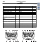


SENSOR
COMPONENT LOCATIONS
70-2
SENSOR
M1701000601151
Name Symbol Name Symbol
A/C pressure sensor A Interior temperature sensor <Automatic
A/C>
R
Accelerator pedal position sensor S Line pressure sensor <CVT> H
Air flow sensor (incorporating intake air
temperature sensor) <4G15>
G Manifold absolute pressure sensor
<4A91>
K
Air thermo sensor Q Oxygen sensor (front) C, J
Ambient temperature sensor L Oxygen sensor (rear) X
Camshaft position sensor F Photo sensor <Automatic A/C> O
Crank angle sensor I Primary pressure sensor <CVT> V
CVT control solenoid valve
(incorporating CVT fluid temperature
sensor)
M Primary speed sensor <CVT> H
Detonation sensor B, I Rear wheel speed sensor Z
Electronic control throttle valve
(incorporating throttle position sensor)
D, K Secondary speed sensor <CVT> H
Engine coolant temperature sensor E Side impact sensor Y
Front impact sensor N Steering wheel sensor <ASC> P
G and yaw rate sensor <ASC> U Torque sensor (for EPS) T
Front wheel speed sensor W Turbine speed sensor <CVT> H
AC402858
AK
<4A91>
<4G15>
A
A
B
D
F
G
H
K
L
L
M
M
N
N
C
E
E
J
F
H
I
I
*
*
Main
Index
Group
TOC