
Wiring Diagram – Configuration Diagrams
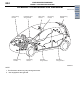
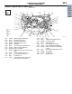
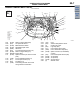
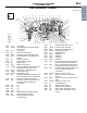

ENGINE COMPARTMENT
CONFIGURATION DIAGRAMS
80-8
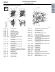
ENGINE COMPARTMENT <4G15> (CONTINUED)
AC600829
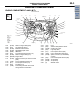
Control wiring
harness
Front wiring
harness
Earth cable
Battery wiring
harness
Connector
symbol
-101
thru
-138
A
Connector colour
code
B : Black
BR : Brown
DG: Dark grey
G : Green
GR : Grey
L : Blue
None : Milk white
O : Orange
R : Red
V : Violet
Y : Yellow
A-105A-136A-103A-102
A-101
A-104
A-122
A-133
A-135
A-132
A-129
A-130
A-131
A-128 A-126A-127
Y
AC
A-138
A-111
A-110
A-107A-108
A-114
A-124
A-125
A-121
A-137
A-123
8
7
9
16
2
Y
17
18
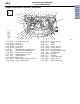
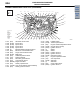
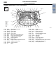
A-101 (2-B) Oil feeder control valve
A-102 (2-GR) Injector No.1
A-103 (2-GR) Injector No.2
A-104 (2-GR) Injector No.3
A-105 (2-GR) Injector No.4
A-107 (6-B) Electronic control throttle valve
A-108 (2-B) Purge control solenoid valve
A-110 (3-B) Camshaft position sensor
A-111 (1-B) Noise condenser
A-114 (66-GR) Engine-ECU
A-121 (2-B) Engine coolant temperature sensor
A-122 (4-GR) Oxygen sensor (Front)
A-123 (3-DG) Ignition coil No.4
A-124 (1) Starter
A-125 (1-B) Starter
A-126 (3-DG) Ignition coil No.3
A-127 (3-DG) Ignition coil No.2
A-128 (2) Detonation sensor
A-129 (1-L) Engine oil pressure switch
A-130 (1-B) A/C compressor
A-131 (4-GR) Alternator
A-132 (1) Alternator
A-133 (3-DG) Crank angle sensor
A-135 (3-DG) Ignition coil No.1
A-136 (2-B) Fuel pressure control solenoid valve
A-137 (2-GR) Wastegate solenoid valve
A-138 (2-B) Back-up lamp switch
Main
Index
Group
TOC