2PS24_28(NAFTA)_Cover2.fm 1 ページ 2010年8月27日 金曜日 午前11時44分 Introduction N09200100862 Thank you for buying a MITSUBISHI ECLIPSE/ECLIPSE SPYDER. We are confident you will enjoy your vehicle. It has been engineered for optimum performance, durability and comfort. By thoroughly reading this Owner’s Manual, you will gain an understanding of the many features that are included in the ECLIPSE/ECLIPSE SPYDER.
BK0132701US.
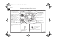
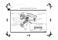
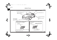
BK0132701US.book 1 ページ 2010年12月6日 月曜日 午後2時3分 Overview Instruments and controls (Driver’s area) N00100201114 Instrument cluster P.3-104 Combination headlights and dimmer switch P.3-125 Turn signal lever P.3-129 Steering wheel audio remote control switch (if so equipped) P.5-65 Supplemental restraint system - air bag (for driver’s seat) P.2-36 Horn switch P.3-136 Wiper and washer switch P.3-132 Ignition switch P.3-60 Electric remote-controlled outside mirror switch P.
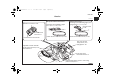
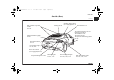
BK0132701US.book 2 ページ 2010年12月6日 月曜日 午後2時3分 Overview Instruments and controls (Instrument panel) N00100201127 Multi center display P.3-114 Passenger’s air bag off indicator P.2-43 Front passenger seat belt warning light P.2-19 Supplemental restraint system - air bag (for front passenger’s seat) P.2-36 Hazard warning flasher switch P.3-130 Hands-free Bluetooth® cellular phone interface system with voice recognition (if so equipped) P.3-137 Vents P.5-2 Glove compartment P.3-175 Audio system P.
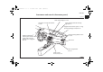
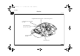
BK0132701US.book 3 ページ 2010年12月6日 月曜日 午後2時3分 Overview Instruments and controls (Floor console) N00100201273 Heated seat switch (if so equipped) P.2-10 Electric rear window defogger switch P.3-135 Gearshift or selector lever P.3-66, 3-71 Air conditioning P.5-5, 5-14 Parking brake lever P.3-54 Cup holder P.3-178 Floor console box P.3-176 Electric convertible top (ECLIPSE SPYDER) Operation indicator lamp Auxiliary Audio connector (mini-jack) P.5-63 Power outlet P.3-168 Top (OPEN) switch P.
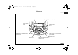
BK0132701US.book 4 ページ 2010年12月6日 月曜日 午後2時3分 Overview Interior N00100301157 ECLIPSE Except for vehicles with sunroof Window lock switch P.3-28 Vehicles with sunroof Dome light (Front)/Reading lights (if so equipped) P.3-171, 3-172, 7-50 Dome light (Front)/Reading lights P.3-170, 3-171, 7-50, 7-68 Sunroof switch P.3-28 Power door lock switch P.3-15 Power window switch P.3-26 Adjustable seat belt shoulder anchor (for front seats) P.2-19 Seat belts P.2-13 Inside rearview mirror P.
BK0132701US.book 5 ページ 2010年12月6日 月曜日 午後2時3分 Overview Interior N00100301069 ECLIPSE Supplemental restraint system - curtain air bag P.2-52 Coat hooks (if so equipped) P.3-180 Dome light (Rear) P.3-174, 7-50, 7-68 Rear shelf panel P.3-178 Rear seat P.
BK0132701US.book 6 ページ 2010年12月6日 月曜日 午後2時3分 Overview Cargo area N00100500077 ECLIPSE Tools P.6-8 Cargo area light P.3-174, 7-50, 7-69 Luggage hooks P.3-180 Luggage hooks P.3-180 Tether anchors for child restraint system P.2-28 Tether anchors for child restraint system P.2-28 Jack P.6-9 Inside rear hatch/trunk lid release P.3-18 Spare tire P.
BK0132701US.book 7 ページ 2010年12月6日 月曜日 午後2時3分 Overview Outside (Front) N00100601134 ECLIPSE Sunroof (if so equipped) Windshield wiper and washer P.3-132 P.3-28 Engine compartment P.7-6 Engine hood P.7-4 Front fog lights (if so equipped) P.3-131, 7-48, 7-57 Except for vehicles with high intensity discharge (HID) type headlights Headlight P.3-125, 7-48, 7-52 Front turn-signal, parking and side-marker lights P.3-125,3-129, 7-48, 7-56 Outside rearview mirrors P.3-58 Fuel tank filler door P.
BK0132701US.book 8 ページ 2010年12月6日 月曜日 午後2時3分 Overview Outside (Rear) N00100601251 ECLIPSE Rear window wiper and washer P.3-134 Antenna P.5-74 Satellite radio antenna (if so equipped) P.5-75 Rear hatch P.3-16 Tire inflation pressure P.7-23 Changing tires P.6-9 Tire rotation P.7-26 Tire chains P.7-29 Tire pressure monitoring system P.3-96 High-mounted stop light P.7-49 Rear hatch button P.3-16 License plate light P.7-49, 7-66 Rear-view camera (if so equipped) P.3-101 Stop and tail lights P.
BK0132701US.book 9 ページ 2010年12月6日 月曜日 午後2時3分 Overview Interior N00100301144 ECLIPSE SPYDER Window lock switch P.3-28 Power door lock switch P.3-15 Power window switch P.3-26 Dome light (Front)/Reading lights (if so equipped) P.3-171, 3-172, 7-50 Inside rearview mirror P.3-56, 3-102 Reading light (if so equipped) P.3-173, 7-50, 7-69 Sun visors P.3-166 Vanity mirror (if so equipped) P.3-167 Seat belts P.2-13 Front seats P.2-4 Head restraints P.
BK0132701US.book 10 ページ 2010年12月6日 月曜日 午後2時3分 Overview Trunk area N00100400223 ECLIPSE SPYDER Tools P.6-8 Jack P.6-9 Spare tire P.6-11 Inside emergency trunk lid release P.
BK0132701US.book 11 ページ 2010年12月6日 月曜日 午後2時3分 Overview Outside (Front) N00100601150 ECLIPSE SPYDER Windshield wiper and washer P.3-132 Engine compartment P.7-6 Engine hood P.7-4 Front fog lights P.3-131, 7-48, 7-57 Except for vehicles with high intensity discharge (HID) type headlights Headlight P.3-125, 7-48, 7-52 Front turn-signal, parking and side-marker lights P.3-125,3-129, 7-48, 7-56 Outside rearview mirrors P.3-58 Fuel tank filler door P.1-4 Locking and unlocking P.
BK0132701US.book 12 ページ 2010年12月6日 月曜日 午後2時3分 Overview Outside (Rear) N00100601248 ECLIPSE SPYDER High-mounted stop light P.7-49 Satellite radio antenna (if so equipped) P.5-75 Trunk lid button P.3-16 Antenna P.5-74 Tire inflation pressure P.7-23 Changing tires P.6-9 Tire rotation P.7-26 Tire chains P.7-29 Tire pressure monitoring system P.3-96 Trunk lid P.3-16 License plate light P.7-49, 7-66 Rear-view camera (if so equipped) P.3-101 Stop and tail lights P.3-125 Back-up lights P.
BK0132701US.
BK0132701US.book 1 ページ 2010年12月6日 月曜日 午後2時3分 Quick index If this warning light comes on or flashes while you’re driving... N00200701093 NOTE ● These warning lights will come on for a few seconds for a bulb check when the ignition key is first turned to “ON”. Warning light Do this Ref. page ● Park your vehicle in a safe place and stop the engine. Contact an authorized Mitsubishi Motors dealer or a repair facility of your choice for assistance. P.
BK0132701US.book 2 ページ 2010年12月6日 月曜日 午後2時3分 Quick index Warning light Selector lever position indicator in the instrument cluster flashes rapidly (twice per second) (if so equipped) or Engine malfunction indicator (“SERVICE ENGINE SOON” or “Check engine light”) Anti-lock braking system warning light SRS warning light 2 Do this Ref. page ● Park your vehicle in a safe place. Idle the engine until the selector lever position indicator stops flashing.
BK0132701US.book 3 ページ 2010年12月6日 月曜日 午後2時3分 Quick index Warning light Selector lever position indicator in the instrument cluster flashes slowly (once per second) (if so equipped) and or and Do this Ref. page ● Have the automatic transaxle checked at an authorized Mitsubishi Motors dealer or a repair facility of your choice as soon as possible. P.3-74 ● Park your vehicle in a safe place and turn off the engine. Restart the engine and check to see if the indicator comes on again.
BK0132701US.book 4 ページ 2010年12月6日 月曜日 午後2時3分 Quick index If you hear this sound... N00200800664 Sound Constant tone when the driver’s door is opened. 4 Do this Ref. page “Key reminder buzzer” A tone will sound if the driver’s door is opened while the ignition key is in the “LOCK” or “ACC” position. Remove the key to stop the tone. OR P.
BK0132701US.book 5 ページ 2010年12月6日 月曜日 午後2時3分 Quick index Sound Do this Ref. page Metallic squeal when you press the brake pedal while driving. “Brake pad wear alarm” The brake pads are worn down to the serviceable limit. Have the brake pads replaced at an authorized Mitsubishi Motors dealer or a repair facility of your choice. P.3-80 Tone when the ignition key is turned to the “ON” position.
BK0132701US.book 6 ページ 2010年12月6日 月曜日 午後2時3分 Quick index If the indicator flashes and a tone sounds when the electric convertible top is operated (ECLIPSE SPYDER) N00200100029 Indicator Lamp Tone 6 Ref. page ● The requirements for operation of the electric convertible top are not all satisfied. Ensure satisfaction of all the requirements. P.3-32 ● The indicator and tone indicate that the electric convertible top is not going to operate.
BK0132701US.book 7 ページ 2010年12月6日 月曜日 午後2時3分 Quick index If this problem occurs... N00200900678 Problem Cannot turn the key. Do this Ref. Page From “LOCK” to “ACC” Turn the key while jogging the steering wheel in either direction. From “ACC” to “LOCK” Vehicles with automatic transaxle: Check the position of the selector lever. The key cannot be removed unless the selector lever is set to the “P” (PARK) position. Vehicles with manual transaxle: Place the key at the “ACC” position.
BK0132701US.book 8 ページ 2010年12月6日 月曜日 午後2時3分 Quick index Problem Do this Ref. page The engine coolant temperature gauge indicator is at the “H” (hot) position. Steam comes out of the engine compartment. The vehicle is stuck in sand, mud, or snow. ! The engine is overheated. Carefully stop the vehicle in a safe place. P.
BK0132701US.book 9 ページ 2010年12月6日 月曜日 午後2時3分 Quick index Problem Do this The brakes are not functioning properly after driving through Dry out the brakes by driving slowly while lightly pressing the brake pedal. water. The automatic transaxle does not shift when accelerating and/or the vehicle does not easily begin to move. There may be a problem in the automatic transaxle. Have the vehicle inspected by an authorized Mitsubishi Motors dealer or a repair facility of your choice.
BK0132701US.
BK0132701US.book 1 ページ 2010年12月6日 月曜日 午後2時3分 General information Fuel selection . . . . . . . . . . . . . . . . . . . . . . . . . . . . .1Filling the fuel tank . . . . . . . . . . . . . . . . . . . . . . . .1Modifications to and racing of your vehicle . . . . .1Mitsubishi Motors genuine parts . . . . . . . . . . . . . .1California Perchlorate Materials Requirements. . .
BK0132701US.book 2 ページ 2010年12月6日 月曜日 午後2時3分 General information Fuel selection Octane requirement N00301000808 Your vehicle is designed to use unleaded gasoline only. It is equipped with a fuel filler tube especially designed to accept only a small diameter unleaded gasoline dispensing nozzle. 1 ! WARNING ● Gasoline is highly flammable and explosive. You could be burned, seriously injured or killed when handling it.
BK0132701US.book 3 ページ 2010年12月6日 月曜日 午後2時3分 General information Ethanol (Gasohol) Sulfur in gasoline A mixture of up to 10 % ethanol (grain alcohol) and 90 % unleaded gasoline may be used in your vehicle, provided the octane number is at least as high as that recommended for unleaded gasoline. Your vehicle may have been designed to satisfy California’s low-emission regulations based on clean-burning low-sulfur gasoline.
BK0132701US.book 4 ページ 2010年12月6日 月曜日 午後2時3分 General information 1 ● Repeatedly driving short distances at low speeds can cause deposits to form in the fuel system and engine, resulting in poor starting and poor acceleration. If these problems occur, you are advised to add a detergent additive to the gasoline when you refuel the vehicle. The additive will remove the deposits, thereby returning the engine to a normal condition. Be sure to use a genuine Mitsubishi detergent additive.
BK0132701US.book 5 ページ 2010年12月6日 月曜日 午後2時3分 General information Fuel tank capacity 17.7 gal (67 L) 3. Open the fuel tank filler pipe by slowly turning the cap counterclockwise. Refueling 1. Before filling with fuel, stop the engine. 2. The fuel tank filler is located on the rear driver side of your vehicle. To open the fuel tank filler door, hook a finger behind the door, and pull the door toward you.
BK0132701US.book 6 ページ 2010年12月6日 月曜日 午後2時3分 General information 4. To fill with fuel correctly depends mainly on correct handling of the fuel filler nozzle. Do not tilt the nozzle. Insert the nozzle in the tank port as far as it will go. ! 1 CAUTION ● Your vehicle can only be operated using unleaded gasoline. Serious engine and catalytic converter damage will result if leaded gasoline is used. 5. When the nozzle stops automatically, do not try to add more fuel.
BK0132701US.book 7 ページ 2010年12月6日 月曜日 午後2時3分 General information Modifications to and racing of your vehicle Installation of accessories N00301700023 N00301600136 This vehicle should not be modified with non-Mitsubishi Motors genuine parts. Mitsubishi Motors designs and manufactures high quality vehicles with an emphasis on safety and durability.
BK0132701US.book 8 ページ 2010年12月6日 月曜日 午後2時3分 General information ! 1 WARNING ● If you choose to use a cellular phone while driving, you must not allow that usage to distract you in the safe operation of your vehicle. Anything, including cellular phone usage, that distracts you from the safe operation of your vehicle increases your risk of an accident. Refer to and follow all state and local laws in your area regarding cellular phone usage while driving.
BK0132701US.book 9 ページ 2010年12月6日 月曜日 午後2時3分 General information Mitsubishi Motors genuine parts N00301400105 Mitsubishi Motors Genuine Parts are designed and manufactured to meet high standards of performance, and are recommended for all of your maintenance needs. Also available from your Mitsubishi Motors dealer are a wide variety of accessories to personalize your new vehicle.
BK0132701US.
BK0132701US.book 1 ページ 2010年12月6日 月曜日 午後2時3分 Seat and restraint systems Seats . . . . . . . . . . . . . . . . . . . . . . . . . . . . . . . . . . . .2Seats and restraint systems. . . . . . . . . . . . . . . . . . .2Front seats . . . . . . . . . . . . . . . . . . . . . . . . . . . . . . .2Rear seat. . . . . . . . . . . . . . . . . . . . . . . . . . . . . . . . .2Head restraints . . . . . . . . . . . . . . . . . . . . . . . . . . . .2Seat belts . . . . . . . . . . . . . . . . . . . . . . . . . . . . . . . .
BK0132701US.book 2 ページ 2010年12月6日 月曜日 午後2時3分 Seat and restraint systems Seats N00408400323 2 1 - Front seats To adjust the seat forward or backward → P.2-5 To adjust the seatback → P.2-6 To adjust the seat height (Driver’s side only) → P.2-7 To adjust the lumbar support (Driver’s side only) → P.2-9 For access to the rear seat (Passenger’s side only) → P.2-10 ● Heated seats (if so equipped) → P.2-10 ● ● ● ● ● 2-2 2 - Rear seat ● Folding the seatbacks forward (ECLIPSE only) → P.
BK0132701US.book 3 ページ 2010年12月6日 月曜日 午後2時3分 Seat and restraint systems Seats and restraint systems N00401600195 Your vehicle has seat belts and other features that help protect you and your passengers in an accident. Seat belts are the most important safety device. When worn properly, seat belts can reduce the chance of serious injury or death in various types of crashes.
BK0132701US.book 4 ページ 2010年12月6日 月曜日 午後2時3分 Seat and restraint systems Front seats N00401800201 Position the driver’ s seat as far back as possible while maintaining a position that still enables you to fully apply the pedals, easily control the steering wheel and safely operate the vehicle. Manual seat 2 2-4 Power seat ! WARNING ● Do not attempt to adjust the seat while driving. This can cause loss of vehicle control and result in an accident.
BK0132701US.book 5 ページ 2010年12月6日 月曜日 午後2時3分 Seat and restraint systems ! CAUTION ● Make sure that the seat is adjusted by an adult. If it is adjusted by a child, an unexpected accident might occur. ● Do not place a cushion or the like between your back and the seatback while driving. The effectiveness of the head restraints will be reduced in the event of an accident. ● When sliding the seats, be careful not to catch your hand or leg.
BK0132701US.book 6 ページ 2010年12月6日 月曜日 午後2時3分 Seat and restraint systems Power seat Push the switch to adjust the seat forward or backward to the desired position. Release the switch, and the seat will lock at that position. To adjust the seatback N00402000167 To adjust the seatback, lean forward slightly, gently pull the seatback lock lever up, then lean backward to a comfortable position and release the lever. The seatback will lock in place.
BK0132701US.book 7 ページ 2010年12月6日 月曜日 午後2時3分 Seat and restraint systems ! WARNING ● To reduce the risk of serious injury or death in the event of an accident or sudden stop, all seatbacks should be kept in the upright position while the vehicle is in motion. To adjust the seat height (Driver’s side only) N00402100100 Manual seat Turn the dial to raise or lower the whole seat cushion. Seat belt performance during an accident can be adversely affected if the seatbacks are reclined.
BK0132701US.book 8 ページ 2010年12月6日 月曜日 午後2時3分 Seat and restraint systems Power seat Front and/or rear parts of the seat cushion height can be adjusted. Rear part of the seat cushion Operate the switch to raise or lower the rear part of the seat cushion. NOTE ● To prevent the battery from running down, operate the power seat with the engine running. 2 Front part of the seat cushion Operate the switch to raise or lower the front part of the seat cushion.
BK0132701US.book 9 ページ 2010年12月6日 月曜日 午後2時3分 Seat and restraint systems Whole seat cushion Operate the center of the switch to raise or lower the whole seat cushion. To adjust the lumbar support (Driver’s side only) N00402200097 A lumbar support is included in the seatback of the driver’s seat.
BK0132701US.book 10 ページ 2010年12月6日 月曜日 午後2時3分 Seat and restraint systems For access to the rear seat (Passenger’s side only) Heated seats (if so equipped) N00402400028 N00435600293 The heated seats can be operated when the ignition key is in the “ON” position. 2 For rear seat passenger entry or exit, the front passenger seat and seatback can be moved forward by either pulling up the seat lock lever or depressing the lock release pedal behind the seat.
BK0132701US.book 11 ページ 2010年12月6日 月曜日 午後2時3分 Seat and restraint systems ! Rear seat CAUTION ● Switch off the seat heaters when not in use. Operate the heaters at high for quick heating. After the seat has become warm, set the heater to low to keep it warm. Slight variations in the seat temperature may be felt while using the heated seats. This is caused by the operation of the heater’s internal thermostat and does not indicate a malfunction.
BK0132701US.book 12 ページ 2010年12月6日 月曜日 午後2時3分 Seat and restraint systems ! 2 WARNING ● Do not allow anyone to ride in the cargo area while the vehicle is in motion. People who are not properly seated and restrained can be seriously injured or killed in an accident. ● To avoid reducing rearward vision, do not load cargo or luggage higher than the top of the seatback. ● Firmly secure cargo and luggage. Unsecured cargo and luggage can move during braking or in an accident, causing serious injury or death.
BK0132701US.book 13 ページ 2010年12月6日 月曜日 午後2時3分 Seat and restraint systems ! Seat belts WARNING ● In order to minimize the risk of a neck injury due to a rear impact, the driver and front passenger seatbacks must be adjusted to the upright position before vehicle operation. The driver should never adjust the seat while the vehicle is in motion. ● Never place a cushion or similar device on the seatback.
BK0132701US.book 14 ページ 2010年12月6日 月曜日 午後2時3分 Seat and restraint systems ! 2 WARNING ● To reduce the risk to a front seat passenger of serious injury or death from a deploying air bag, make sure the passenger always wears the seat belt properly, remains seated all the way back and upright in their seat, and moves the seat as far back as possible. Refer to “Supplemental Restraint System (SRS) air bag” on page 2-36 for additional information.
BK0132701US.book 15 ページ 2010年12月6日 月曜日 午後2時3分 Seat and restraint systems 1. Occupants should always sit back in their seats with their backs against the upright seatback. To reduce the risk of serious injury or death during deployment of the air bag, adjust the driver’s seat as far back as possible while maintaining a position that still enables you to fully apply the pedals, easily control the steering wheel, and safely operate the vehicle.
BK0132701US.book 16 ページ 2010年12月6日 月曜日 午後2時3分 Seat and restraint systems 2. Grasp the latch plate and slide it up the webbing so that it easily pulls across your body. 3. Pull the seat belt out slowly while holding the latch plate. Push the latch plate into the buckle until you hear a “click”. Pull up on the belt to be sure the latch plate is locked securely in the buckle. 2 NOTE ● If the seat belt locks up and cannot be pulled out, pull it once with force and let it retract all the way.
BK0132701US.book 17 ページ 2010年12月6日 月曜日 午後2時3分 Seat and restraint systems 4. The lap part of the belt must always be worn low and snug across the hips. Pull up on the shoulder portion of the belt to take up any slack in the lap belt. NOTE ● With the exception of the seat belt for the driver, the seat belts in all other seating positions are equipped with an Automatic Locking Retractor (ALR) function.
BK0132701US.book 18 ページ 2010年12月6日 月曜日 午後2時3分 Seat and restraint systems Driver’s seat belt reminder/warning light N00418400137 A tone and warning light are used to remind the driver to fasten the seat belt. 2 When the ignition key is turned to the “ON” position, the warning light will come on and a tone will sound for about 6 seconds.
BK0132701US.book 19 ページ 2010年12月6日 月曜日 午後2時3分 Seat and restraint systems Front passenger seat belt warning light N00418300093 The front passenger seat belt warning light is located above the central vents in the instrument panel. Adjustable seat belt shoulder anchor (ECLIPSE only, front seats) N00406300230 To move the anchor down, press the lock knob (A) and slide the anchor down to the desired position. To move the anchor up, slide the anchor up to the desired position.
BK0132701US.book 20 ページ 2010年12月6日 月曜日 午後2時3分 Seat and restraint systems ! 2 WARNING ● Always adjust the shoulder belt anchor so that the shoulder belt is positioned across the center of your shoulder without touching your neck. The shoulder belt should not be able to fall off your shoulder. Failure to follow this instruction can adversely affect seat belt performance and increase the risk of serious injury or death in the event of an accident.
BK0132701US.book 21 ページ 2010年12月6日 月曜日 午後2時3分 Seat and restraint systems ! WARNING ● Make sure the part of the seat belt webbing you inserted into the seat belt guide is not twisted. Twisted webbing may adversely affect seat belt performance. Seat belt extender N00406700087 When your seat belt, even fully extended, is not long enough, a seat belt extender must be obtained. The extender may be used for either of the front seats.
BK0132701US.book 22 ページ 2010年12月6日 月曜日 午後2時3分 Seat and restraint systems Seat belt use during pregnancy N00406800075 Seat belts work for everyone, including pregnant women. Like all occupants, pregnant women are more likely to be seriously injured or killed in an accident if they do not wear seat belts. ! 2 WARNING ● To reduce the risk of serious injury or death to pregnant women and unborn children in an accident, pregnant women should always wear a seat belt.
BK0132701US.book 23 ページ 2010年12月6日 月曜日 午後2時3分 Seat and restraint systems The seat belt pre-tensioner system includes the following components: When the seat belt pre-tensioners activate, some smoke is released and a loud noise will be heard. The smoke is not harmful, but care should be taken not to intentionally inhale it, as it may cause some temporary irritation to people with respiratory problems.
BK0132701US.book 24 ページ 2010年12月6日 月曜日 午後2時3分 Seat and restraint systems Child restraints SRS warning light N00408700049 This warning light tells you if there is a problem involving the SRS air bags and the pre-tensioner seat belts. Refer to “SRS warning light” on page 2-44. Force limiter system N00408900070 2 In the event of an accident, the seat belt force limiter system will help reduce the force applied to the driver and front seat passenger.
BK0132701US.book 25 ページ 2010年12月6日 月曜日 午後2時3分 Seat and restraint systems ● Children who weigh more than 40 pounds (18 kg) or who are more than 40 inches (100 cm) tall, regardless of age, should use a suitable child seat or a booster seat (including a booster cushion) in the rear seat until the vehicle’s lap/shoulder belt fits them properly. ! WARNING ● All children must be seated in the rear seat, and properly restrained.
BK0132701US.book 26 ページ 2010年12月6日 月曜日 午後2時3分 Seat and restraint systems ! WARNING ● Your vehicle is also equipped with a front passenger air bag. Never put REAR-FACING CHILD RESTRAINTS or INFANT RESTRAINTS in the front passenger seat. This places the infant too close to the passenger air bag. During deployment of the air bag, the infant can be seriously injured or killed. Rear-facing child restraints or infant restraints must only be used in the rear seat.
BK0132701US.book 27 ページ 2010年12月6日 月曜日 午後2時3分 Seat and restraint systems ! WARNING ● It is important to use an approved rear-facing infant restraint until the infant is one year old (unless the infant outgrows the seat sooner). This allows the infant’s neck and spine to develop enough to support the weight of their head in the event of an accident. ● When installing a child restraint system, follow the instructions provided by the manufacturer and follow the directions in this manual.
BK0132701US.book 28 ページ 2010年12月6日 月曜日 午後2時3分 Seat and restraint systems Installing a child restraint system using the LATCH (Lower Anchors and Tethers for children) system N00418800043 Lower anchor locations Tether anchor locations (ECLIPSE only) N00418900086 Your vehicle has 2 attachment points on the floor of the cargo area. These are for securing a child restraint system tether strap to each of the 2 rear seating positions in your vehicle.
BK0132701US.book 29 ページ 2010年12月6日 月曜日 午後2時3分 Seat and restraint systems Examples of child restraint systems compatible with the LATCH system N00419000101 ABCD- Using the LATCH system N00419100203 1. Push the anchor connectors (A) on the child restraint system into the slits (B) in accordance with the instructions provided by the child restraint system manufacturer.
BK0132701US.book 30 ページ 2010年12月6日 月曜日 午後2時3分 Seat and restraint systems NOTE ● In order to secure a child restraint systems compatible with the LATCH system, use the lower anchor points in the rear seat. It is not necessary to use the vehicle’s seat belt. ! 2 WARNING In an ECLIPSE, install a tether strap in accordance with steps 2 to 4 shown hereafter. 2. Open the rear hatch. Remove the rear shelf panel. Refer to “Rear shelf panel” on page 3-178. 3.
BK0132701US.book 31 ページ 2010年12月6日 月曜日 午後2時3分 Seat and restraint systems 4. Latch the tether strap hook (G) of the child restraint system to the tether anchor (H) and tighten the tether strap so it is securely fastened.
BK0132701US.book 32 ページ 2010年12月6日 月曜日 午後2時3分 Seat and restraint systems Installation: 1. Place the child restraint system in a rear seating position. 2. Route the seat belt through the child restraint system according to the instructions provided by the child restraint manufacturer. Then insert the seat belt latch plate into the buckle. Make sure you hear a “click” when you insert the latch plate into the buckle. 3.
BK0132701US.book 33 ページ 2010年12月6日 月曜日 午後2時3分 Seat and restraint systems 5. After confirming that the belt is locked, grab the shoulder part of the belt near the buckle and pull up to remove any slack from the lap part of the belt allowing the slack to feed into the retractor. Remember, if the lap belt portion is not tight, the child restraint system will not be secure.
BK0132701US.book 34 ページ 2010年12月6日 月曜日 午後2時3分 Seat and restraint systems 8. Latch the tether strap hook (B) of the child restraint system to the tether anchor (C) and tighten the tether strap so it is securely fastened. 2 NOTE ● When using a child restraint system that requires a tether strap, the rear shelf panel cannot be installed. ! WARNING ● Child restraint tether anchors are designed only to withstand loads from correctly fitted child restraint systems.
BK0132701US.book 35 ページ 2010年12月6日 月曜日 午後2時3分 Seat and restraint systems Children who have outgrown child restraint systems N00407600490 Children who have outgrown a child restraint system should be seated in the rear seat and wear the seat belt.
BK0132701US.book 36 ページ 2010年12月6日 月曜日 午後2時3分 Seat and restraint systems Supplemental Restraint System (SRS) - air bag N00407700606 This vehicle is equipped with a Supplemental Restraint System (SRS), which includes air bags for the driver and front passenger.
BK0132701US.book 37 ページ 2010年12月6日 月曜日 午後2時3分 Seat and restraint systems ! WARNING ● IT IS VERY IMPORTANT TO BE PROPERLY SEATED. • A driver or front passenger sitting too close to the steering wheel or instrument panel during air bag deployment can be seriously injured or killed. • Air bags inflate very quickly and with great force.
BK0132701US.book 38 ページ 2010年12月6日 月曜日 午後2時3分 Seat and restraint systems ! WARNING ● Infants and small children should never ride unrestrained, or lean against the instrument panel. They should never ride held in your arms or on your lap. They can be seriously injured or killed in an accident, especially when the air bags inflate. Infants and children should be properly seated in the rear seat in an appropriate child restraint system. Refer to “Child restraints” on page 2-24.
BK0132701US.book 39 ページ 2010年12月6日 月曜日 午後2時3分 Seat and restraint systems ! WARNING ● FRONT-FACING CHILD RESTRAINTS should be used in the rear seat whenever possible. If they must be used in the front passenger seat, move the seat to the most rearward position and make sure the child stays in the child restraint, properly restrained. Failure to follow these instructions could result in serious injury or death to the child.
BK0132701US.book 40 ページ 2010年12月6日 月曜日 午後2時3分 Seat and restraint systems When the impact sensors detect a sufficient front or side impact to deploy the air bag(s), the appropriate air bag(s) will be deployed. When air bags deploy, some smoke is released accompanied by a loud noise. The smoke is not harmful, but do not intentionally inhale the smoke as it may cause temporary irritation to people with respiratory problems.
BK0132701US.book 41 ページ 2010年12月6日 月曜日 午後2時3分 Seat and restraint systems Event Data Recording Driver’s seat position sensor N00418600054 N00417900092 Your vehicle is equipped with an “EDR” - Event Data Recorder which is capable of collecting and storing data in the event of an air bag deployment. The driver’s seat position sensor is attached to the seat rail and provides the air bag control unit with information on the seat’s fore-aft position.
BK0132701US.book 42 ページ 2010年12月6日 月曜日 午後2時3分 Seat and restraint systems Passenger’s seat weight sensors N00418000319 2 The passenger’s seat weight sensors are attached to the seat rails and provide the air bag control unit with information regarding the weight on the front passenger seat. The air bag control unit controls deployment of the passenger’s front air bag in accordance with the information it receives from this sensor.
BK0132701US.book 43 ページ 2010年12月6日 月曜日 午後2時3分 Seat and restraint systems ! WARNING ● If the vehicle is involved in a severe impact, have the sensors inspected by an authorized Mitsubishi Motors dealer as soon as possible. Passenger’s air bag off indicator N00418100219 The passenger air bag off indicator is located in the instrument panel. 2 The indicator normally comes on when the ignition switch is turned to the “ON” position and goes out a few seconds later.
BK0132701US.book 44 ページ 2010年12月6日 月曜日 午後2時3分 Seat and restraint systems 2 [For ECLIPSE SPYDER] In the following situations, the indicator will stay on to show that the passenger’s front air bag and the passenger’s side air bag are not operational. ● The passenger’s seat weight sensors sense a weight of less than about 66 pounds (30 kg) on the front passenger seat. ● The front passenger’s seat is not occupied.
BK0132701US.book 45 ページ 2010年12月6日 月曜日 午後2時3分 Seat and restraint systems ! WARNING ● If any of the following conditions occur, the SRS and/or seat belt pre-tensioners are not working properly and you should immediately have it inspected by an authorized Mitsubishi Motors dealer: • The SRS warning light does not come on when the ignition key is turned to the “ON” or “START” position. • The SRS warning light does not go out after several seconds. • The SRS warning light comes on while driving.
BK0132701US.book 46 ページ 2010年12月6日 月曜日 午後2時3分 Seat and restraint systems Deployment of front air bags N00408000459 The front air bags ARE DESIGNED TO DEPLOY when… Head-on collision with a solid wall at speeds of approx. 15 mph (25 km/h) or higher Moderate to severe frontal impact within the shaded area between the arrows 2 The front air bags are designed to deploy when the vehicle suffers a moderate to severe frontal impact. A typical condition is shown in the illustration to the left.
BK0132701US.book 47 ページ 2010年12月6日 月曜日 午後2時3分 Seat and restraint systems The front air bags MAY NOT DEPLOY when … In certain types of front collisions, the front air bags may not deploy, even if the deformation of the body seems to be large, because the vehicle’s body structure is designed to absorb the impact and deform in order to help protect the occupants. Some typical situations where the front air bags may not deploy are shown in the illustrations.
BK0132701US.book 48 ページ 2010年12月6日 月曜日 午後2時3分 Seat and restraint systems The front air bags ARE NOT DESIGNED TO DEPLOY when … Rear end collision to your vehicle The front air bags are not designed to deploy in situations where they cannot provide protection to the occupants. Some typical situations are shown in the illustrations. Because the front air bags do not protect the occupants in all types of collisions, be sure to always wear your seat belts properly.
BK0132701US.book 49 ページ 2010年12月6日 月曜日 午後2時3分 Seat and restraint systems The front air bags MAY DEPLOY when … The front air bags may deploy if the underside of the vehicle suffers a moderate to severe impact (undercarriage impact). Some typical situations are shown in the illustrations.
BK0132701US.book 50 ページ 2010年12月6日 月曜日 午後2時3分 Seat and restraint systems ! WARNING ● Do not attach anything to the steering wheel’s padded cover, such as trim material, badges, etc. These could strike and injure an occupant if the air bag inflates. ● Do not set anything on, or attach anything to, the instrument panel above the glove compartment. Such items could strike and injure an occupant if the air bag inflates.
BK0132701US.book 51 ページ 2010年12月6日 月曜日 午後2時3分 Seat and restraint systems Side air bag system N00408100290 The side air bags (A) are contained in the driver and front passenger seatbacks. [For ECLIPSE] The side air bag is designed to inflate only on the side of the vehicle that is impacted, even with no passenger in the front seat. [For ECLIPSE SPYDER] The side air bag is designed to inflate only on the side of the vehicle that is impacted.
BK0132701US.book 52 ページ 2010年12月6日 月曜日 午後2時3分 Seat and restraint systems A label is attached to the seatbacks in vehicles with side air bags. 2 2-52 Curtain air bag system (ECLIPSE only) N00419200028 The curtain air bags are contained in the front and rear pillars and roof side rail. The curtain air bag is designed to inflate only on the side of the vehicle that is impacted, even with no passenger in the front seat.
BK0132701US.book 53 ページ 2010年12月6日 月曜日 午後2時3分 Seat and restraint systems ! WARNING ● The side air bag and curtain air bag can cause serious injury or death to anyone too close to the air bag when it deploys. To reduce the risk of injury from a deploying side air bag and curtain air bags, driver and front passenger must be properly restrained and seated well back, upright, and in the middle of the seat. Do not lean against the door.
BK0132701US.book 54 ページ 2010年12月6日 月曜日 午後2時3分 Seat and restraint systems ! WARNING ● Do not attach a microphone (A) or any other object around the part where the curtain air bag (B) deploys, such as on the windshield, side door glass or front and rear pillars and roof side rail. When the curtain air bag inflate, the microphone or other object may be hurled with great force or the curtain air bag may not inflate correctly, resulting in death or serious injury.
BK0132701US.book 55 ページ 2010年12月6日 月曜日 午後2時3分 Seat and restraint systems Deployment of side air bag and curtain air bag N00408200392 The side air bag and curtain air bag ARE DESIGNED TO DEPLOY when … A side air bag and curtain air bag are designed to deploy when the vehicle suffers a moderate to severe side impact to the middle of the passenger compartment. The typical situation is shown in the illustration.
BK0132701US.
BK0132701US.book 57 ページ 2010年12月6日 月曜日 午後2時3分 Seat and restraint systems The side air bag and curtain air bag ARE NOT DESIGNED TO DEPLOY when … The side air bag and curtain air bag are not designed to deploy in situations where they cannot provide protection to the occupants. Some typical situations are shown in the illustrations. Because the side air bags and curtain air bags do not protect the occupants in all types of collisions, be sure to always wear your seat belts properly.
BK0132701US.book 58 ページ 2010年12月6日 月曜日 午後2時3分 Seat and restraint systems ! WARNING ● For ECLIPSE, if you find a crack in or damage to the front pillar, rear pillar, or roof side rail where the curtain air bag is located, have the SRS inspected by an authorized Mitsubishi Motors dealer. NOTE 2 ● When you transfer ownership of the vehicle to another person, we urge you to alert the new owner that it is equipped with the SRS and refer that owner to the applicable sections in this owner’s manual.
BK0132701US.book 59 ページ 2010年12月6日 月曜日 午後2時3分 Seat and restraint systems Warning labels N00408600282 Occupant restraint warning labels for the SRS are located in the vehicle as shown in the illustration. 2 * - Located in the passenger’s side as well.
BK0132701US.
BK0132701US.book 1 ページ 2010年12月6日 月曜日 午後2時3分 Features and controls Break-in recommendations . . . . . . . . . . . . . . . . . .3Keys . . . . . . . . . . . . . . . . . . . . . . . . . . . . . . . . . . . .3Electronic immobilizer (Anti-theft starting system). . . . . . . . . . . . . . . . .3Keyless entry system . . . . . . . . . . . . . . . . . . . . . . .3Door locks . . . . . . . . . . . . . . . . . . . . . . . . . . . . . . .3Power door locks . . . . . . . . . . . . . . . . . . . . . . . . . .
BK0132701US.book 2 ページ 2010年12月6日 月曜日 午後2時3分 Features and controls Keys Break-in recommendations N00508700226 3 Advanced automobile manufacturing techniques permit you to operate your new vehicle without requiring a long break-in period of low-speed driving. However, you can add to the future performance and economy of your vehicle by observing the following precautions during the first 300 miles (500 km). Drive your vehicle at moderate speeds during the break-in period. ● Avoid revving the engine.
BK0132701US.book 3 ページ 2010年12月6日 月曜日 午後2時3分 Features and controls NOTE ● The key number (A) is stamped on the key number plate as shown in the illustration. Make a record of the key number and store the key and key number plate in separate places, so that you can order a key from your authorized Mitsubishi Motors dealer if the original keys are lost. ● The key is a precision electronic device with a built-in signal transmitter. Please observe the following in order to prevent damage.
BK0132701US.book 4 ページ 2010年12月6日 月曜日 午後2時3分 Features and controls NOTE 3 ● In the following cases, the vehicle may not be able to recognize the registered ID code from the key. This means the engine will not start even when the registered key is turned to the “START” position.
BK0132701US.book 5 ページ 2010年12月6日 月曜日 午後2時3分 Features and controls NOTE ● Electronic immobilizer is not compatible with commercially available remote starting systems. Use of commercially available remote starting systems may result in vehicle starting problems and a loss of security protection. ● A system failure is suspected when the ignition key is turned to the “START” position, and the engine does not start. In such a case, contact an authorized Mitsubishi Motors dealer.
BK0132701US.book 6 ページ 2010年12月6日 月曜日 午後2時3分 Features and controls 4. When the immobilizer indicator starts blinking, turn the second valid key to the “LOCK” position and remove it. Within 30 seconds after doing so, insert a blank immobilizer key into the ignition and turn it to the “ON” position. Perform this operation no more than 30 seconds after the immobilizer indicator starts blinking. When registration of the ID code is complete, the immobilizer indicator will come on for 3 seconds then go off.
BK0132701US.book 7 ページ 2010年12月6日 月曜日 午後2時3分 Features and controls Keyless entry system General information Your electronic immobilizer operates on a radio frequency subject to Federal Communications Commission (FCC) Rules (For vehicles sold in U.S.A.) and Industry Canada Rules (For vehicles sold in Canada). This device complies with Part 15 of the FCC Rules and RSS-210 of the Industry Canada Rules. Operation is subject to the following two conditions. ● This device may not cause harmful interference.
BK0132701US.book 8 ページ 2010年12月6日 月曜日 午後2時3分 Features and controls To lock Press the LOCK button (1) to lock all the doors and the rear hatch or trunk lid. If the dome light switch is in the door position, the dome light will blink once. The turn signal lights will also blink once. NOTE ● If you press the LOCK button (1) after locking the doors and the rear hatch or trunk lid, the horn will sound once to confirm that they are locked.
BK0132701US.book 9 ページ 2010年12月6日 月曜日 午後2時3分 Features and controls Horn deactivation/reactivation The answerback function can be set in the following three ways. Each time the answerback function is set, a tone will sound to tell you the condition of the answerback function. One chime: The horn will sound if the doors and the rear hatch or trunk lid are locked with the keyless entry system.
BK0132701US.book 10 ページ 2010年12月6日 月曜日 午後2時3分 Features and controls NOTE 3 ● The indicator light (5) comes on each time a switch is pressed. ● The keyless entry system does not work if the key is in the ignition. ● The remote control transmitter can be used from about 40 feet (12 m) away. However, this distance may change if your vehicle is near a TV transmitting tower, a power station, or a radio station.
BK0132701US.book 11 ページ 2010年12月6日 月曜日 午後2時3分 Features and controls Procedure for replacing the remote control transmitter battery 1. With the Mitsubishi mark facing you, insert the cloth-covered tip of a flat blade screwdriver into the notch in the remote control transmitter case and use it to open the case. 2. Remove the remote control transmitter from the remote control transmitter case. Then, open the remote control transmitter using the method described in step 1. 3 3. Remove the old battery.
BK0132701US.book 12 ページ 2010年12月6日 月曜日 午後2時3分 Features and controls 4. Install a new battery with the + side (A) down. + side - side 3 Coin type battery CR1620 5. Close the remote control transmitter firmly. 6. Place the remote control transmitter in the remote control transmitter case, then securely close the remote control transmitter case. 7. Check the keyless entry system to see that it works. NOTE ● You may purchase a replacement battery at an electric appliance store.
BK0132701US.book 13 ページ 2010年12月6日 月曜日 午後2時3分 Features and controls Door locks N00509200202 ! WARNING ● Make sure all doors are tightly closed and locked while driving. • Locked doors, in combination with the use of seat belts, can help reduce the risk of ejection in an accident. • Locked doors can help keep passengers, especially small children, from opening doors and falling out of moving vehicles.
BK0132701US.book 14 ページ 2010年12月6日 月曜日 午後2時3分 Features and controls To lock or unlock the door from the inside Move the lock knob to the lock position to lock the door. All doors should be kept locked while driving. To lock the door without using the key 1. Move the inside lock knob to the locked position. 2. Be sure the keys are not inside the vehicle. Close the door. 3 1- Lock 2- Unlock The driver’s door can be unlocked without using the lock knob by pulling on the inside door handle.
BK0132701US.book 15 ページ 2010年12月6日 月曜日 午後2時3分 Features and controls Power door locks Short stroke mechanism N00553500022 The short stroke mechanism makes the doors easier to open and close by raising and lowering the door window glass as the doors are opened and closed. When you pull a door handle to open a door whose window is closed, the window will open slightly. While the door is open, the window will remain in the slightly open position.
BK0132701US.book 16 ページ 2010年12月6日 月曜日 午後2時3分 Features and controls Rear hatch (ECLIPSE)/Trunk lid (ECLIPSE SPYDER) N00510000037 ! WARNING ● It is dangerous to drive with the rear hatch or trunk lid open since carbon monoxide (CO) gas can enter the cabin. CO is an invisible, odorless gas that can cause unconsciousness and even death. 3 ! CAUTION ● Do not stand behind the exhaust pipe when loading and unloading luggage. Heat from the exhaust could lead to burns.
BK0132701US.book 17 ページ 2010年12月6日 月曜日 午後2時3分 Features and controls 2. Slip your hand into the gap (B) under the rear hatch or trunk, and raise the rear hatch or trunk lid to open it. ECLIPSE ECLIPSE SPYDER To close N00554200039 Pull the rear hatch grip (A) or trunk lid downward as illustrated and let it go before the rear hatch or trunk lid closes completely. Gently slam the rear hatch or trunk lid from the outside so that it is completely closed.
BK0132701US.book 18 ページ 2010年12月6日 月曜日 午後2時3分 Features and controls Inside rear hatch/trunk lid release 1. Open the lid (A) inside of the cargo area. N00509800149 ECLIPSE The inside rear hatch release provides a way to open the rear hatch in the case of a discharged battery. The rear hatch release lever (see illustration) is mounted in the cargo area. 3 2. Move the lever (B) up to unlock the rear hatch.
BK0132701US.book 19 ページ 2010年12月6日 月曜日 午後2時3分 Features and controls 3. Push out on the rear hatch to open it. ! The trunk lid key cylinder (see illustration) is located near the sub woofer. CAUTION ● Always keep the release lever lid on rear hatch closed when driving so that your cargo cannot accidentally bump the lever and open the rear hatch. ECLIPSE SPYDER The inside trunk lid key cylinder provides a way to open the trunk lid in the case of a discharged battery. 1.
BK0132701US.book 20 ページ 2010年12月6日 月曜日 午後2時3分 Features and controls 3. Insert the key and turn it clockwise. Inside emergency trunk lid release (ECLIPSE SPYDER) N00509800110 The emergency trunk lid release provides a way to open the trunk lid from inside the trunk. It was developed to help prevent death and serious injuries, to children who might become locked inside a vehicle trunk.
BK0132701US.book 21 ページ 2010年12月6日 月曜日 午後2時3分 Features and controls You and your family should familiarize yourselves with the location and operation of the emergency trunk lid release handle. Children should be taught not to play in or around vehicles. ! To open the trunk from the inside, pull the handle in the direction of the arrow on the handle. Push up on the trunk lid to open the trunk and climb out. WARNING Handle ● Children should never be left unsupervised in or around vehicles.
BK0132701US.book 22 ページ 2010年12月6日 月曜日 午後2時3分 Features and controls Theft-alarm system Armed stage N00510200068 The theft-alarm system is designed to provide protection from unauthorized entry into the vehicle. This system is operated in three stages: the first is the “armed” stage, the second is the “alarm” stage, and third is the “disarmed” stage. If triggered, the system provides both audible and visual alarm signals. N00510300069 Park the vehicle and stop the engine.
BK0132701US.book 23 ページ 2010年12月6日 月曜日 午後2時3分 Features and controls After completion of the steps above, the theft-alarm indicator (A) will illuminate for approximately 20 seconds and keeps blinking on and off, indicating that the system is armed. NOTE ● The system will be armed even if the engine hood is open, but when the system is set, be sure that the engine hood is locked.
BK0132701US.book 24 ページ 2010年12月6日 月曜日 午後2時3分 Features and controls Alarm stage 2. The horn will sound intermittently for 3 minutes. N00510400060 The alarm will be activated if any of the following occur while the vehicle is parked and the system is armed. 1. One of the doors and the rear hatch or trunk lid is opened without the remote control transmitter. 2. The engine hood is opened from the outside. Horn sounds! Headlights blink on and off! Type of alarm When the alarm is activated: 1.
BK0132701US.book 25 ページ 2010年12月6日 月曜日 午後2時3分 Features and controls Disarmed stage Testing the theft-alarm system N00510500061 N00510600059 The system will be disarmed when either of the following steps are taken: 1. All doors and the rear hatch or trunk lid are unlocked by the remote control transmitter. 2. The ignition key is turned to the “ACC” or “ON” position. 3.
BK0132701US.book 26 ページ 2010年12月6日 月曜日 午後2時3分 Features and controls Power windows NOTE N00510800338 ● Depending on the position of the door window, the door window may briefly stop then continue moving before reaching the fully closed position. ● Never try to operate the main switch and sub switch in different directions at the same time. This will freeze the window in position. ● Operating the power windows repeatedly with the engine stopped will run down the battery.
BK0132701US.book 27 ページ 2010年12月6日 月曜日 午後2時3分 Features and controls Main switch Sub switch The main switch located on the driver’s door can be used to operate all the windows. The windows will move while the switch is pressed and stop when the switch is released. 3 1- Close 2- Open A sub switch can be used for its own passenger side window, unless the driver’s window lock switch is activated.
BK0132701US.book 28 ページ 2010年12月6日 月曜日 午後2時3分 Features and controls Sunroof (ECLIPSE only, if so equipped) Lock switch N00549000101 When this switch is in the lock mode, the main switch for passenger’s side window and the sub switch cannot be used to open or close the window, and the main switch will open or close only the driver’s side window. To unlock the switch, press it again. N00511000571 The sunroof can be opened and closed with the ignition key in the “ON” position.
BK0132701US.book 29 ページ 2010年12月6日 月曜日 午後2時3分 Features and controls To close Sunshade The sunroof closes while the switch (3) is pressed. The sunshade can be opened or closed manually while the sunroof is closed. When the sunroof is opened, the sunshade will also open automatically. To tilt up When the switch (2) is pressed, the rear edge of sunroof raises for ventilation. To tilt down Press the switch (3). Timer function The sunroof can be operated when the ignition key is in the “ON” position.
BK0132701US.book 30 ページ 2010年12月6日 月曜日 午後2時3分 Features and controls ! WARNING ● Do not stick your head, hands or anything else in the sunroof opening. ● Before operating the sunroof, make sure that nothing can be trapped (head, hands, fingers, etc.). ● Never leave a child (or other person who is incapable of safely operating the sunroof switch) alone in the vehicle. NOTE 3 ● When leaving the vehicle unattended, be sure to close the sunroof and remove the ignition key.
BK0132701US.book 31 ページ 2010年12月6日 月曜日 午後2時3分 Features and controls Electric convertible top (ECLIPSE SPYDER) N00511100048 The electric convertible top can be opened and closed using the dash mounted control switches. ! ! ! WARNING ● While the vehicle is being driven, passengers must not stand up in the vehicle, sit on the tonneau panel, or put any part of their bodies out of the vehicle.
BK0132701US.book 32 ページ 2010年12月6日 月曜日 午後2時3分 Features and controls NOTE 3 ● The opening or closing operation of the top cannot be performed when the vehicle is in motion. ● For information about the cleaning of the top, refer to the section “Convertible top” on page 7-77. ● When leaving the vehicle unattended, be sure to close the top and remove the ignition key. ● To avoid damage, do not sit or place luggage or any heavy objects on the top itself, or the area around it.
BK0132701US.book 33 ページ 2010年12月6日 月曜日 午後2時3分 Features and controls Top switches N00505100030 The top can be opened and closed using the switches. The top moves only while a switch is being pushed. ● If the switches are continuously pushed one after the other, a protection circuit may operate, making the electric convertible top temporarily inoperable.
BK0132701US.book 34 ページ 2010年12月6日 月曜日 午後2時3分 Features and controls 5. Push the left and right release buttons (A) to unlock the latch handles (B) and cause them to slightly rise. 6. Pull the latch handles (B) toward you until they lock in position. A 3 B B NOTE ● Make sure the latch handles (B) are securely locked in place. Operating the electric convertible top without first locking the latch handles in position could cause the electric convertible top to malfunction.
BK0132701US.book 35 ページ 2010年12月6日 月曜日 午後2時3分 Features and controls 7. When you push the OPEN switch, a tone will sound and the top will start to operate. Keep pressing the OPEN switch until the top is fully open. Refer to “Top switches” on page 3-33. NOTE ● When the top reaches the fully open position, a tone sounds once and the operation indicator lamp goes off to show that the operation is complete.
BK0132701US.book 36 ページ 2010年12月6日 月曜日 午後2時3分 Features and controls ! WARNING ● To avoid injury, keep hands and head away from the top while it is operating. ● To prevent uncontrolled movement of the top, always keep the vehicle engine running when operating the top. NOTE 3 ● During operation of the top, if the switch is released before the top has fully closed or retracted, the top will stop moving and the operation indicator lamp will flash slowly (approximately one flash per second).
BK0132701US.book 37 ページ 2010年12月6日 月曜日 午後2時3分 Features and controls ! WARNING ● To avoid injury, keep hands and head away from the top while it is operating. ● To prevent uncontrolled movement of the top, always keep the vehicle engine running when operating the top. NOTE ● During operation of the top, if the switch is released before the top has fully closed or retracted, the top will stop moving and the operation indicator lamp will flash slowly (approximately one flash per second).
BK0132701US.book 38 ページ 2010年12月6日 月曜日 午後2時3分 Features and controls 2. Pull down both sun visors. 3. Firmly return the latch handles (B) until they click and lock into position. Return the sun visors to their original positions. Part-open warning buzzer N00505400033 If you start to drive the vehicle with the top partly open, the operation indicator lamp will flash rapidly (approximately two flashes per second) and a tone will sound for approximately 5 seconds to indicate that the top is partly open.
BK0132701US.book 39 ページ 2010年12月6日 月曜日 午後2時3分 Features and controls Wind deflector (if so equipped) Installing the wind deflector N00505800024 The wind deflector reduces turbulent airflow inside the vehicle for greater comfort when driving with the electric convertible top open. ! WARNING ● The two rear seats must not be occupied when the wind deflector is installed. ● Never place any object on the wind deflector. An object on the wind deflector could cause damage to the deflector and/or the vehicle.
BK0132701US.book 40 ページ 2010年12月6日 月曜日 午後2時3分 Features and controls 2. While pushing the slide (C) in the direction of the arrow, install the top and bottom frames, then release the slide (C). Make sure both of the frames are securely engaged. 3. Move the locking pin (D) to the position (2).
BK0132701US.book 41 ページ 2010年12月6日 月曜日 午後2時3分 Features and controls 4. From inside the vehicle, insert the two retainer pegs (E) all the way into mountings provided (F). F 5. Align the locking pins (D) with the holes (G) in the vehicle. Slide the locking pins (D) toward the outside and insert them in the holes to retain the wind deflector. Make sure that the wind deflector is securely installed in the vehicle.
BK0132701US.book 42 ページ 2010年12月6日 月曜日 午後2時3分 Features and controls NOTE ● When you insert the locking pins (D) into the holes (G), they may be stiff. If this happens, adjust each locking pin (D) to a length that enables secure retention of the wind deflector. To adjust the length of each locking pin (D), turn the end of the locking pin using a screwdriver. 3 3-42 6. Raise the top frame to the full upright position as illustrated.
BK0132701US.book 43 ページ 2010年12月6日 月曜日 午後2時3分 Features and controls Removing the wind deflector Trying to remove the wind deflector improperly will cause damage or destruction. 2. Slide the locking pins (D) inward to remove them from the holes (G) in the vehicle. NOTE ● Follow the removal procedure exactly to avoid damage or destruction of the wind deflector. 1. Fold down the top of the wind deflector. D 3 G 3.
BK0132701US.book 44 ページ 2010年12月6日 月曜日 午後2時3分 Features and controls 4. Slide the slide (C) toward the middle to unlock the bottom frame (A) and the top frame (B). 5. Move the locking pin (D) to the position (1).
BK0132701US.book 45 ページ 2010年12月6日 月曜日 午後2時3分 Features and controls 6. Fold the split halves forward in the direction of bold arrows. Operate the electric convertible top manually N00505600019 If the top fails to close by means of switch operation, check whether the requirements for operation are all satisfied. Refer to “Requirements for operation” on page 3-32. If the requirements are all satisfied but the top is failing to close by means of switch operation, you can close the top by hand.
BK0132701US.book 46 ページ 2010年12月6日 月曜日 午後2時3分 Features and controls To close the top by manually N00505700036 3 1. Without obstructing traffic, stop the vehicle on a level, firm surface where you can work safely. 2. Securely apply the parking brake. If the vehicle has an automatic transaxle, place the selector lever in the “P” (PARK) position. If the vehicle has a manual transaxle, place the gearshift lever in the 1st position. 3. Completely open the power windows. 4.
BK0132701US.book 47 ページ 2010年12月6日 月曜日 午後2時3分 Features and controls 9. Insert the stamped end of the emergency tool stamped with a part number into the specified location (C). 10. Slowly move the emergency tool in the direction of the arrow to unlock the tonneau panel.
BK0132701US.book 48 ページ 2010年12月6日 月曜日 午後2時3分 Features and controls 11. Step out of the vehicle. Open the tonneau panel. Insert the non-stamped end of the emergency tool into the specified location in the tonneau hinge (D) to hold the tonneau panel in place. 3 12. Step into the vehicle. Firmly grasp the top and slowly raise it. D : One person working alone ! CAUTION ● Leave the emergency tool inserted in the specified location (D) in the tonneau hinge.
BK0132701US.book 49 ページ 2010年12月6日 月曜日 午後2時3分 Features and controls 13. Slowly close the top until it touches the top edge of the windshield. 14. With the top closed, return the latch handles (E) until they lock into position. Return the sun visors to their original positions. E 3 ! CAUTION ● Be careful not to trap your hands and fingers when closing the top. ! WARNING ● Make sure the latch handles (E) are securely locked in place.
BK0132701US.book 50 ページ 2010年12月6日 月曜日 午後2時3分 Features and controls 15. Step out of the vehicle. Remove the strap (F) that retains the top. 16. Open the cover (G) on the passenger-seat side of the space in which the top was stowed.
BK0132701US.book 51 ページ 2010年12月6日 月曜日 午後2時3分 Features and controls 17. While holding the rear window, turn the handle of the valve (H) counterclockwise to release the pressure in the valve. At this time, turn the handle until it can be turned no further. 18. While retaining the tonneau panel and the rear glass, remove the emergency tool from the specified insertion location in the tonneau hinge and close the tonneau panel. 3 H ! CAUTION ● Be sure to hold the rear window while working.
BK0132701US.book 52 ページ 2010年12月6日 月曜日 午後2時3分 Features and controls 19. Step into the vehicle. Insert the stamped end of the emergency tool into the specified location (C). Slowly move the emergency tool in the direction of the arrow to lock the tonneau panel. 20. Close the rear window. C 3 21. Pulling up the lining, remove the clips (I).
BK0132701US.book 53 ページ 2010年12月6日 月曜日 午後2時3分 Features and controls 22. Lift up the cover on each side. Locate the holes (J) on each side into which you will insert the emergency tool. J 23. Insert the stamped end of the emergency tool into the holes (J). Push the emergency tool upward in the direction of the arrow to secure the rear window. Do this on both sides. J 3 24. Return the emergency tool to its original position. Install the speaker cover.
BK0132701US.book 54 ページ 2010年12月6日 月曜日 午後2時3分 Features and controls Parking brake To release N00511400168 To park the vehicle, first bring it to a complete stop, fully engage the parking brake, and then move the gearshift lever to 1st (on a uphill) or “R” (Reverse) (on a downhill) position, for vehicles with a manual transaxle or set the selector lever to “P” (PARK) position on automatic transaxle vehicles. To apply 3 1- Pull the lever up slightly.
BK0132701US.book 55 ページ 2010年12月6日 月曜日 午後2時3分 Features and controls Steering wheel tilt lock lever N00511500130 To adjust the steering wheel height, release the tilt lock lever while holding the steering wheel by hand, and raise or lower the steering wheel to the desired height. After adjustment, securely lock the lever by pulling it upward. ! WARNING ● After adjusting, make sure the lock lever is secured in the locked (1) position. ● Do not attempt to adjust the steering wheel while driving.
BK0132701US.book 56 ページ 2010年12月6日 月曜日 午後2時3分 Features and controls Inside rearview mirror N00511600258 Type 1 Adjust the inside rearview mirror only after making any seat adjustments so as to have a clear view to the rear of the vehicle. ! WARNING ● Do not attempt to adjust the inside rearview mirror while driving. This can be dangerous. Be sure to adjust the mirror before driving.
BK0132701US.book 57 ページ 2010年12月6日 月曜日 午後2時3分 Features and controls Adjust the inside mirror to maximize the view through the rear window. To reduce the glare To adjust the vertical mirror position (Type 1, 3 only) The day/night knob (A) at the bottom of the mirror can be used to adjust the mirror to reduce the glare from the headlights of vehicles behind you during night driving. It is possible to move the mirror up and down to adjust its position.
BK0132701US.book 58 ページ 2010年12月6日 月曜日 午後2時3分 Features and controls Outside rearview mirrors Type 3 When the headlights of the vehicles behind you are very bright, the reflection factor of the rearview mirror is automatically changed to reduce the glare. N00512200150 Adjust the outside rearview mirrors only after making any seat adjustments so you have a clear view to the rear of the vehicle. ! WARNING ● Do not attempt to adjust the outside rearview mirrors while driving. This can be dangerous.
BK0132701US.book 59 ページ 2010年12月6日 月曜日 午後2時3分 Features and controls To adjust the mirror position To fold the mirror The outside rearview mirrors can be adjusted when the ignition key is in the “ON” or “ACC” position. Move the lever (A) to the same side as the mirror you wish to adjust. The outside mirror can be folded in toward the side window to prevent damage when parking in tight locations.
BK0132701US.book 60 ページ 2010年12月6日 月曜日 午後2時3分 Features and controls Ignition switch Heated mirror (if so equipped) N00549300146 When the rear window defogger switch is pressed, the outside rearview mirrors are defogged or defrosted. Current will flow through the heater element inside the mirrors, thus clearing away frost or condensation. The indicator light (C) will illuminate while the defogger is on. The heater will be turned off automatically in about 17 minutes.
BK0132701US.book 61 ページ 2010年12月6日 月曜日 午後2時3分 Features and controls START Engages the starter. After the engine starts, release the key and it will return automatically to the “ON” position. NOTE ● Your vehicle is equipped with ignition switch illumination. • The ignition switch illumination comes on while the driver’s door is opened and remains on for about 30 seconds after the driver’s door is closed.
BK0132701US.book 62 ページ 2010年12月6日 月曜日 午後2時3分 Features and controls For vehicles with an automatic transaxle, when removing the key, first set the selector lever to the “P” (PARK) position, and then turn the key to the “LOCK” position and remove it. Automatic transaxle 3 ! CAUTION ● Do not remove the ignition key from the ignition switch while driving. The steering wheel will lock, causing loss of control.
BK0132701US.book 63 ページ 2010年12月6日 月曜日 午後2時3分 Features and controls Steering wheel lock NOTE N00512500108 ● If the front wheels are turned, the anti-theft lock may sometimes make it difficult to turn the key from “LOCK” position to “ACC” position. Firmly turn the steering wheel to the left or to the right as you turn the key. 3 To lock Remove the key at the “LOCK” position. Turn the steering wheel until it is locked.
BK0132701US.book 64 ページ 2010年12月6日 月曜日 午後2時3分 Features and controls Starting N00512600734 Tips for starting 3 ● Do not operate the starter motor continuously for longer than 15 seconds as this could run the battery down or damage the starter motor. If the engine does not start, turn the ignition switch back to the “LOCK” position, wait a few seconds, and then try again. Trying repeatedly with the engine or starter motor still turning will damage the starter mechanism.
BK0132701US.book 65 ページ 2010年12月6日 月曜日 午後2時3分 Features and controls 7. Turn the ignition key to the “ON” position and make certain that all warning lights are functioning properly before starting the engine. 8. Turn the ignition key to the “START” position without pressing the accelerator pedal. Release the key when the engine starts. NOTE ● Minor noises may be heard on engine start-up. These will disappear as the engine warms up.
BK0132701US.book 66 ページ 2010年12月6日 月曜日 午後2時3分 Features and controls Manual transaxle N00512700025 The shift pattern below is shown on the gearshift lever. Press the clutch pedal all the way down while shifting gears. 5-speed manual transaxle 6-speed manual transaxle ! CAUTION ● Do not rest your foot on the clutch pedal because this will cause premature clutch wear or damage. ● Do not coast in the “N” (Neutral) position (illegal in many states).
BK0132701US.book 67 ページ 2010年12月6日 月曜日 午後2時3分 Features and controls Vehicles equipped with 6-speed manual transaxle Pull up the pull-ring (A), then move the gearshift lever to the “R” (Reverse) position with the pull-ring still pulled. The pull-ring will return to its original position when you return the gearshift lever to the “N” (Neutral) position.
BK0132701US.book 68 ページ 2010年12月6日 月曜日 午後2時3分 Features and controls Proper shift points Vehicles equipped with 6-speed manual transaxle N00537400023 Always use care to change the gear with the vehicle speed matched to the engine speed. Proper shifting will improve fuel economy and prolong engine life. ! CAUTION ● Avoid downshifting that may cause the tachometer pointer to enter the red zone. This puts the engine at risk of being damaged.
BK0132701US.book 69 ページ 2010年12月6日 月曜日 午後2時3分 Features and controls At high altitude locations, upshift as listed below. Downshifting Vehicles equipped with 5-speed manual transaxle It is recommended that you downshift to a lower gear when needed to maintain the desired speed, according to the table. Avoid downshifting at too high a speed. The engine may suffer damage. To maintain a safe speed and prolong brake life, shift down to 2nd or 1st when descending a steep hill.
BK0132701US.book 70 ページ 2010年12月6日 月曜日 午後2時3分 Features and controls Automatic transaxle Driving precautions N00513100101 ● The table below shows the maximum recommended driving speed for in each gear. Do not drive near or at these speeds for prolonged periods of time.
BK0132701US.book 71 ページ 2010年12月6日 月曜日 午後2時3分 Features and controls NOTE ● During the break-in period or immediately after reconnecting the battery, your vehicle may not shift smoothly. This does not indicate a problem in the transaxle. Shifting will become smoother once the transaxle has been shifted several times by the electronic control system.
BK0132701US.book 72 ページ 2010年12月6日 月曜日 午後2時3分 Features and controls In the main gate, the selector lever has 4 positions, and is equipped with a lock button (C) to prevent inadvertent selection of the wrong gear. 3 The lock button must be pushed while the brake pedal is depressed to move the selector lever. The selector lever will move without pushing the lock button. The lock button must be pushed to move the selector lever.
BK0132701US.book 73 ページ 2010年12月6日 月曜日 午後2時3分 Features and controls ! WARNING ● Always depress the brake pedal when shifting the selector lever into a gear from the “N” (NEUTRAL) position. When beginning to drive, do not shift the selector lever from the “N” (NEUTRAL) position while depressing the accelerator pedal. This will cause the vehicle to “jump” forward or backward.
BK0132701US.book 74 ページ 2010年12月6日 月曜日 午後2時3分 Features and controls When the selector lever position indicator flashes while you are driving, there could be a malfunction in the automatic transaxle. 3 or NOTE through or ● In sports mode, the indication of the currently selected gear flashes. ● If the selector lever position is in the “P” (PARK), “R” (REVERSE) or “N” (NEUTRAL) position, the indicator does not flash.
BK0132701US.book 75 ページ 2010年12月6日 月曜日 午後2時3分 Features and controls Selector lever positions (Main gate) “N” NEUTRAL N00514200183 “P” PARK This position locks the transaxle to prevent the vehicle from moving. The engine can be started from the “PARK” position. “R” REVERSE Move the lever to this position only after the vehicle has come to a complete stop. ! CAUTION ● Never shift into the “P” (PARK) or “R” (REVERSE) position while the vehicle is in motion.
BK0132701US.book 76 ページ 2010年12月6日 月曜日 午後2時3分 Features and controls “D” DRIVE This position is used for most city and highway driving. Engine shifting and braking are done automatically as needed, depending on road conditions. NOTE ● For information on manual gate operation, please refer to “Sports mode” on page 3-76. Sports mode N00514400169 Whether the vehicle is stationary or in motion, sports mode is selected by pushing the selector lever from the “D” position into the manual gate.
BK0132701US.book 77 ページ 2010年12月6日 月曜日 午後2時3分 Features and controls ! CAUTION ● Upward shifts do not take place automatically in sports mode. The driver must make upward shifts in accordance with prevailing road conditions, making sure the engine rpm remains below the red zone on the tachometer. ● By rapidly moving the selector lever backwards (SHIFT DOWN) twice, it is possible to skip one gear (i.e., 3rd to 1st, 4th to 2nd or 5th to 3rd).
BK0132701US.book 78 ページ 2010年12月6日 月曜日 午後2時3分 Features and controls Operation of the automatic transaxle Passing acceleration N00514500346 ! 3 CAUTION ● Before selecting a gear with the engine running and the vehicle stationary, fully depress the brake pedal to prevent the vehicle from creeping.
BK0132701US.book 79 ページ 2010年12月6日 月曜日 午後2時3分 Features and controls Service brake Parking N00515100017 To park the vehicle, first bring it to a complete stop, fully engage the parking brake, and then move the selector lever to the “P” (PARK) position.
BK0132701US.book 80 ページ 2010年12月6日 月曜日 午後2時3分 Features and controls Power brakes Brake pad wear alarm N00517600247 3 Your vehicle is equipped with power brakes for more braking force with minimal brake pedal effort. Your brakes are designed to operate at full capacity, even if the power assist is lost. If the power assist is lost, the effort needed to press the brake pedal is greater. If you should loose the power assist for some reason, the brakes will still work.
BK0132701US.book 81 ページ 2010年12月6日 月曜日 午後2時3分 Features and controls Anti-lock braking system N00517900224 The anti-lock braking system helps prevent the wheels from locking up when braking. This helps you keep control of your vehicle and its direction. Driving hints ● When using the anti-lock brakes (sudden braking), steering is slightly different from normal driving conditions. Use the steering wheel carefully. ● Always keep a safe distance from the vehicle in front of you.
BK0132701US.book 82 ページ 2010年12月6日 月曜日 午後2時3分 Features and controls Anti-lock braking system warning light If the warning light illuminates while driving N00531600313 N00531700473 This light comes on in the event of a malfunction in the antilock braking system. It will also come on as a self-check for a few seconds when the ignition key is turned to the “ON” position. Always make sure that the light goes out before beginning to drive.
BK0132701US.book 83 ページ 2010年12月6日 月曜日 午後2時3分 Features and controls NOTE ● After your vehicle is driven a short distance after starting the engine, you will hear a whining sound and the sound of a motor operating coming from the engine compartment. These are the normal sounds the anti-lock braking system makes when performing a self-check. It does not indicate a malfunction. ● The anti-lock braking system can be used after the vehicle has reached a speed over approximately 6 mph (10 km/h).
BK0132701US.book 84 ページ 2010年12月6日 月曜日 午後2時3分 Features and controls Active stability control (ASC) NOTE N00559100088 The active stability control (ASC) takes overall control of the anti-lock braking system, traction control function and skid control function to help maintain the vehicle’s control and traction. Also refer to the following pages on the anti-lock braking system, traction control function and skid control function. Anti-lock braking system (ABS) → P.3-81 Traction control function → P.
BK0132701US.book 85 ページ 2010年12月6日 月曜日 午後2時3分 Features and controls Skid control function ASC OFF switch N00546800036 N00559400225 The skid control function is designed to help the driver maintain control of the vehicle on slippery roads or during rapid steering maneuvers. It works by controlling the engine output and the brake on each wheel. The ASC is automatically activated when the ignition key is turned to the “ON” position.
BK0132701US.book 86 ページ 2010年12月6日 月曜日 午後2時3分 Features and controls Vehicles with headlight leveling Type 1 Type 2 NOTE Type 3 3 ! CAUTION ● For safety reasons, the ASC OFF switch should be operated when your vehicle is stopped. ● Be sure to keep the ASC on while driving in normal circumstances. 3-86 ● Using the ASC OFF switch turns off both the skid control function and the traction control function.
BK0132701US.book 87 ページ 2010年12月6日 月曜日 午後2時3分 Features and controls ASC indicator, ASC OFF indicator N00546900037 The indicators should illuminate when the ignition key is turned to the “ON” position, and should turn off after a few seconds. If the indicator stays on or does not illuminate when the ignition key is turned to the “ON” position, have the vehicle inspected by an authorized Mitsubishi Motors dealer or a repair facility of your choice as soon as possible.
BK0132701US.book 88 ページ 2010年12月6日 月曜日 午後2時3分 Features and controls ! CAUTION [If the and / and indicators continuously illuminate] • Park your vehicle in a safe place and stop the engine. Restart the engine again and check whether the and / and indicators go out. If these indicators go out, there is no abnormal condition.
BK0132701US.book 89 ページ 2010年12月6日 月曜日 午後2時3分 Features and controls Cruise control Power steering system N00518000307 N00518300355 The power steering system operates while the engine is running. It helps reduce the effort needed to turn the steering wheel. The power steering system has mechanical steering capability in case the power assist is lost. If the power assist is lost for some reason, you will still be able to steer your vehicle.
BK0132701US.book 90 ページ 2010年12月6日 月曜日 午後2時3分 Features and controls ! CAUTION ● Cruise control is not recommended when driving conditions will not allow you to stay at the same speed, such as in heavy traffic or on roads that are winding, icy, snow-covered, wet, or slippery, or on a steep downhill. ● For vehicles with manual transaxle, if you shift to “N” (Neutral) in cruise control mode without pressing the clutch first, the engine will run too fast and might be damaged.
BK0132701US.book 91 ページ 2010年12月6日 月曜日 午後2時3分 Features and controls To activate 2. Pull the lever (B) down while driving at the desired speed. N00518400170 1. Momentarily push in the main switch (A) at the end of the cruise control lever. 3 NOTE ● If the main switch is on when the ignition key is turned off, cruise control will be on automatically the next time you start the engine. The “CRUISE” indicator will also be on. You will need to reset the speed however, if you want to use cruise control.
BK0132701US.book 92 ページ 2010年12月6日 月曜日 午後2時3分 Features and controls To increase the set speed Accelerator pedal N00518500256 There are 2 ways to increase the set speed. Cruise control lever Pull the cruise control lever up and hold it while driving at the set speed, and you will increase gradually. When you reach your desired speed, release the switch. Your cruising speed is now set. 3 To increase your speed in small amounts, press the cruise control lever up for less than 1 second and release it.
BK0132701US.book 93 ページ 2010年12月6日 月曜日 午後2時3分 Features and controls To decrease the set speed Brake pedal N00518600198 There are 2 ways to reduce the set speed. Cruise control lever Press the brake pedal (which disengages the cruise control), then pull the cruise control lever down momentarily to set a new desired cruise speed. Pull the cruise control lever down and hold it while driving at the set speed, and you will slow down (coast) gradually.
BK0132701US.book 94 ページ 2010年12月6日 月曜日 午後2時3分 Features and controls To accelerate for passing To deactivate N00518700072 Press the accelerator pedal as you would normally. When you release the pedal, the cruise control will return to your set speed. N00518800464 The cruise control can be turned off as follows: ● Push the main switch (A) at the end of the lever. (Main switch OFF) ● Pull the cruise control lever (B) toward you.
BK0132701US.book 95 ページ 2010年12月6日 月曜日 午後2時3分 Features and controls ● When your speed slows to about 25 mph (40 km/h) or less. ● When the active stability control starts operating. Refer to “Active stability control (ASC)” on page 3-84. ! WARNING To resume the set speed N00518900191 If the speed memory has not been erased, resume the previously set speed by pulling the cruise control lever up while driving at a speed of about 25 mph (40 km/h) or higher.
BK0132701US.book 96 ページ 2010年12月6日 月曜日 午後2時3分 Features and controls Tire pressure monitoring system NOTE N00530200325 The tire pressure monitoring system uses tire inflation pressure sensors (A) on the wheels to monitor the tire inflation pressures. The system only indicates when a tire is significantly under-inflated. 3 ! WARNING ● The compact spare wheel does not have a tire inflation pressure sensor. When the compact spare tire is used, the tire pressure monitoring system will not work properly.
BK0132701US.book 97 ページ 2010年12月6日 月曜日 午後2時3分 Features and controls Tire pressure monitoring system warning light N00554800093 When the ignition key is turned to the “ON” position, this light normally illuminates and goes off a few seconds later. If one or more of the vehicle tires (except for the compact spare tire) is significantly under-inflated, however, this light will remain illuminated while the key is in the “ON” position.
BK0132701US.book 98 ページ 2010年12月6日 月曜日 午後2時3分 Features and controls Under-inflation also reduces fuel efficiency and tire tread life, and may affect the vehicle’s handling and stopping ability. Please note that the TPMS is not a substitute for proper tire maintenance, and it is the driver’s responsibility to maintain correct tire pressure, even if under-inflation has not reached the level to trigger illumination of the TPMS low tire pressure telltale.
BK0132701US.book 99 ページ 2010年12月6日 月曜日 午後2時3分 Features and controls If the warning light illuminates while driving N00532800341 1. If the low tire pressure monitoring system warning light illuminates, avoiding hard braking, sharp steering maneuvers and high speeds. You should stop and adjust the tires to the proper inflation pressure as soon as possible. Adjust the spare tire at the same time. Refer to “Tires” on page 720.
BK0132701US.book 100 ページ 2010年12月6日 月曜日 午後2時3分 Features and controls 3 The tire pressure monitoring system may not work normally in the following circumstances: ● A wireless facility or device using the same frequency is near the vehicle. ● Snow or ice is stuck inside the fenders and/or on the wheels. ● The tire inflation pressure sensors’ battery is exhausted. ● Wheels other than Mitsubishi Motors genuine wheels are being used.
BK0132701US.book 101 ページ 2010年12月6日 月曜日 午後2時3分 Features and controls Rear-view camera (if so equipped) General information N00533000207 Your tire pressure monitoring system operates on a radio frequency subject to Federal Communications Commission (FCC) Rules (For vehicles sold in U.S.A.) and Industry Canada Rules (For vehicles sold in Canada). This device complies with Part 15 of the FCC Rules and RSS- Gen of the Industry Canada Rules. Operation is subject to the following two conditions.
BK0132701US.book 102 ページ 2010年12月6日 月曜日 午後2時3分 Features and controls Location of rear-view camera The rear-view camera (A) is in the rear bumper. Rear-view camera display N00547700016 The rear-view camera image appears on the left portion of the rear-view mirror. 3 ! CAUTION ● If the camera lens gets dirty, a clear image cannot be obtained. As necessary, rinse the lens with clean water and gently wipe with a clean, soft cloth.
BK0132701US.book 103 ページ 2010年12月6日 月曜日 午後2時3分 Features and controls NOTE ● Mirror image is displayed on the rear-view camera display. ● Monitor brightness is adjusted automatically by sensors. ● In the event the monitor is continuously used for more than 5 minutes, the monitor will automatically turn off. ● Under certain circumstances, it may become difficult to see an image on the display, even when the system is functioning correctly. • In a dark area, such as at night.
BK0132701US.
BK0132701US.book 105 ページ 2010年12月6日 月曜日 午後2時3分 Features and controls Speedometer N00519100086 Type 2 The speedometer indicates the vehicle’s speed in miles per hour (mph) and kilometers per hour (km/h).
BK0132701US.book 106 ページ 2010年12月6日 月曜日 午後2時3分 Features and controls Tachometer N00519200159 The tachometer shows engine revolutions per minute. This allows the driver to determine the most efficient gear range and engine speed combinations. This gauge also assists in evaluating engine performance. Odometer/Trip odometer N00519500282 When the ignition switch is in the “ON” position, an “ODO” or “TRIP” indicator is displayed.
BK0132701US.book 107 ページ 2010年12月6日 月曜日 午後2時3分 Features and controls Every time the reset button (1) is pressed lightly (less than one second), the indicators are changed. Type 1 Type 2 ODO-Odometer The odometer shows the total distance the vehicle has traveled. TRIP-Trip odometer The trip odometer shows the distance traveled since the last time it was reset. There are two trip odometer displays: and . TRIP can be used to measure the distance traveled since the current trip began.
BK0132701US.book 108 ページ 2010年12月6日 月曜日 午後2時3分 Features and controls Fuel gauge Fuel tank filler door mark N00519600225 This gauge shows the amount of fuel in the fuel tank when the ignition key is turned to the “ON” position. The arrow (A) indicates that the fuel tank filler door is located on the left side of the vehicle (Refer to “Filling the fuel tank” on page 1-4).
BK0132701US.book 109 ページ 2010年12月6日 月曜日 午後2時3分 Features and controls Engine coolant temperature gauge N00519700112 This gauge shows the engine coolant temperature. If the temperature is low when the ignition key is turned to the “ON” position, the indicator will remain at the “C” (cold) position until the engine begins to warm up. The indicator will normally stay near the center while driving, but may rise slightly in stop-and-go traffic or when the engine is under a heavy load.
BK0132701US.book 110 ページ 2010年12月6日 月曜日 午後2時3分 Features and controls Indicator and warning light package N00519800810 3 1- ASC OFF indicator → P.3-87 2- ASC indicator → P.3-87 3- Anti-lock braking system warning light → P.3-82 4- Cruise control indicator → P.3-90 5- Door-ajar warning light → P.3-114 6- Turn signal indicators/Hazard warning lights → P.3-111 7- Charging system warning light → P.3-113 8- Brake warning light → P.3-111 9- Supplemental Restraint System (SRS) warning light → P.
BK0132701US.book 111 ページ 2010年12月6日 月曜日 午後2時3分 Features and controls Warning lights Indicator N00519900042 Turn signal indicators/Hazard warning lights N00520000173 The arrows will flash in time with the corresponding exterior turn signals when the turn signal lever is used. Both arrows will flash when the hazard warning flasher switch is pressed.
BK0132701US.book 112 ページ 2010年12月6日 月曜日 午後2時3分 Features and controls ! CAUTION ● The vehicle should be brought to a stop in the following manner when brake performance has deteriorated while driving. • Press the brake pedal harder than usual. • Should the brakes fail, shift down to a lower gear to reduce your speed and slowly pull the parking brake lever to park your vehicle. Press the brake pedal to operate your rear brake lights to alert vehicles behind you.
BK0132701US.book 113 ページ 2010年12月6日 月曜日 午後2時3分 Features and controls Charging system warning light Oil pressure warning light N00520600166 N00520700154 This light comes on in the event of a malfunction in the charging system or when the ignition key is turned to the “ON” position (engine off). When the engine is started, the light should go out. Check to make sure that the light has gone out before driving. This light comes on when the engine oil pressure is below normal.
BK0132701US.book 114 ページ 2010年12月6日 月曜日 午後2時3分 Features and controls Multi center display Door-ajar warning light and buzzer N00520900231 This light comes on when any door or rear hatch (ECLIPSE) is open or not completely closed. When the vehicle is moving at more than 5 mph (8 km/h) and any door or rear hatch is open or ajar, a tone will sound 4 times and the warning light will flash 4 times to inform the driver that a door or rear hatch is not properly shut.
BK0132701US.book 115 ページ 2010年12月6日 月曜日 午後2時3分 Features and controls Controls and display N00533100051 Type 1 Type 2 3 1- Electronic compass (type 1 only) → P.3-116 This display shows the compass direction of the vehicle. 2- Digital clock → P.3-123 3- Outside temperature (type 1 only) → P.3-123 4- Audio This display shows the audio condition. Refer to “Audio system” on page 5-24. 5- “H” button/“M” button These buttons can change the display. “To adjust for compass variance” → P.
BK0132701US.book 116 ページ 2010年12月6日 月曜日 午後2時3分 Features and controls Electronic compass (type 1 only) N00522400070 The electronic compass (A) shows the direction of the vehicle by the 8 direction using the earth’s magnetic field. The direction of the vehicle is indicated by the symbols shown below.
BK0132701US.book 117 ページ 2010年12月6日 月曜日 午後2時3分 Features and controls Compass variance Under certain circumstances, as during a long distance crosscountry trip, it will be necessary to adjust for compass variance. Compass variance is the difference between the earth’s magnetic north and the true geographic north. If not adjusted to account for this compass variance, your compass could give false readings. ! To adjust for compass variance N00554000011 1.
BK0132701US.book 118 ページ 2010年12月6日 月曜日 午後2時3分 Features and controls 2. When the ignition key is in the “ON” position, simultaneously press the “H” button and “M” button. Release the “H” button and “M” button within 10 seconds, and the electronic compass will switch to its compass setting mode. 3 3-118 3. With the electronic compass in its compass setting mode, press the “M” button to cause the display (A) to show the zone number that is set.
BK0132701US.book 119 ページ 2010年12月6日 月曜日 午後2時3分 Features and controls 4. Press the “M” button until the correct zone number appears in the display. 5. When the zone number adjustment has been completed, press the “H” button. The display will return to its previous display.
BK0132701US.book 120 ページ 2010年12月6日 月曜日 午後2時3分 Features and controls Compass calibration N00553000014 This compass is self-calibrating, which means it automatically makes corrections against magnetization of its components when the vehicle is running. It should not be necessary to manually calibrate the compass. If the indicated direction appears to be wrong, first check the compass variance.
BK0132701US.book 121 ページ 2010年12月6日 月曜日 午後2時3分 Features and controls 2. With the electronic compass in its compass setting mode, press the “H” button to cause the electronic compass to switch to its compass calibration mode. 3. Drive the vehicle slowly through one or more 360° turns until the calibration has been completed in either direction in a safe, open space with no other vehicles or buildings around. This will automatically complete the adjustment, calibrating the compass to the correct azimuth.
BK0132701US.book 122 ページ 2010年12月6日 月曜日 午後2時3分 Features and controls NOTE ● If you drive through multiple 360° turns but calibration is still not successfully completed, try performing the calibration procedure in an open space that is completely free of rail lines, tall buildings, and high-voltage power lines. ● The display (A) will show “ ” in the following circumstances. If this happens, repeat the procedure starting with step 1.
BK0132701US.book 123 ページ 2010年12月6日 月曜日 午後2時3分 Features and controls Digital clock Outside temperature (type 1 only) N00553100015 The time (A) is shown in the center of the display. N00522300053 This value (A) shows the outside temperature of the vehicle. Adjusting the time Set the time by pressing the various buttons as described below. 3 NOTE H (HOUR)- Press and hold the “H” button until the correct hour appears. M (MINUTE)- Press and hold the “M” button until the correct minute appears.
BK0132701US.book 124 ページ 2010年12月6日 月曜日 午後2時3分 Features and controls If the outside temperature drops below approximately 37 °F (3 °C), the outside temperature figure changes to “ICE” and the “ICE”, “OUTSIDE TEMP”, and unit indications flash for approximately 30 seconds to show there is a danger the road might be icy.
BK0132701US.book 125 ページ 2010年12月6日 月曜日 午後2時3分 Features and controls Combination headlights and dimmer switch N00522500521 Headlights [When the engine is started and the parking brake is released] The daytime running lights come on. Rotate the switch to operate the lights.
BK0132701US.book 126 ページ 2010年12月6日 月曜日 午後2時3分 Features and controls [The engine is not running, or the engine is running but the parking brake has not been released] The engine can be started with the headlights off when the vehicle is stationary.
BK0132701US.book 127 ページ 2010年12月6日 月曜日 午後2時3分 Features and controls Dimmer (high/low beam change) When you want to keep the lights on: If the light switch is turned to the “ ” or “ ” position again after the engine is turned off, the 3 minute auto-cutout function described above will not work. The lights (the parking lights, tail lights and license plate lights) will stay on and will not turn off automatically.
BK0132701US.book 128 ページ 2010年12月6日 月曜日 午後2時3分 Features and controls Headlight levelling switch (if so equipped) Headlight flasher N00550000156 You can flash the high beams by pulling the lever gently toward you (2). The lights will go back to normal when you let go. While the high beam is on, you will see a blue light on the instrument panel. NOTE 3 ● You can flash the high beams by pulling the lever toward you, even if the light switch is off.
BK0132701US.book 129 ページ 2010年12月6日 月曜日 午後2時3分 Features and controls NOTE ● Start adjusting when the knob is at the “0” position (when the beam is at its highest). ● Keep the knob in the “0” position except when using the knob to lower the headlight beam angle. ● Always return the knob to the “0” position when the baggage is removed and the people have left the vehicle. Turn signal lever N00522600287 When changing lanes, or to making a gradual turn, hold the lever in the “lane change” position (1).
BK0132701US.book 130 ページ 2010年12月6日 月曜日 午後2時3分 Features and controls Hazard warning flasher switch NOTE ● A light in the instrument panel flashes to show when the front and rear turn signal lights are working properly. If this light flashes faster than usual, check for a burned out lamp bulb or malfunctioning connection. If the panel light does not come on when the lever is moved, check for a blown fuse or a burned out bulb in the panel.
BK0132701US.book 131 ページ 2010年12月6日 月曜日 午後2時3分 Features and controls Front fog light switch (if so equipped) N00522800380 Type 2 The front fog lights illuminate only when the headlights are on low beam. Press the switch to illuminate. Press the switch again to turn the lights off. The indicator in the instrument cluster will illuminate while the front fog lights are on. Type 1 3 NOTE ● If the daytime running lights are on, the front fog lights will not illuminate.
BK0132701US.book 132 ページ 2010年12月6日 月曜日 午後2時3分 Features and controls Wiper and washer switch To adjust intermittent intervals N00523000422 Windshield wipers The windshield wipers wipe when the wiper lever is moved as shown in the illustration and the ignition key is in the “ON” or “ACC” position. With the lever in the “INT” (speed-sensitive) position, the intermittent intervals can be adjusted by turning the knob (A). Type 1 3 1- Fast 2- Slow MIST- Misting function The wipers will wipe one time.
BK0132701US.book 133 ページ 2010年12月6日 月曜日 午後2時3分 Features and controls Misting function Move the lever in the direction of the arrow and release, and the wipers will operate once. Use this function when you are driving in mist or drizzle. If the lever is held in the upward position (MIST), the wipers continue operating until the lever is released. Windshield washer N00504600096 To turn on the windshield washer, pull the lever toward you with the ignition key in either the “ON” or “ACC” position.
BK0132701US.book 134 ページ 2010年12月6日 月曜日 午後2時3分 Features and controls Rear window wiper and washer (ECLIPSE only) N00523200264 The rear window wiper and washer can be operated when the ignition key is in the “ON” or “ACC” position. Turn the knob to operate the rear window wiper.
BK0132701US.book 135 ページ 2010年12月6日 月曜日 午後2時3分 Features and controls ● If the wipers become blocked by ice or other deposits on the glass, the motor may still burn out even if the wiper switch is OFF. If deposits form on the windshield, park your vehicle in a safe place, turn off the engine, and clean the glass so that the wipers can operate smoothly. ● Avoid using the washer for more than 20 seconds at a time. Do not operate the washer when the fluid reservoir is empty or the pump may fail.
BK0132701US.book 136 ページ 2010年12月6日 月曜日 午後2時3分 Features and controls ! 3 CAUTION ● The rear window defogger is not designed to melt snow. Remove any snow manually before using the rear window defogger. ● Use the rear window defogger only after the engine has started and is running. Be sure to turn the defogger switch off immediately after the window is clear to save on battery power. ● Do not place stickers, tape, or other items that are attached with adhesive over the grid wires on the rear window.
BK0132701US.book 137 ページ 2010年12月6日 月曜日 午後2時3分 Features and controls Hands-free Bluetooth® cellular phone interface system with voice recognition (if so equipped) N00506400069 The Hands-free Bluetooth® cellular phone interface system with voice recognition (Bluetooth® HFP) uses a wireless communication technology known as Bluetooth® to allow you to make hands-free calls in your vehicle using your Bluetooth® compatible cellular phone with Hands-free profile.
BK0132701US.book 138 ページ 2010年12月6日 月曜日 午後2時3分 Features and controls Instrument panel control switch PHONE button N00547000019 3 1- PHONE button 2- SPEECH button 3-138 ● Press the PHONE button (1) to answer an incoming call. ● When another call is received during a call, press the PHONE button to put the first caller on hold and talk to the new caller. • Lightly press the PHONE button to switch between callers.
BK0132701US.book 139 ページ 2010年12月6日 月曜日 午後2時3分 Features and controls NOTE ● When you press the SPEECH button to enter voice recognition mode with a cellular phone paired to the system, current information on the cellular phone, such as “remaining battery life,” “signal strength” or “roaming,” will be displayed on the audio display.* (Refer to “Pairing a cellular phone” on page 3-145.) *: Some cellular phones will not send this information to the Bluetooth® HFP.
BK0132701US.book 140 ページ 2010年12月6日 月曜日 午後2時3分 Features and controls 3 Change the language using the “Language” command 1. Press the SPEECH button. 2. Say “Setup.” 3. Say “Language.” 4. The voice guide will say “Select a language: English, French or Spanish.” Say the desired language. (Example: Say “English.”) 5. The voice guide will say “English (Spanish or French) selected. Is this correct?” Say “Yes” to start the language change process. Say “No” to return to Step 4. 6.
BK0132701US.book 141 ページ 2010年12月6日 月曜日 午後2時3分 Features and controls Speaker enrollment NOTE N00529000033 It takes a few minutes to complete the speaker enrolment process. To ensure the best results, run through the process while in the driver’s seat, in an environment that is as quiet as possible {when there is no rain, strong winds, the vehicle windows and electric convertible top (ECLIPSE SPYDER only) are closed}. Use the following procedure for speaker enrollment. 1.
BK0132701US.book 142 ページ 2010年12月6日 月曜日 午後2時3分 Features and controls 8. When all enrollment commands have been read out, the voice guide will say “Speaker Enrollment is complete.” The system will then end the speaker enrollment process and return to the main menu. NOTE ● Completing the speaker enrollment process will turn on the voice model automatically. ● The commands “Help” and “Cancel” will not work in this mode.
BK0132701US.book 143 ページ 2010年12月6日 月曜日 午後2時3分 Features and controls Help function N00506700033 The Bluetooth® HFP is equipped with a Help function. If you say “Help” when the system is waiting for a voice command input, the system will tell you a list of the commands that can be used under the circumstances. Canceling N00506800034 There are two cancel functions. If you are at the main menu, say “Cancel” to exit from the Bluetooth® HFP.
BK0132701US.book 144 ページ 2010年12月6日 月曜日 午後2時3分 Features and controls Setting the passcode N00539000010 3 Use the following procedure to turn on the security function by setting a passcode. 1. Press the SPEECH button. 2. Say “Setup.” 3. Say “Passcode.” 4. The voice guide will say “Passcode is disabled. Would you like to enable it?” Answer “Yes.” Answer “No” to cancel the setting of the passcode and return to the main menu. 5. The voice guide will say “Please say a 4-digit passcode.
BK0132701US.book 145 ページ 2010年12月6日 月曜日 午後2時3分 Features and controls Pairing a cellular phone N00507100122 To use the Bluetooth® HFP, you need to pair a Bluetooth® compatible cellular phone to the Bluetooth® HFP. The Bluetooth® HFP can register up to a maximum of 7 Bluetooth® compatible cellular phones. However, of the cellular phones registered, the cellular phone with the highest priority level will be automatically paired to the Bluetooth® HFP.
BK0132701US.book 146 ページ 2010年12月6日 月曜日 午後2時3分 Features and controls 7. After the voice guide says “Please say a 4-digit pairing code,” say a 4-digit code. The 4-digit code will be registered as a pairing code for the phone. When the confirmation function is on, the system will confirm whether the code said is acceptable. To continue with the code, answer “Yes.” Say “No” to return to pairing code selection.
BK0132701US.book 147 ページ 2010年12月6日 月曜日 午後2時3分 Features and controls 11. After the voice guide says “ set to priority ,” the system will start the pairing process. Wait a moment for the pairing process to complete. When the confirmation function is on, the system will confirm the assigned phone name and priority again. Answer “Yes.” Answer “No” to return to the priority level selection in Step 10. 12. When the pairing process is completed, the voice guide will say “Pairing Complete.
BK0132701US.book 148 ページ 2010年12月6日 月曜日 午後2時3分 Features and controls Having the system tell you a list of the registered cellular phones N00507300052 3 You can use the following procedure to hear a list of the cellular phones that are currently registered. 1. Press the SPEECH button. 2. Say “Setup.” 3. Say “Pairing Options.” 4. The voice guide will say “Do you want to Pair a phone, delete a phone or list paired phones?” Say “list paired phones.” 5.
BK0132701US.book 149 ページ 2010年12月6日 月曜日 午後2時3分 Features and controls 7. When the phone deletion process is completed, the voice guide will say “Deleted.” The system will then beep and the voice recognition mode will be exited. If the phone deletion process fails for some reason, the voice guide will say “Delete failed.” The system will then beep and the voice recognition mode will be exited. Start over again from Step 1.
BK0132701US.book 150 ページ 2010年12月6日 月曜日 午後2時3分 Features and controls 5. After the voice guide says “Calling at ,” the Bluetooth® HFP will make the call. When the confirmation function is on, the system will confirm whether or not the name of the recipient of the call is correct. Answer “Yes” to use that name. If you want to change the name or location to call, answer “No.” The system will return to Step 3.
BK0132701US.book 151 ページ 2010年12月6日 月曜日 午後2時3分 Features and controls Switching between hands-free mode and private mode N00508100031 The Bluetooth® HFP can switch between Hands-free mode (Hands-free calls) and private mode (calls using cellular phone). If you press the SPEECH button and say “Transfer call” during a Hands-free call, you can stop the Hands-free mode and talk in private mode on your cellular phone. To return to Hands-free mode, press the SPEECH button again and say “Transfer call.
BK0132701US.book 152 ページ 2010年12月6日 月曜日 午後2時3分 Features and controls New entry 3. Say the telephone number to register it. N00508400050 You can register a new entry in the phonebook by saying “New entry” on the phonebook main menu. You can register up to a maximum of 32 entries. Use the following procedure to register a new entry. 1. If you have not reached the limit yet, the voice guide will say “Name Please.” Say your preferred name to register it.
BK0132701US.book 153 ページ 2010年12月6日 月曜日 午後2時3分 Features and controls Edit N00508500035 You can edit information in the phonebook by saying “Edit” on the phonebook main menu. 1. The voice guide will say “Please say the name of the entry you would like to edit, or say “list names,” or say “cancel” to return to main menu.” Say the name of the entry that you want to edit.
BK0132701US.book 154 ページ 2010年12月6日 月曜日 午後2時3分 Features and controls Having the system tell you a list of the phonebook entries N00508600052 3 You can hear a list of the names registered in the phonebook by saying “List names” on the phonebook main menu. 1. The Bluetooth® HFP will read out the entries in the phonebook in order. 2.
BK0132701US.book 155 ページ 2010年12月6日 月曜日 午後2時3分 Features and controls 4. When the deletion of the telephone number is completed, the voice guide will say “ deleted” and then the system will return to the main menu. NOTE ● If you delete all telephone numbers registered for the 4 locations of an entry, the entry itself will be deleted from the phonebook.
BK0132701US.
BK0132701US.
BK0132701US.
BK0132701US.
BK0132701US.
BK0132701US.
BK0132701US.
BK0132701US.
BK0132701US.
BK0132701US.
BK0132701US.book 166 ページ 2010年12月6日 月曜日 午後2時3分 Features and controls Sun visors N00524600236 Fold the sun visor downward (1) to reduce front glare while driving. To reduce side glare, turn the visor to the side (2). 3 3-166 To block out additional side glare, swing the sun visor sideways and slide it backward (if so equipped).
BK0132701US.book 167 ページ 2010年12月6日 月曜日 午後2時3分 Features and controls Vanity mirror (if so equipped) N00524700194 Type 2 The vanity mirrors are located on the back of the sun visors. Opening the lid (A) of the vanity mirror will automatically turn on the mirror light (B). ! CAUTION ● If the lid of the lighted vanity mirror is kept open for prolonged periods of time, the battery may be discharged.
BK0132701US.book 168 ページ 2010年12月6日 月曜日 午後2時3分 Features and controls Power outlet N00525000530 Type 2 Power outlets are located in front of the floor console (Type 1) and inside of the floor console box (Type 2). The accessory can be operated when the ignition key is in the “ON” or “ACC” position. To use a “plug-in” type accessory, open the cover, then insert the plug in the socket. Type 1 3 NOTE ● The power outlets can be used simultaneously.
BK0132701US.book 169 ページ 2010年12月6日 月曜日 午後2時3分 Features and controls Interior lights ECLIPSE SPYDER N00525300533 ECLIPSE 3 1- Dome light (Rear) → P.3-174 2- Dome light (Front)/Reading lights-Type 1 (if so equipped) → P.3-170 Dome light (Front)/Reading lights-Type 2 (if so equipped) → P.3-171 3- Cargo area light → P.3-174 1- Dome light (Front)/Reading lights-Type 2 (if so equipped) → P.3-171 2- Reading lights (if so equipped) → P.
BK0132701US.book 170 ページ 2010年12月6日 月曜日 午後2時3分 Features and controls Dome light (Front)/Reading lights-Type1 (if so equipped) N00525800147 Dome light (Front) The dome light can be turned on by sliding the dome light switch. 3 1 (DOOR) - The dome light comes on when any door or rear hatch is opened. When all the doors (including the rear hatch) are closed, the dome light is dimmed gradually for 30 seconds then goes out.
BK0132701US.book 171 ページ 2010年12月6日 月曜日 午後2時3分 Features and controls Dome light (Front)/reading lights-Type 2 (if so Reading lights N00553800038 Push the reading light switch (A) to turn on the light. This light produces a spot beam for convenient use as a map light. Push the reading light switch again to turn the light off. equipped) N00525800150 Dome light (Front) The dome light can be turned on by pushing the dome light switch (A).
BK0132701US.book 172 ページ 2010年12月6日 月曜日 午後2時3分 Features and controls (DOOR) - The dome light comes on when any door or rear hatch is opened. When all the doors (including the rear hatch) are closed, the dome light is dimmed gradually for 30 seconds then goes out. However, the light goes out immediately without being dimmed if: ● The ignition switch is turned to the “ON” position.
BK0132701US.book 173 ページ 2010年12月6日 月曜日 午後2時3分 Features and controls Reading lights (ECLIPSE SPYDER only, if so equipped) N00525700188 Push the reading light switch to turn on the light. This light produces a spot beam for convenient use as a map light. Push the reading light switch again to turn the light off. (DOOR) - The reading light comes on when any door is opened. When all the doors are closed, the reading light is dimmed gradually for 30 seconds then goes out.
BK0132701US.book 174 ページ 2010年12月6日 月曜日 午後2時3分 Features and controls Dome light (Rear) (ECLIPSE only) NOTE ● If the ignition key is removed with the doors and the rear hatch closed, the dome light comes on for 30 seconds and then goes out. N00525400417 The dome light can be turned on by sliding the dome light switch. 3( ) - The dome light goes off. Cargo area light (ECLIPSE only) N00526100150 3 1( 2( 3-174 ) - The dome light comes on.
BK0132701US.book 175 ページ 2010年12月6日 月曜日 午後2時3分 Features and controls Glove compartment Interior light auto-cutout function (dome light and other lights) N00526300396 If any of the interior lights are left on with the ignition switch in the “LOCK” position, the lights go out automatically after about 30 minutes. The lights come on again if the ignition switch is turned to the “ON” or “ACC” position, any door or the rear hatch (ECLIPSE) is opened and closed, or the keyless entry system is operated.
BK0132701US.book 176 ページ 2010年12月6日 月曜日 午後2時3分 Features and controls Floor console box Type 2 1. To lock. 2. To unlock. 3. To open, pull the lever (A). N00526600184 The floor console box is located under the arm rest. To open the console box, lift the lever (A) and raise the arm rest (B). 3 NOTE ● When the light switch is set in either the “ ” or “ ” position, the glove compartment light illuminates. Refer to “Combination headlights and dimmer switch” on page 3-125.
BK0132701US.book 177 ページ 2010年12月6日 月曜日 午後2時3分 Features and controls Coin holder Notepad holder/Pen holder N00552800015 The coin holders (A) are located inside the floor console box. N00552900016 The notepad holder (A) and pen holder (B) are located on the back of the arm rest.
BK0132701US.book 178 ページ 2010年12月6日 月曜日 午後2時3分 Features and controls Rear shelf panel (ECLIPSE only) Cup holder N00527300188 N00528200083 The cup holder is located the middle of the floor console. The cup holder is designed for holding cups or drink-cans securely in its holes. To use the cup holder, open the lid (A). The rear shelf panel is provided for covering the cargo area and to protect its contents from direct sunlight. NOTE ● Do not place luggage or other items on the rear shelf panel.
BK0132701US.book 179 ページ 2010年12月6日 月曜日 午後2時3分 Features and controls NOTE ● When closing the rear hatch, make sure no luggage touches the rear shelf panel. If you close the rear hatch with the rear shelf panel pressing against luggage, the rear shelf panel could break. 2. Unsnap by lifting the rear shelf panel pivoting points (B). Remove the rear shelf panel when loading large items of luggage. To remove 1. Unlock the cord from the rear hatch.
BK0132701US.book 180 ページ 2010年12月6日 月曜日 午後2時3分 Features and controls Luggage hooks (ECLIPSE only) Coat hooks (ECLIPSE only, if so equipped) N00553600023 N00528500233 There are two hooks on the rear pillar for use in hanging clothes. There are four hooks on the side of the trunk for use in securing luggage. 3 ! WARNING ● Do not put a hanger or any heavy or pointed object on the coat hook.
BK0132701US.book 1 ページ 2010年12月6日 月曜日 午後2時3分 Driving safety Fuel economy. . . . . . . . . . . . . . . . . . . . . . . . . . . . .4- 2 Driving, alcohol and drugs. . . . . . . . . . . . . . . . . . .4- 2 Vehicle preparation before driving. . . . . . . . . . . . .4- 3 Safe driving techniques . . . . . . . . . . . . . . . . . . . . .4- 4 Driving during cold weather . . . . . . . . . . . . . . . . .4- 5 Braking. . . . . . . . . . . . . . . . . . . . . . . . . . . . . . . . . .4- 6 Parking . . . . . . . . . . .
BK0132701US.book 2 ページ 2010年12月6日 月曜日 午後2時3分 Driving safety Fuel economy 4 Driving, alcohol and drugs N00628800107 N00628900010 Fuel economy is dependent on many factors. Your personal driving habits can have a significant effect on your fuel use. Several recommendations for achieving the greatest fuel economy are listed below. ● Whenever accelerating from a stop, always accelerate slowly and smoothly. ● When parked for even a short period, do not idle the engine. Shut it off.
SC00000700-4.fm 3 ページ 2011年2月4日 金曜日 午後1時17分 Driving safety Vehicle preparation before driving N00629000500 For a safer and more enjoyable trip, always observe the following: Seat belts and seats ● Before starting the vehicle, make certain that you and all passengers are seated and wearing their seat belts properly (with children in the rear seat, in appropriate restraints), and that all the doors and the rear hatch are locked.
BK0132701US.book 4 ページ 2010年12月6日 月曜日 午後2時3分 Driving safety Defrosters Check these by selecting the defroster mode, and set the blower switch on high. You should be able to feel the air blowing against the windshield. (Refer to “Defrosting or defogging the windshield and door windows” on page 5-12, 5-20.) Tires 4 Check all the tires for heavy tread wear or uneven wear patterns. Look for stones, nails, glass, or other objects stuck in the tread. Look for any tread cuts or sidewall cracks.
BK0132701US.book 5 ページ 2010年12月6日 月曜日 午後2時3分 Driving safety Driving during cold weather N00629400168 ● Check the battery, including terminals and cables. During extremely cold weather, the battery will not be as strong. Also, the battery power level may drop because more power is used for cold starting and driving. Before driving the vehicle, check to see if the engine runs at the proper speed and if the headlights are as bright as normally. Charge or replace the battery if necessary.
BK0132701US.book 6 ページ 2010年12月6日 月曜日 午後2時3分 Driving safety Braking Parking N00629500260 All the parts of the brake system are critical to safety. Have the vehicle serviced by an authorized Mitsubishi Motors dealer or a repair facility of your choice at regular intervals according to the “WARRANTY AND MAINTENANCE MANUAL”. When brakes are wet 4 Check the brake system while driving at a low speed immediately after starting, especially when the brakes are wet, to confirm they work normally.
BK0132701US.book 7 ページ 2010年12月6日 月曜日 午後2時3分 Driving safety Loading information Parking with the engine running Never leave the engine running while you take a short sleep/rest. Also, never leave the engine running in a closed or poorly ventilated place. ! WARNING ● Leaving the engine running risks injury or death from accidentally moving the gearshift lever (manual transaxle) or the selector lever (automatic transaxle) or the accumulation of toxic exhaust fumes in the passenger compartment.
BK0132701US.book 8 ページ 2010年12月6日 月曜日 午後2時3分 Driving safety 4 ● Curb weight: the weight of a motor vehicle with standard equipment including the maximum capacity of fuel, oil, and coolant. ● Accessory weight: the combined weight (in excess of those standard items which may be replaced) of automatic transmission, power steering, power brakes, power windows, power seats, radio, and heater, to the extent that these items are available as factory- installed equipment (whether installed or not).
BK0132701US.book 9 ページ 2010年12月6日 月曜日 午後2時3分 Driving safety This placard shows the maximum number of occupants permitted to ride in your vehicle as well as “the combined weight of occupants and cargo” (C), which is called the vehicle capacity weight. This placard also tells you the size and recommended inflation pressure for the original equipment tires on your vehicle. For more information, refer to “Tires” on page 7-20.
BK0132701US.book 10 ページ 2010年12月6日 月曜日 午後2時3分 Driving safety Steps for Determining Correct Load Limit N00630200081 1. Locate the statement “The combined weight of occu- 4 pants and cargo should never exceed XXX kg or XXX lbs.” on your vehicle’s placard. 2. Determine the combined weight of the driver and passengers that will be riding in your vehicle. 3. Subtract the combined weight of the driver and passengers from XXX kg or XXX lbs. 4.
BK0132701US.book 11 ページ 2010年12月6日 月曜日 午後2時3分 Driving safety NOTE ● The following table shows examples on how to calculate total cargo/load capacity of your vehicle with varying seating configurations and number and size of occupants. This table is for illustration purposes only and may not be accurate for the seating and load capacity of your vehicle. ● For the following example the combined weight of occupants and cargo should never exceed 865 lbs (392 kg).
BK0132701US.book 12 ページ 2010年12月6日 月曜日 午後2時3分 Driving safety Cargo loads N00629700347 Cargo load precautions To determine the cargo load capacity for your vehicle, subtract the weight of all vehicle occupants from the vehicle capacity weight. For added information, if needed, refer to “Step for Determining Correct Load Limit” on page 4-10.
BK0132701US.book 13 ページ 2010年12月6日 月曜日 午後2時3分 Driving safety Trailer towing N00629800188 4 ! WARNING ● Do not use this vehicle for trailer towing. It may not be possible to maintain control or adequate braking.
BK0132701US.
BK0132701US.book 1 ページ 2010年12月6日 月曜日 午後2時3分 Comfort controls Vents. . . . . . . . . . . . . . . . . . . . . . . . . . . . . . . . . . . .5Manual air conditioning (if so equipped). . . . . . . .5Automatic air conditioning (if so equipped) . . . . .5Important air conditioning operating tips . . . . . . .5Audio system . . . . . . . . . . . . . . . . . . . . . . . . . . . . .5AM/FM electronically tuned radio with CD player-Type 1 (if so equipped) . . . . . . .
BK0132701US.book 2 ページ 2010年12月6日 月曜日 午後2時3分 Comfort controls Vents Air flow and direction adjustments N00730200125 N00729900135 Center/Side vents Adjust the direction of the air flow by moving the knob (A). 5 1- Center vents 2- Side vents NOTE ● Do not place beverages on top of the instrument panel. If they splash into the air conditioning vents, they could damage the system. 5-2 NOTE ● On rare occasions, air from the vents of an air-conditioned vehicle may be foggy.
BK0132701US.book 3 ページ 2010年12月6日 月曜日 午後2時3分 Comfort controls Changing the mode selection Foot/Face position N00736400451 To change the position and amount of air flowing from the vents, turn the mode selection dial. (Refer to “Mode selection dial” on page 5-7, 5-17.) These symbols are used in the next several illustrations to demonstrate the quantity of air coming from the vents.
BK0132701US.book 4 ページ 2010年12月6日 月曜日 午後2時3分 Comfort controls Foot position Foot/Defroster position Air flows mainly to the leg area. Air flows to the leg area, the windshield and the door windows. NOTE ● With the mode selection dial between the “ ” and “ ” positions, air flows mainly to the leg area. With the mode selection dial between the “ ” and “ ” positions, air flows mainly to the windshield and door windows.
BK0132701US.book 5 ページ 2010年12月6日 月曜日 午後2時3分 Comfort controls Manual air conditioning (if so equipped) Defroster position Air flows mainly to the windshield and the door windows. N00730300100 The air conditioning can only be used while the engine is running. Control panel N00730500144 NOTE ● When the mode selection dial is set to the “ ” or “ ” position, the air conditioning compressor runs automatically. The outside air position will also be selected automatically.
BK0132701US.book 6 ページ 2010年12月6日 月曜日 午後2時3分 Comfort controls Blower speed selection dial Temperature control dial N00736500087 N00736600121 When the ignition key is in the ON position, select the blower speed by turning the blower speed selection dial. The blower speed will gradually increase as the dial is turned to the right. When the blower speed selection dial is set to the “OFF” position, all fan-driven airflow will stop. Turn the temperature control dial clockwise to make the air warmer.
BK0132701US.book 7 ページ 2010年12月6日 月曜日 午後2時3分 Comfort controls Mode selection dial Air selection switch N00736700164 N00736800165 To change the position and amount of air flowing from the vents, turn the mode selection dial. (Refer to “Changing the mode selection” on page 5-3.) Normally, use the outside position to keep the windshield and side windows clear and to quickly remove fog or frost from the windshield. To change the air selection, simply press the air selection switch.
BK0132701US.book 8 ページ 2010年12月6日 月曜日 午後2時3分 Comfort controls NOTE 5 ● When the “ ” or “ ” position is selected, you cannot turn the air conditioning off or use the recirculation position. This prevents the windows from fogging up. ● When the mode selection dial is set to a position other than “ ” or “ ”, the air selection will automatically change to outside air. The air conditioning will revert to the previous condition in which the “ ” or “ ” position was not selected.
BK0132701US.book 9 ページ 2010年12月6日 月曜日 午後2時3分 Comfort controls NOTE ● If a problem is detected in the air conditioning compressor, the air conditioning indicator light (A) blinks. Press the air conditioning switch once to turn it off, then once more to turn it back on. If the air conditioning indicator light (A) does not blink, there is no problem. If it does blink, have it checked at an authorized Mitsubishi Motors dealer or a repair facility of your choice.
BK0132701US.book 10 ページ 2010年12月6日 月曜日 午後2時3分 Comfort controls Cooling NOTE N00731200177 For ordinary cooling ● If the outside air is dusty or contaminated in some way, set the air selection switch (A) to the recirculation position. Let in some outside air from time to time for good ventilation. ● To cool the leg areas, set the mode selection dial to the “ ” position. For quick cooling 5 1. Set the mode selection dial to the “ ” position. 2. Set the air selection switch (A) to the outside position.
BK0132701US.book 11 ページ 2010年12月6日 月曜日 午後2時3分 Comfort controls NOTE ● When the temperature control dial is set to the “MAX A/C” position, the air conditioning compressor will run automatically and the light will come on. The recirculation position will be selected automatically. In this case, you cannot turn the air conditioning off or select the outside position. ● When the temperature control dial is set to a position other than “MAX A/C”, the air selection will automatically change to outside air.
BK0132701US.book 12 ページ 2010年12月6日 月曜日 午後2時3分 Comfort controls Defrosting or defogging the windshield and door windows N00731400430 ! CAUTION For ordinary defrosting Use this setting to keep the windshield and door windows clear of mist, and to keep the leg area heated (when driving in rain or snow). ● For safety, make sure you have a clear view through all the windows. To remove frost or fog from the windshield and door windows, use the mode selection dial (“ ” or “ ”). 5 1.
BK0132701US.book 13 ページ 2010年12月6日 月曜日 午後2時3分 Comfort controls For quick defrosting NOTE ● When the mode selection dial is set to the “ ” or “ ” position, the air conditioning compressor runs automatically. The outside air position will be also selected automatically. (In this case, the air conditioning indicator light will not change.) ● When the “ ” or “ ” position is selected, you cannot turn the air conditioning off or use the recirculation position. This prevents the windows from fogging up.
BK0132701US.book 14 ページ 2010年12月6日 月曜日 午後2時3分 Comfort controls Automatic air conditioning (if so equipped) N00731500066 Type 2 The air conditioning can only be used while the engine is running. Control panel N00711800382 Type 1 123456- 5 5-14 Temperature control dial Air selection switch Blower speed selection dial Air conditioning switch Electric rear window defogger switch → P.
BK0132701US.book 15 ページ 2010年12月6日 月曜日 午後2時3分 Comfort controls NOTE ● There is an interior air temperature sensor (A) in the illustrated position. Never place anything over the sensor, since doing so will prevent it from functioning properly. Blower speed selection dial N00736900081 When the ignition key is in the ON position, select the blower speed by turning the blower speed selection dial. The blower speed will gradually increase as the dial is turned to the right.
BK0132701US.book 16 ページ 2010年12月6日 月曜日 午後2時3分 Comfort controls Temperature control dial N00737000164 Type 2 Turn the temperature control dial clockwise to make the air warmer. Turn it counterclockwise to make the air cooler. Type 1 NOTE ● While the engine coolant temperature is low, the temperature of the air from the heater will be cool/cold until the engine warms up, even if you have selected warm air with the dial.
BK0132701US.book 17 ページ 2010年12月6日 月曜日 午後2時3分 Comfort controls Mode selection dial Air selection switch N00737100152 N00737200195 To change the position and amount of air flowing from the vents, turn the mode selection dial. (Refer to “Changing the mode selection” on page 5-3.) Normally, use the outside position to keep the windshield and side windows clear and to quickly remove fog or frost from the windshield. To change the air selection, simply press the air selection switch.
BK0132701US.book 18 ページ 2010年12月6日 月曜日 午後2時3分 Comfort controls ! CAUTION ● Using recirculated air for a long time may cause the windows to fog up. Air conditioning switch N00737300196 Push the switch, and the air conditioning compressor will turn on. The air conditioning indicator light (A) will come on. NOTE 5 ● When the “ ” or “ ” position is selected, you cannot turn the air conditioning off or select the recirculation position. This prevents the windows from fogging up.
BK0132701US.book 19 ページ 2010年12月6日 月曜日 午後2時3分 Comfort controls NOTE ● If a problem is detected in the air conditioning compressor, the air conditioning indicator light (A) blinks. Press the air conditioning switch once to turn it off, then once more to turn it back on. If the air conditioning indicator light (A) does not blink, there is no problem. If it does blink, have it checked at an authorized Mitsubishi Motors dealer or a repair facility of your choice.
BK0132701US.book 20 ページ 2010年12月6日 月曜日 午後2時3分 Comfort controls NOTE ● Set the temperature {at about 75 (Type 1) or 25 (Type 2) under normal conditions}. ● When the temperature is set to the highest or the lowest setting under the AUTO operation, the air selection and the air conditioning will be automatically changed as follows. • Quick Heating (When the temperature is set to the highest setting) Outside air will be introduced and the air conditioning will stop.
BK0132701US.book 21 ページ 2010年12月6日 月曜日 午後2時3分 Comfort controls For ordinary defrosting Use this setting, to keep the windshield and door windows clear of mist, and to keep the leg area heated (when driving in rain or snow). 1. Set the mode selection dial to the “ ” position. 2. Select your desired blower speed by turning the blower speed selection dial. 3. Select your desired temperature by turning the temperature control dial. For quick defrosting 1. Set the mode selection dial to the “ ” position.
BK0132701US.book 22 ページ 2010年12月6日 月曜日 午後2時3分 Comfort controls To stop the air conditioning N00732500164 To turn the air conditioning off, set the blower speed selection dial to the “OFF” position. All operations will stop except the air selection. Important air conditioning operating tips N00733700150 1. Park the vehicle in the shade whenever possible. Parking in the hot sun makes the vehicle interior extremely hot which then requires more time to cool.
BK0132701US.book 23 ページ 2010年12月6日 月曜日 午後2時3分 Comfort controls ! CAUTION ● The air conditioning system in your vehicle must be charged with the refrigerant HFC-134a and the lubricant SUN-PAG56. Use of any other refrigerant or lubricant will cause severe damage and may require replacing your vehicle’s entire air conditioning system. The release of refrigerant into the atmosphere is not recommended. The new refrigerant HFC-134a in your vehicle is designed not to harm the earth’s ozone layer.
BK0132701US.book 24 ページ 2010年12月6日 月曜日 午後2時3分 Comfort controls Audio system N00734300906 Your vehicle is equipped with the following audio system: (1) AM/FM electronically tuned radio with CD player (Type 1) → P.5-26 (2) AM/FM electronically tuned radio with CD autochanger (Type 2) → P.5-39 (3) AM/FM/Satellite electronically tuned radio with CD autochanger (Type 3) → P.5-39 The audio system can only be used when the ignition switch is in the “ON” or “ACC” position.
BK0132701US.book 25 ページ 2010年12月6日 月曜日 午後2時3分 Comfort controls ● If foreign objects or water get into the audio equipment, or if smoke or a strange odor comes from it, immediately turn off the audio system and have it checked at an authorized Mitsubishi Motors dealer or a repair facility of your choice. Never try to repair it yourself. Avoid using the audio system until it is inspected by a qualified person.
BK0132701US.
BK0132701US.book 27 ページ 2010年12月6日 月曜日 午後2時3分 Comfort controls To adjust the volume N00712000323 VOL (Volume control) Turn the VOL knob (2) clockwise to increase the volume; counterclockwise to decrease the volume. The status will be displayed in the display (4). 5 NOTE ● The volume control mode will shut off automatically if either the radio or CD is selected, or if no adjustment is made within about 2 seconds.
BK0132701US.book 28 ページ 2010年12月6日 月曜日 午後2時3分 Comfort controls To adjust the tone N00712100281 1. Press the AUDIO switch (3) repeatedly to select the tone or balance control to change. The order is: BASS → TRE → FADE → BAL → Audio adjust mode off. The status will be displayed in the display (4).
BK0132701US.book 29 ページ 2010年12月6日 月曜日 午後2時3分 Comfort controls 2. Turn the AUDIO switch (3) either clockwise or counterclockwise to change the tone/balance setting. Mode Adjusting operation Clockwise Counterclockwise BASS Increase Decrease TRE Increase Decrease FADE More sound from the rear speakers More sound from the front speakers BAL More sound from the right speakers More sound from the left speakers BASS (Bass tone control) To select the desired bass level.
BK0132701US.
BK0132701US.book 31 ページ 2010年12月6日 月曜日 午後2時3分 Comfort controls To listen to the radio N00735000737 1. Press the PWR switch (1) to turn the audio system on and off. The system turns on in the last mode used. 2. Press the RADIO button (3) to select the desired band (AM/FM1/FM2). 3. Press the SEEK button (4 or 5) to tune to station, or press one of the memory select buttons (2) to tune in to a station memorized for that button. To store a frequency in the memory, follow these steps: 1.
BK0132701US.
BK0132701US.book 33 ページ 2010年12月6日 月曜日 午後2時3分 Comfort controls To listen to a CD To listen an MP3 CD N00735500891 1. Press the CD button (5) and the CD mode will be selected, starting a playback. 2. To adjust the volume and tone, refer to “To adjust the volume” on page 5-27 and “To adjust the tone” on page 5-28. 3. To stop the CD, turn off the power by pressing the PWR switch (1) or switch to the other mode by pressing the RADIO button (4).
BK0132701US.book 34 ページ 2010年12月6日 月曜日 午後2時3分 Comfort controls Folder selection order/MP3 file playback order (Example) NOTE 5 ● While listening to a disc on which CD-DA (CD-Digital Audio) and MP3 files have both been recorded, you can switch between reading of the CD-DA and reading of the MP3 files, and the external audio input mode by pressing the CD button for 2 seconds or longer (until you hear a beep).
BK0132701US.book 35 ページ 2010年12月6日 月曜日 午後2時3分 Comfort controls To fast forward/reverse the disc To select a desired folder To fast forward or reverse, use the TRACK button (6 or 7). You can select your desired folder by turning the TUNE/FOLDER switch (10). Fast forward You can fast forward by holding down the side of the TRACK button (6) for more than about 1 second. Fast reverse You can fast reverse by holding down the side of the TRACK button (7) for more than about 1 second.
BK0132701US.book 36 ページ 2010年12月6日 月曜日 午後2時3分 Comfort controls To select a desired track You can select by using the TRACK button (6 or 7). Track up Press the side of the TRACK button (6) until the desired track is reached. The TRACK indicator (15) will display the number of the selected track. Track down Press the side of the TRACK button (7) until the desired track is reached. The TRACK indicator (15) will display the number of the selected track.
BK0132701US.book 37 ページ 2010年12月6日 月曜日 午後2時3分 Comfort controls Random playback for all folders on a disc (MP3 CDs only) Select the RDM mode, and the RDM indicator (12) will come on. Tracks from all the folders on the disc will be played in a random sequence. NOTE ● With a disc that contains both CD-DA and MP3 files, the random mode causes only files of the same format (CDDA only or MP3 files only) to be played in a random sequence.
BK0132701US.book 38 ページ 2010年12月6日 月曜日 午後2時3分 Comfort controls To find the start of each track on a disc for playback Press the SCAN button (9). “SCAN” will appear on the display and the player will play back the first 10 seconds of each track on the selected disc. The track number will blink while the scan mode is selected. To exit the scan mode, press the SCAN button again.
BK0132701US.
BK0132701US.book 40 ページ 2010年12月6日 月曜日 午後2時3分 Comfort controls To adjust the volume N00712000192 VOL (Volume control) Turn the VOL knob (2) clockwise to increase the volume; counterclockwise to decrease the volume. The status will be displayed in the display (5). 5 NOTE ● The volume control mode will shut off automatically if either the radio or CD is selected, or if no adjustment is made within about 2 seconds.
BK0132701US.book 41 ページ 2010年12月6日 月曜日 午後2時3分 Comfort controls To adjust the tone N00712100584 1. Press the AUDIO switch (4) repeatedly to select your desired sound customization setting to change. The order is: SUB PUNCH → BASS → MID → TRE → FADE → BAL → FIELD → TYPE → SOUND PRESET → Sound customization mode off. The status will be displayed in the display (5).
BK0132701US.book 42 ページ 2010年12月6日 月曜日 午後2時3分 Comfort controls 2. Turn the AUDIO switch (4) either clockwise or counterclockwise to adjust the sound customization features. Mode Adjusting operation TRE (Treble tone control) To select the desired treble level. FADE (Front/Rear balance control) To balance the volume from the F (front) and the R (rear) speakers.
BK0132701US.book 43 ページ 2010年12月6日 月曜日 午後2時3分 Comfort controls TYPE (Music type select) To select the desired music type. Music type Description NORMAL Sounds good for all types of music. POP Tight bass and high frequency sound ROCK HIP-HOP COUNTRY Tuned for hard rock and heavy metal with powerful drums, guitars, and vocals.
BK0132701US.book 44 ページ 2010年12月6日 月曜日 午後2時3分 Comfort controls Speed Compensated Volume function N00752200255 Speed Compensated Volume function is a feature that automatically adjusts the VOL, BASS, MID, and TRE settings in accordance with the vehicle speed. It is possible to turn this function ON-OFF using the following methods: 1. If you are presently pushing the AUDIO switch (4) and making a tone adjustment, finish making the tone adjustment. 2. Push the AUDIO switch for at least about 2 seconds.
BK0132701US.
BK0132701US.book 46 ページ 2010年12月6日 月曜日 午後2時3分 Comfort controls To listen to the radio N00735000740 1. Press the PWR switch (1) to turn the audio system on and off. The system turns on in the last mode used. 2. Press the RADIO button (3) to select the desired band (AM/FM1/FM2). 3. Press the SEEK button (4 or 5) to tune to a station, or press one of the memory select buttons (2) to tune in to a station memorised for that button. To store a frequency in the memory, follow these steps: 1.
BK0132701US.
BK0132701US.book 48 ページ 2010年12月6日 月曜日 午後2時3分 Comfort controls To listen to the radio N00735000753 1. Press the PWR switch (1) to turn the audio system on and off. The system turns on in the last mode used. 2. Press the RADIO button (3) to select the desired band (AM/FM1/FM2/SAT1/SAT2/SAT3/SAT4). 3. Press the SEEK button (4 or 5) to tune to a station, or press one of the memory select buttons (2) to tune in to a station memorised for that button.
BK0132701US.book 49 ページ 2010年12月6日 月曜日 午後2時3分 Comfort controls SIRIUS Satellite Radio control panel and display-Type 3 N00700200168 1. 2. 3. 4. 5. 6. 7. 8. 9. 10. 11.
BK0132701US.book 50 ページ 2010年12月6日 月曜日 午後2時3分 Comfort controls To listen to SIRIUS Satellite Radio Channel selection N00760500130 1. If the audio system is OFF, turn it ON by pushing the PWR switch (1). The audio system will start working in the previously used mode. Push the RADIO button (2) to turn ON the radio. 2. Push the RADIO button (2) to select your desired band (SAT1/SAT2/SAT3/SAT4).
BK0132701US.book 51 ページ 2010年12月6日 月曜日 午後2時3分 Comfort controls NOTE ● Once you have stored channels in memory, you can instantly call up a desired channel by just pushing the corresponding memory select buttons (7). SIRIUS ID indication N00761000031 If you push the SEEK button (3 or 4) to select “CH 0”, the SIRIUS ID will be indicated. 1. If you select “CH 0”, the first 4 digits of the 12-digit SIRIUS ID will be indicated 2 seconds later. 2.
BK0132701US.book 52 ページ 2010年12月6日 月曜日 午後2時3分 Comfort controls To skip or lock a desired channel using the MENU mode N00761100032 It is possible to make a setting to skip or lock a desired channel during channel selection. 1. If you push the AUDIO switch (6) for at least about 2 seconds while the system is receiving a satellite radio channel, the system will switch to MENU mode. 2.
BK0132701US.book 53 ページ 2010年12月6日 月曜日 午後2時3分 Comfort controls To skip a desired channel To cancel skip settings N00761400048 N00761500036 It is possible to set a channel to not be received during channel selection. 1. Select the channel you wish to be skipped. 2. Push the AUDIO switch (6) for at least about 2 seconds to select the MENU mode. Then select the SKIP setting mode. 3. In the SKIP setting mode, turn the AUDIO switch (6) to select “SKIP”. 4.
BK0132701US.book 54 ページ 2010年12月6日 月曜日 午後2時3分 Comfort controls To unlock locked channels N00761700054 You can unlock one or all locked channels. Unlocking one or more channels requires entry of the code. 5. Use the memory select buttons (7) to enter the code (1111 to 6666). NOTE ● The code is set to “1111” at the factory. ● It is possible to change the code to any desired number using “CODE EDIT”. 5 1. If you wish to unlock a single desired channel, select the channel you wish to unlock.
BK0132701US.book 55 ページ 2010年12月6日 月曜日 午後2時3分 Comfort controls To change the lock cancellation code To reset the lock cancellation code N00761800055 N00761900030 It is possible to change the code for lock cancellation to any desired number. 1. Push the AUDIO switch (6) for at least about 2 seconds to select the MENU mode. Then select the LOCK setting mode. 2. In the LOCK setting mode, turn the AUDIO switch (6) to select “CODE EDIT”. 3. Push the AUDIO switch (6). The code entry window will display. 4.
BK0132701US.
BK0132701US.book 57 ページ 2010年12月6日 月曜日 午後2時3分 Comfort controls To listen to a CD To set a disc N00735500905 1. Press the CD button (6) and the CD mode will be selected, starting a playback. The indicator light (A) shows the condition of each CD slot. NOTE ● As many as 6 CDs can be inserted into the CD autochanger. 2. To adjust the volume and tone, refer to “To adjust the volume” on page 5-40 and “To adjust the tone” on page 5-41. 3.
BK0132701US.book 58 ページ 2010年12月6日 月曜日 午後2時3分 Comfort controls NOTE ● When the first CD has played to the end, the second CD will start to play automatically. When the second, third, fourth, fifth, and sixth CDs have each played to the end, the sequence will begin again from the first CD. To listen an MP3 CD This autochanger allows you to play MP3 (MPEG Audio Layer-3) files recorded on CD-ROMs, CD-Rs (recordable CDs), and CD-RWs (rewritable CDs) in ISO9660 Level 1/Level 2, Joliet, and Romeo formats.
BK0132701US.book 59 ページ 2010年12月6日 月曜日 午後2時3分 Comfort controls Folder selection order/MP3 file playback order (Example) NOTE ● While listening to a disc on which CD-DA (CD-Digital Audio) and MP3 files have both been recorded, you can switch between reading of the CD-DA and reading of the MP3 files, and the external audio input mode by pressing the CD button for 2 seconds or longer (until you hear a beep).
BK0132701US.book 60 ページ 2010年12月6日 月曜日 午後2時3分 Comfort controls To fast forward/reverse the disc To select a desired folder (MP3 CDs only) To fast forward or reverse, use the TRACK button (7 or 8). You can select your desired folder by turning the TUNE/FOLDER switch (11). Fast forward You can fast forward by holding down the side of the TRACK button (7) for more than about 1 second. Fast reverse You can fast reverse by holding down the side of the TRACK button (8) for more than about 1 second.
BK0132701US.book 61 ページ 2010年12月6日 月曜日 午後2時3分 Comfort controls To select a desired track You can select by using the TRACK button (7 or 8). Track up Press the side of the TRACK button (7) until the desired track is reached. The TRACK indicator (17) will display the number of the selected track. Track down Press the side of the TRACK button (8) until the desired track is reached. The TRACK indicator (17) will display the number of the selected track.
BK0132701US.book 62 ページ 2010年12月6日 月曜日 午後2時3分 Comfort controls Random playback for all folders on a disc (MP3 CDs only) Select the RDM mode, and the RDM indicator (13) will come on. Tracks from all the folders on the currently selected disc will be played in a random sequence. NOTE ● In the all discs random mode, if an MP3 CD has been loaded in the autochanger, the autochanger will skip over it to the next music CD.
BK0132701US.book 63 ページ 2010年12月6日 月曜日 午後2時3分 Comfort controls To find the start of each track on a disc for playback Press the SCAN button (10). “SCAN” will appear on the display and the autochanger will play back the first 10 seconds of each track on the selected disc. The track number will blink while the scan mode is selected. To exit the scan mode, press the SCAN button again.
BK0132701US.book 64 ページ 2010年12月6日 月曜日 午後2時3分 Comfort controls To activate the external audio input mode 5 1. Connect the headphone port of the portable audio system to the auxiliary audio connector (A) using a commercially available connection cord. 2. Press the CD button (B) for more than 2 seconds. The display (C) will show “AUX” and then the external audio input mode will be activated. 3.
BK0132701US.book 65 ページ 2010年12月6日 月曜日 午後2時3分 Comfort controls Steering wheel audio remote control switch (if so equipped) N00714800413 The remote control switches are located on the rear surface of the steering wheel. Reach behind the wheel to access the switches. These switches can be used when the ignition switch is in the “ON” or “ACC” position. NOTE ● Do not push two or more of the steering wheel remote control switches at the same time.
BK0132701US.book 66 ページ 2010年12月6日 月曜日 午後2時3分 Comfort controls Automatic radio tuning Seek up button — 1/Seek down button — 5 After pressing these buttons, reception of the selected station will begin. Category selection (vehicle with satellite radio) Seek up button — 1/Seek down button — 5 Keep one of the buttons pressed to scan through the categories. When your desired category is reached, release the button.
BK0132701US.book 67 ページ 2010年12月6日 月曜日 午後2時3分 Comfort controls Error codes N00736100748 If an error code (1) appears in the display, take action in accordance with the table below. Error display Problem Description 5 Repair E 01 Focus error Disc is not loaded correctly, or condensation on disc. Insert disc with label facing up. Remove moisture from disc. E 02 Disc error Disc is dirty, scratched, or deformed; or excessive vehicle vibration. Clean or replace disc. Retry when vibrations stop.
BK0132701US.book 68 ページ 2010年12月6日 月曜日 午後2時3分 Comfort controls Error display 5 5-68 Problem Description Repair E Com Communication error between external device Communication or and audio equipment. power supply error Power supply error of external device. Bring your vehicle to your authorized Mitsubishi Motors dealer or a repair facility of your choice for repair.
BK0132701US.book 69 ページ 2010年12月6日 月曜日 午後2時3分 Comfort controls Error codes (SIRIUS Satellite Radio) N00760300066 If an error code (1) appears in the display, take action in accordance with the table below. Error display ANT LINKING Problem Antenna error The antenna may be faulty, not securely connected, or open-circuited. Cannot pick up sigThe signal is too weak to be received. nal. CALL 888- Unauthorized 539-SIRIUS channel ----(Hyphen) Description There is no selectable channel.
BK0132701US.book 70 ページ 2010年12月6日 月曜日 午後2時3分 Comfort controls Error display Problem Description Repair No program is currently being broadcast on this channel; or reception is not possible with this channel. Consult SIRIUS Satellite Radio at 888-539-SIRIUS. Mechanical fault or There is a mechanical fault or a bad connection. bad connection Take the vehicle to your authorized Mitsubishi Motors dealer or a repair facility of your choice.
BK0132701US.book 71 ページ 2010年12月6日 月曜日 午後2時3分 Comfort controls Handling of compact discs N00734100177 ● Use only the type of compact discs that have the mark shown in the illustration below. (Playback of CD-R or CD-RW discs may cause problems.) 5 ● The use of special shaped, damaged compact discs (like cracked discs) or low-quality compact discs (like warped discs or burrs on the discs) such as those shown will damage the CD player.
BK0132701US.book 72 ページ 2010年12月6日 月曜日 午後2時3分 Comfort controls ● In the following circumstances, moisture can form on compact discs and inside the audio system, preventing normal operation. • When there is high humidity (for example, when it is raining). • When the temperature suddenly rises, such as right after the heater is turned on in cold weather. 5 In this case, wait until the moisture has had time to dry out.
BK0132701US.book 73 ページ 2010年12月6日 月曜日 午後2時3分 Comfort controls ● Do not put additional labels (A) or stickers (B) on compact discs. Also, do not use any compact disc on which a label or sticker has started to peel off or any compact disc that has stickiness or other contamination left by a peeledoff label or sticker. If you use such a compact disc, the CD player may stop working properly and you may not be able to eject the compact disc.
BK0132701US.book 74 ページ 2010年12月6日 月曜日 午後2時3分 Comfort controls Antenna Whip antenna (if so equipped) N00734200107 Glass antenna (if so equipped) N00734400037 To remove the whip antenna, unscrew it by turning it counterclockwise. N00702300020 The antenna is embedded in the inner side of the rear window glass. 5 NOTE NOTE ● When the rear window glass is cleaned, wipe the glass with a soft cloth by moving the cloth along the antenna so as not to damage it.
BK0132701US.book 75 ページ 2010年12月6日 月曜日 午後2時3分 Comfort controls Satellite radio antenna (if so equipped) ECLIPSE SPYDER N00702400021 The antenna is located as shown in the illustration.
BK0132701US.book 76 ページ 2010年12月6日 月曜日 午後2時3分 Comfort controls General information about your radio Weak reception (fading) Your vehicle’s radio receives both AM and FM stations. The quality of your reception is affected by distance, obstacles, and signal interference. Because of the limited range of FM signals and the way FM waves transmit, you may experience weak or fading FM reception. When the broadcast is blocked by mountains or similar obstructions, reception can be disturbed.
BK0132701US.book 77 ページ 2010年12月6日 月曜日 午後2時3分 Comfort controls Cross modulation Causes of disturbances If one listens to a weak station and is in the vicinity of another strong station, both stations might be received simultaneously. FM reception is affected by the electrical systems of vehicles in the vicinity, especially those without an electronic noise suppression device. The disturbance is even greater if the station is weak or poorly tuned.
BK0132701US.
BK0132701US.book 1 ページ 2010年12月6日 月曜日 午後2時3分 For emergencies If the vehicle breaks down . . . . . . . . . . . . . . . . . . .6- 2 Jump-starting the engine . . . . . . . . . . . . . . . . . . . .6- 2 Engine overheating . . . . . . . . . . . . . . . . . . . . . . . .6- 6 Tools and jack . . . . . . . . . . . . . . . . . . . . . . . . . . . .6- 8 How to change a tire . . . . . . . . . . . . . . . . . . . . . . .6- 9 Towing . . . . . . . . . . . . . . . . . . . . . . . . . . . . . . . . . .
BK0132701US.book 2 ページ 2010年12月6日 月曜日 午後2時3分 For emergencies If the vehicle breaks down Jump-starting the engine N00836300174 N00836400638 If your vehicle breaks down on the road, move to the shoulder and turn on the hazard warning flashers. If there is no shoulder, or the shoulder is not safe, drive in the right lane slowly, with the hazard lights flashing, until you come to a safe stopping place. Keep the flashers flashing.
BK0132701US.book 3 ページ 2010年12月6日 月曜日 午後2時3分 For emergencies 3. You could be injured if the vehicles move. Set the parking brake firmly on each vehicle. Put an automatic transaxle in “P” (PARK) or a manual transaxle in “N” (Neutral). Turn the ignition key to the “LOCK” position. ! WARNING 5. Connect one end of one jumper cable to the positive (+) terminal of the discharged battery (A), and the other end to the positive (+) terminal of the booster battery (B). 2.
BK0132701US.book 4 ページ 2010年12月6日 月曜日 午後2時3分 For emergencies 3.8 liter engine 6. Connect one end of the other jumper cable to the negative (-) terminal of the booster battery (B), and the other end to the engine block of the vehicle with the low battery (A) at the point farthest from the battery. ! NOTE 6 ● Open the terminal cover before connecting the jumper cable to the positive terminal of the battery. (Refer to “Battery” on page 7-18.) ● Use the proper cables suitable for the battery size.
BK0132701US.book 5 ページ 2010年12月6日 月曜日 午後2時3分 For emergencies 8. After the engine is started, disconnect the cables in the reverse order from the way you connected them. ! WARNING ● Charging your battery while it is still in your vehicle might cause the battery to catch fire and explode. If you have to charge it while in the vehicle, disconnect the negative terminal. ● Keep sparks, cigarettes and flames away from the battery because the battery may explode.
BK0132701US.book 6 ページ 2010年12月6日 月曜日 午後2時3分 For emergencies Engine overheating N00836500222 If the engine coolant temperature gauge indicator moves to the “H” (hot) position (red zone), the engine may be overheated. If this happens: 1. Stop the vehicle in a safe place. Turn on the hazard warning flashers. 2. With the engine still running, carefully raise the engine hood to vent the engine compartment. 3. Check that the cooling fan is running.
BK0132701US.book 7 ページ 2010年12月6日 月曜日 午後2時3分 For emergencies 6. When you do not see any more steam or spray, open the hood. Look for obvious leaks, such as a split radiator hose. Be careful as components will be hot. Any leak source must be repaired. 7. If there is no obvious leak source, check the coolant level in the reserve tank. If there is none, or if it is too low, slowly add coolant. 8. If the reserve tank needs coolant, you will probably also need to add coolant to the radiator.
BK0132701US.book 8 ページ 2010年12月6日 月曜日 午後2時3分 For emergencies Tools and jack Tools N00832600108 N00836600223 Storage 1- Tools 2- Jack 6 The tools and jack are stowed beneath the luggage floor board of the cargo area (trunk). 6-8 1- Tool bag 2- Bar 3- Wheel nut wrench NOTE ● When returning the tools to the tool bag, place each one in its own pocket.
BK0132701US.book 9 ページ 2010年12月6日 月曜日 午後2時3分 For emergencies How to change a tire Jack N00832700109 Before removing the jack, lift up the luggage floor board. N00836900721 Before changing a tire, first stop your vehicle in a safe, flat location. 1. Park the vehicle on level and stable ground. 2. Set the parking brake firmly. 3. On vehicles with manual transaxle, turn the ignition key to the “LOCK” position, then move the gearshift lever to the “R” (Reverse) position.
BK0132701US.book 10 ページ 2010年12月6日 月曜日 午後2時3分 For emergencies 5. To prevent the vehicle from rolling when it is raised on the jack, place chocks or blocks (A) at the tire that is diagonally opposite from the tire (B) you are changing. NOTE ● The chocks shown in the illustration do not come with your vehicle. It is recommended that you purchase chocks or blocks and keep them in the vehicle for use if needed.
BK0132701US.book 11 ページ 2010年12月6日 月曜日 午後2時3分 For emergencies Spare tire information N00849600285 Compact spare tire The compact spare tire is designed to save space in the cargo area (trunk). Its lighter weight makes it easier to use if a flat tire occurs. ! WARNING ● Tires, including spare tire, degrade over time with age even when they are not being used. It is recommended that tires over 6 years generally be replaced even if damage is not obvious.
BK0132701US.book 12 ページ 2010年12月6日 月曜日 午後2時3分 For emergencies ! CAUTION ● Because the compact spare tire is designed only for your vehicle, do not use it on any other vehicle. ● Do not put the compact spare tire on a different wheel, and do not put standard tires, snow tires, wheel covers or trim rings on the compact spare wheel. Damage may result. ● Do not use snow chain with your compact spare tire. Using a chain could cause damage to your vehicle and loss of the chains.
BK0132701US.book 13 ページ 2010年12月6日 月曜日 午後2時3分 For emergencies To change a tire N00849800320 1. Loosen the wheel nuts with the wheel nut wrench. Do not remove the wheel nuts yet. NOTE ● Put the spare tire under the vehicle body near the jack. This makes it safer if the jack slips out of position.
BK0132701US.book 14 ページ 2010年12月6日 月曜日 午後2時3分 For emergencies 2. Place the jack under one of the jacking points (A) shown in the illustration. Use the jacking point closest to the tire you wish to change. ECLIPSE ! WARNING ● Set the jack only at the positions shown here. If the jack is set at a wrong position, it could dent your vehicle or the jack might fall over and cause personal injury. ● Do not use the jack on a tilted or soft surface. Otherwise, the jack might slip and cause personal injury.
BK0132701US.book 15 ページ 2010年12月6日 月曜日 午後2時3分 For emergencies 4. Insert the bar (D) into the wheel nut wrench (E). Then put the end of the bar into the shaft’s jack end, as shown in the illustration. Slowly rotate the wheel nut wrench until the tire is raised slightly off the ground surface. ! WARNING ● No one should be in your vehicle when using the jack. ● Do not start or run the engine while your vehicle is on the jack. ● Do not turn the raised wheel.
BK0132701US.book 16 ページ 2010年12月6日 月曜日 午後2時3分 For emergencies 6. Clean out any mud, etc. on the hub surface (F), hub bolts (G) or in the installation holes (H) in the wheel, and then mount the spare tire. 6 6-16 ! WARNING ● Mount the spare wheel with the valve stem (I) facing outboard. If you cannot see the valve stem (I), you have installed the wheel backwards. Operating the vehicle with the spare wheel installed backwards can cause vehicle damage and result in an accident.
BK0132701US.book 17 ページ 2010年12月6日 月曜日 午後2時3分 For emergencies [Compact spare wheel] Install the wheel nuts with their tapered ends facing inward, then tighten by hand until the wheel is no longer loose. 7. [Normal wheels] Temporarily tighten the wheel nuts (flange nuts) until their flange section comes in contact with the wheel and it is no longer loose. ! CAUTION ● Never apply oil to either the wheel bolts or the nuts or they will tighten too much.
BK0132701US.book 18 ページ 2010年12月6日 月曜日 午後2時3分 For emergencies 8. Lower the vehicle slowly by rotating the wheel nut wrench counterclockwise until the tire touches the ground. 9. Tighten the nuts in the order shown in the illustration until each nut has been tightened to the torque listed here. 88 to 108 N•m (65 to 80 ft-lb) ! CAUTION ● Never use your foot or a pipe extension to apply added force to the wheel nut wrench when tightening the wheel nuts.
BK0132701US.book 19 ページ 2010年12月6日 月曜日 午後2時3分 For emergencies 11. Check the tire inflation pressure. The recommended tire pressure for your vehicle is listed on the tire and loading information placard attached to the driver’s door sill as shown in the illustration. Refer to “Tire inflation pressures” on page 7-23.
BK0132701US.book 20 ページ 2010年12月6日 月曜日 午後2時3分 For emergencies Towing N00837000732 If your vehicle needs to be towed If towing is necessary, we recommend you to have it done by a commercial tow truck service. When towing is required, transport the vehicle using a tow truck. Incorrect towing equipment could damage your vehicle. ! CAUTION ● Do not attempt to be towed by another vehicle with a rope. There may be local regulations concerning towing in your area.
BK0132701US.book 21 ページ 2010年12月6日 月曜日 午後2時3分 For emergencies Towing the vehicle by a tow truck ! CAUTION ● This vehicle must not be towed by a tow truck using sling lift type equipment (Type A) as illustrated. Using a sling lift will damage the bumper and front end. ● If the engine or transaxle is malfunctioning or damaged, transport the vehicle with the driving wheels on a carriage (Type C, D or E) as illustrated.
BK0132701US.book 22 ページ 2010年12月6日 月曜日 午後2時3分 For emergencies Towing with front wheels off the ground (Type C) Release the parking brake. Place the gearshift lever in the “Neutral” position (manual transaxle) or the selector lever in the “N” (NEUTRAL) position (automatic transaxle). ! WARNING ● To prevent entry of exhaust gas from the towing vehicle, set the selection switch to the recirculation position.
BK0132701US.book 23 ページ 2010年12月6日 月曜日 午後2時3分 For emergencies On wet roads ! CAUTION ● Avoid flooded roads. Water is often deeper than it looks, and you could be seriously hurt by driving into flood water. ● When driving in rain, on water-covered roads, or through a car wash, water could get into the brake discs and make them fail temporarily. In such cases, lightly press the brake pedal to see if they are working properly.
BK0132701US.book 24 ページ 2010年12月6日 月曜日 午後2時3分 For emergencies On a bumpy or rutted road Drive as slow as possible when driving on bumpy or rutted roads or over pothole etc. ! CAUTION ● Driving on bumpy, rutted roads or over potholes can damage the tires and wheels. Wheels with low-profiles tires or under-inflated tires are especially at risk for damage.
BK0132701US.book 1 ページ 2010年12月6日 月曜日 午後2時3分 Vehicle care and maintenance Service precautions . . . . . . . . . . . . . . . . . . . . . . . .7Catalytic converter . . . . . . . . . . . . . . . . . . . . . . . . .7Engine hood . . . . . . . . . . . . . . . . . . . . . . . . . . . . . .7View of the engine compartment . . . . . . . . . . . . . .7Engine oil and oil filter . . . . . . . . . . . . . . . . . . . . .7Engine coolant . . . . . . . . . . . . . . . . . . . . . . . . . . . .7Air cleaner filter. . . . . .
BK0132701US.book 2 ページ 2010年12月6日 月曜日 午後2時3分 Vehicle care and maintenance Service precautions N00937300156 Taking regular care of your vehicle will preserve its value and appearance as long as possible. You can do some of the maintenance work yourself, and the rest should only be performed by an authorized Mitsubishi Motors dealer or a repair facility of your choice.
BK0132701US.book 3 ページ 2010年12月6日 月曜日 午後2時3分 Vehicle care and maintenance Catalytic converter N00937400391 The catalytic converter requires you to use unleaded fuel only. Leaded gasoline will destroy the emission-control effectiveness of the converter. Normally, the catalytic converter does not require maintenance. However, it is important to keep the engine properly tuned for the converter to continue to work properly.
BK0132701US.book 4 ページ 2010年12月6日 月曜日 午後2時3分 Vehicle care and maintenance Engine hood Release the safety lever and lift the engine hood. N00937500536 To open Use the engine hood release lever (located under the instrument panel near the driver’s door) to unlock the engine hood. Pull the lever toward you to release the engine hood latch. NOTE ● To prevent damage to the engine hood and wipers, make sure the wipers are at resting position when you open the engine hood.
BK0132701US.book 5 ページ 2010年12月6日 月曜日 午後2時3分 Vehicle care and maintenance Support the engine hood with the hood prop. Insert the hood prop securely in the opening under the hood marked with an arrow. ! CAUTION ● Always insert the support prop into the hole specially made for it. Propping the engine hood at any other place could cause the prop to slip out and lead to an accident. ● The hood prop can fall out if the hood is lifted by a strong wind.
BK0132701US.book 6 ページ 2010年12月6日 月曜日 午後2時3分 Vehicle care and maintenance View of the engine compartment N00937600540 3.8 liter engine 2.
BK0132701US.book 7 ページ 2010年12月6日 月曜日 午後2時3分 Vehicle care and maintenance Engine oil and oil filter N00937700828 3.8 liter engine To check and refill engine oil It is normal for an engine to use oil. You may need to add oil between the recommended oil change intervals. Before starting the engine, check the engine oil level. Refill if necessary. Good To check the oil level, remove the dipstick, wipe it off, and gently insert it all the way into the crankcase. Slowly remove it again.
BK0132701US.book 8 ページ 2010年12月6日 月曜日 午後2時3分 Vehicle care and maintenance NOTE ● Engine oil consumption is greatly influenced by payload, engine speed, etc. ● The engine oil will deteriorate rapidly if the vehicle is subjected to severe conditions (for example, repeated operation on rough roads, in mountainous regions, on roads with many uphill and downhill gradients, or over short distances).
BK0132701US.book 9 ページ 2010年12月6日 月曜日 午後2時3分 Vehicle care and maintenance Recommended engine oil viscosity To replace the oil filter SAE 5W-20 engine oil is strongly recommended for optimum fuel economy and cold starting. The oil filter should be replaced at the time or mileage specified in the “WARRANTY AND MAINTENANCE MANUAL”. Only use high quality replacement filters on this vehicle.
BK0132701US.book 10 ページ 2010年12月6日 月曜日 午後2時3分 Vehicle care and maintenance Engine coolant N00937800281 To check the coolant level The coolant reserve system provides a quick visual method for determining the coolant level. When the engine is cold, the level of the coolant in the reserve tank should be between the “F” (FULL) and “L” (LOW) marks.
BK0132701US.book 11 ページ 2010年12月6日 月曜日 午後2時3分 Vehicle care and maintenance Radiator cap The radiator cap must be tight sealed to prevent losing coolant which may result in engine damage. Only use a Genuine Mitsubishi Parts radiator cap, or an approved equivalent. ! WARNING ● Wait for the engine to cool down before opening the radiator cap. Otherwise hot steam or boiling coolant could spray up from the radiator and scald you.
BK0132701US.book 12 ページ 2010年12月6日 月曜日 午後2時3分 Vehicle care and maintenance 3. Unclamp and take out the air cleaner filter. Automatic transaxle fluid (if so equipped) N00938000512 The automatic transaxle should be maintained and serviced by an authorized Mitsubishi Motors dealer or a repair facility of your choice to obtain the best performance and longest life. It is important that the transaxle fluid is kept at the correct level.
BK0132701US.book 13 ページ 2010年12月6日 月曜日 午後2時3分 Vehicle care and maintenance Procedure for checking the fluid level 1. With the brake pedal fully depressed and the engine idling, select each gear momentarily, ending with the selector lever in the “P” (PARK) position. 2. The fluid level should be at the HOT mark, but never above the HOT mark when the engine is warmed up. Add or drain fluid to get to the correct level. 3.
BK0132701US.book 14 ページ 2010年12月6日 月曜日 午後2時3分 Vehicle care and maintenance Washer fluid Manual transaxle oil (if so equipped) N00938200149 N00938600202 Whenever the manual transaxle oil level is checked, add oil to maintain the proper level, if necessary. Refill or change the oil according to the table. The windshield and rear window washer (ECLIPSE only) fluid reservoir is in the engine compartment. Check the washer fluid level at regular intervals and add washer fluid to reservoir if necessary.
BK0132701US.book 15 ページ 2010年12月6日 月曜日 午後2時3分 Vehicle care and maintenance Brake fluid/Clutch fluid (if so equipped) N00938700229 The brake fluid and the clutch fluid share the reservoir tank. To check the fluid level The fluid level must be between the “MAX” and “MIN” marks on the reservoir. If the fluid level falls markedly in a short length of time, it indicates leaks from the brake system.
BK0132701US.book 16 ページ 2010年12月6日 月曜日 午後2時3分 Vehicle care and maintenance Battery Power steering fluid N00939000333 To check the fluid level Check the fluid level in the reservoir while the engine is idling. Check to make certain that the power steering fluid level is always between the “MAX” and “MIN” level markings on the fluid reservoir and refill the fluid, if necessary.
BK0132701US.book 17 ページ 2010年12月6日 月曜日 午後2時3分 Vehicle care and maintenance Checking battery electrolyte level Use the following procedure to check the battery electrolyte level. 1. Insert the tip of a screwdriver at the edge of the cap, pry gently to remove the cap. 2. The inside of the battery is divided into several compartments. Check the electrolyte level (A) in each cell. The electrolyte level must be within the range (B) shown in the illustration.
BK0132701US.book 18 ページ 2010年12月6日 月曜日 午後2時3分 Vehicle care and maintenance During cold weather The battery is weaker in cold temperatures. This has to do with its chemical and physical properties and is why a very cold battery, especially one with a low charge, will have a hard time starting your vehicle. It is recommended that you have your battery and charging system checked by an authorized Mitsubishi Motors dealer or a repair facility of your choice before the start of cold weather.
BK0132701US.book 19 ページ 2010年12月6日 月曜日 午後2時3分 Vehicle care and maintenance ! WARNING ● Never disconnect the battery while the engine is running, or you could damage the vehicle’s electrical parts. ● Never short-circuit the battery. This could cause it to overheat and be damaged. ● Keep sparks, cigarettes, and flames away from the battery because the battery could explode. ● Electrolyte (battery acid) is made of corrosive diluted sulfuric acid.
BK0132701US.book 20 ページ 2010年12月6日 月曜日 午後2時3分 Vehicle care and maintenance Tires N00939200478 ! WARNING ● Driving with tires that are worn, damaged or improperly inflated is dangerous. These type tire conditions will adversely affect vehicle performance. These type tire conditions can also cause a tread separation or blowout which may result in an accident causing serious injury or death. ● Tires, including spare tire, degrade over time with age even when they are not being used.
BK0132701US.book 21 ページ 2010年12月6日 月曜日 午後2時3分 Vehicle care and maintenance ● Cord: the strands forming the plies in the tire. ● Rim: a metal support for a tire or a tire and tube assembly upon which the tire beads are seated. ● Rim diameter: nominal diameter of the bead seat. ● Groove: the space between two adjacent tread ribs. Tire Markings Size Designation EXAMPLE:P215/65R15 P Passenger car tire size based on U.S.A. design standards 215 Section width in millimeters (MM.
BK0132701US.book 22 ページ 2010年12月6日 月曜日 午後2時3分 Vehicle care and maintenance Service Description EXAMPLE: 95H 95 Load index A numerical code associated with the maximum load a tire can carry. H Speed symbol A symbol indicating the range of speeds at which a tire can carry a load corresponding to its load index under certain operating conditions. The maximum speed corresponding to the speed symbol should only be achieved under specified operating conditions. (i.e.
BK0132701US.book 23 ページ 2010年12月6日 月曜日 午後2時3分 Vehicle care and maintenance Treadwear, Traction and Temperature Grades Tire inflation pressures Treadwear The treadwear grade is a comparative rating based on the wear rate of the tire when tested under controlled conditions on a specified government test course. For example, a tire graded 150 would wear one and one-half (11/2) times as well on the government course as a tire graded 100.
BK0132701US.book 24 ページ 2010年12月6日 月曜日 午後2時3分 Vehicle care and maintenance The recommended inflation pressures should be used for the tires listed below. 7 Item Tire size Front Rear Normal tire P235/45R18 220 KPA, 32 PSI 220 KPA, 32 PSI Compact spare tire T125/70D16 420 KPA, 60 PSI Tire pressures should be checked, and adjusted if necessary, at least once a month.
BK0132701US.book 25 ページ 2010年12月6日 月曜日 午後2時3分 Vehicle care and maintenance Replacing tires and wheels Tire maintenance N00939600296 ! CAUTION ● Avoid using different size tires and wheels from the ones listed, and avoid the combined use of different types of tires and wheels. Using different size or type tires and wheels may affect driving safety. Refer to “Tires and wheels” on page 9-8.
BK0132701US.book 26 ページ 2010年12月6日 月曜日 午後2時3分 Vehicle care and maintenance Tread wear indicators Tire rotation N00939800054 N00939900390 To even out the wear on your tires and make them last longer, Mitsubishi Motors Corporation recommends that you rotate your tires at the mileage listed in the “WARRANTY AND MAINTENANCE MANUAL”. However, the timing for tire rotation may vary according to your vehicle condition, road surface conditions, and your own personal driving habits.
BK0132701US.book 27 ページ 2010年12月6日 月曜日 午後2時3分 Vehicle care and maintenance Tires that do not have arrows showing rotation direction Front Tires that have arrows showing rotation direction ! CAUTION ● If the tires have arrows (A) indicating the correct direction of rotation, swap the front and rear tires on the left-hand side of the vehicle and the front and rear tires on the right-hand side of the vehicle separately. Keep each tire on its original side of the vehicle.
BK0132701US.book 28 ページ 2010年12月6日 月曜日 午後2時3分 Vehicle care and maintenance Snow tires Front N00940000362 In some areas of the country, snow tires are required for winter driving. If snow tires are required in your area, you must choose snow tires of the same size and type as the original tires provided with your vehicle. Snow tires should also be installed on all four wheels. Otherwise your safety and vehicle handling can be reduced.
BK0132701US.book 29 ページ 2010年12月6日 月曜日 午後2時3分 Vehicle care and maintenance Clutch pedal free play (if so equipped) Tire chains N00940100015 ! CAUTION ● Tire chains cannot be used on your vehicle. The clearance between the chains and the body is not sufficient to allow proper clearance, and the vehicle body might be damaged. N00940200045 To check the clutch pedal free play (A), turn off the engine and press the pedal until you feel resistance. Clutch pedal free play: .2 to .
BK0132701US.book 30 ページ 2010年12月6日 月曜日 午後2時3分 Vehicle care and maintenance Parking brake lever stroke Brake pedal free play N00940300176 N00940400063 To check the brake pedal free play (A), turn off the engine and press the brake pedal several times with your foot. Then press the pedal down with your fingers until you first feel resistance. Check the parking brake lever travel occasionally. To check this, pull the lever up slowly and count the number of clicks of the ratchet.
BK0132701US.book 31 ページ 2010年12月6日 月曜日 午後2時3分 Vehicle care and maintenance Emission-control system maintenance Wiper blades N00940700011 N00940800201 Check the wiper blades occasionally. Clean them regularly to remove deposits of salt and road film. Use a sponge or cloth and a mild detergent or non-abrasive cleaner to clean the blades and glass areas. Replace the blades if they continue to streak or smear.
BK0132701US.book 32 ページ 2010年12月6日 月曜日 午後2時3分 Vehicle care and maintenance NOTE ● To meet government regulations and promote cleaner air, your vehicle is equipped with an onboard diagnostic system (OBD). The engine electronic control module that controls OBD functions stores various data (especially about the exhaust emissions). This data will be erased if the battery cable is disconnected, which could make a rapid diagnosis difficult.
BK0132701US.book 33 ページ 2010年12月6日 月曜日 午後2時3分 Vehicle care and maintenance Evaporative emission control system (except evaporative emission canister) N00941400116 If the fuel-vapor vent line is clogged or damaged, the fuelvapor mixture will escape, polluting the air. Have the system checked at an authorized Mitsubishi Motors dealer at the mileage specified in the “WARRANTY AND MAINTENANCE MANUAL”.
BK0132701US.book 34 ページ 2010年12月6日 月曜日 午後2時3分 Vehicle care and maintenance Ball joint, steering linkage seals and drive shaft boots 2.4 liter N00941800077 Check the following parts for damage and grease leaks: ● Ball joint boots of the front suspension and steering linkage ● Bellows on both ends of the drive shaft Drive belt (for generator, power steering pump, air conditioning compressor) N00941900124 2.4 liter models Check the tension of the drive belt.
BK0132701US.book 35 ページ 2010年12月6日 月曜日 午後2時3分 Vehicle care and maintenance 3.8 liter models Amount of belt deflection 3.8 liter Standard value Used belt New belt A .48 to .64 inch .52 to .59 inch .38 to .48 inch (12.3 to 16.2 mm) (13.2 to 15.1 mm) (9.6 to 12.3 mm) B .33 to .42 inch (8.4 to 10.7 mm) ! .35 to .40 inch (8.9 to 10.1 mm) .24 to .30 inch (6.2 to 7.5 mm) WARNING ● Do not check or touch the drive belt with the engine running, or serious injury or death may result.
BK0132701US.book 36 ページ 2010年12月6日 月曜日 午後2時3分 Vehicle care and maintenance Exhaust system Timing belt N00942200078 ! WARNING ● Carbon monoxide gas from your vehicle’s exhaust is poisonous. Breathing these fumes can cause unconsciousness or death. The best way to keep carbon monoxide gas from entering inside your vehicle is to have the engine exhaust system properly serviced.
BK0132701US.book 37 ページ 2010年12月6日 月曜日 午後2時3分 Vehicle care and maintenance Fuse links For cold and snowy weather N00942600115 Ventilation slots The ventilation slots in front of the windshield should be kept clear of leaves or brushed clear after a heavy snowfall, so that the operation of the heating and ventilation systems will not be impaired. N00942700099 The fuse links will melt to prevent a fire if a large current attempts to flow through certain electrical systems.
BK0132701US.book 38 ページ 2010年12月6日 月曜日 午後2時3分 Vehicle care and maintenance Fuses Engine compartment N00942800263 Fuse block location In the engine compartment, the fuse block is located as shown in the illustration. N00901000064 To prevent damage to the electrical system from short-circuiting or overloading, each individual circuit is equipped with a fuse. The fuse blocks are located in the passenger compartment and in the engine compartment.
BK0132701US.book 39 ページ 2010年12月6日 月曜日 午後2時3分 Vehicle care and maintenance Type A 1. Push the lock lever. 2. Remove the fuse block cover. ! WARNING ● Do not touch the electronic control module (D). The module surface can be too hot. Wait for the electronic control module to cool down before replacing a fuse.
BK0132701US.book 40 ページ 2010年12月6日 月曜日 午後2時3分 Vehicle care and maintenance Type B (ECLIPSE SPYDER only) 1. Pull the lock lever. 2. Open the cover. Type C (2.4 liter models only) 1. Push the lock lever. 2. Remove the relay box cover. *- Front of the vehicle Fuse load capacities N00954800127 This fuse list shows the names of the electrical systems and their fuse capacities. There are spare fuses in the cover of the instrument panel (driver’s side).
BK0132701US.book 41 ページ 2010年12月6日 月曜日 午後2時3分 Vehicle care and maintenance Passenger compartment fuse location table Passenger compartment fuse location No. Symbol Electrical system Capacity 1 Ignition coil 10 A 2 Gauge 7.5 A 3 Back-up lights 7.5 A 4 Electric convertible top 7.5 A 5 Relay 7.5 A 6 Door mirror heater 7.5 A 7 — 8 — Engine control — 7.5 A 9 — — — 10 — — — 11 Outside rearview mirrors 7.5 A 12 Engine control 7.
BK0132701US.book 42 ページ 2010年12月6日 月曜日 午後2時3分 Vehicle care and maintenance No. Symbol 21 22 Electrical system Sunroof — Capacity 20 A — — 23 Electric window control 7.5 A 24 Electric convertible top 15 A 25 — Spare fuse 20 A 26 — Spare fuse 30 A 27 — Spare fuse 30 A ● Some fuses may not be installed on your vehicle, depending on the vehicle model or specifications. ● The table above shows the main equipment corresponding to each fuse. The fuse block does not contain spare 7.
BK0132701US.book 43 ページ 2010年12月6日 月曜日 午後2時3分 Vehicle care and maintenance No. Symbol Electrical system Capacity No. Symbol Electrical system Capacity 10 A*4, 20 A*5 1 Fuse (+B) 80 A*1 19 Headlight low beam (left) 2 Radiator fan motor 30 A*2, 50 A*3 20 Position light (right) 7.5 A 3 Anti-lock braking system 60 A*1 21 Position light (left) 7.
BK0132701US.book 44 ページ 2010年12月6日 月曜日 午後2時3分 Vehicle care and maintenance Identification of fuse 2.4 liter models N00901100049 Engine compartment fuse location Front No. 1 7 Symbol Electrical system Condenser fan motor Capacity 20 A* *: Fusible link ● Some fuses may not be installed on your vehicle, depending on the vehicle model or specifications. ● The table above shows the main equipment corresponding to each fuse. 7-44 Capacity Color 7.
BK0132701US.book 45 ページ 2010年12月6日 月曜日 午後2時3分 Vehicle care and maintenance Fuse replacement N00954900069 1. Before replacing a fuse, always turn off the electrical item connected to the fuse and turn the ignition key to the “LOCK” position. 2. There is a fuse puller in the cover of the instrument panel (driver’s side). 3. Remove the fuse puller from the cover. 4. Clamp it on the fuse you wish to remove, and pull the fuse straight out from the fuse block.
BK0132701US.book 46 ページ 2010年12月6日 月曜日 午後2時3分 Vehicle care and maintenance 5. Use the fuse location diagrams and the matching tables, to check the fuse that is related to the problem. If the fuse is not blown, something else must be causing the problem. Contact an authorized Mitsubishi Motors dealer or a repair facility of your choice to have the problem checked. A- Fuse is OK B- Blown fuse 7 7-46 6. Insert a new fuse of the same capacity securely into the appropriate slot.
BK0132701US.book 47 ページ 2010年12月6日 月曜日 午後2時3分 Vehicle care and maintenance Replacement of light bulbs Bulb capacity N00942900219 Before replacing a bulb, be sure the light is off. Do not touch the glass part of the new bulb with your bare fingers; the oil from your skin will stay on the glass and dim or destroy the bulb when it gets hot. ! N00943000099 The bulb should only be replaced with a new bulb with the same rating and type. The type and rating are listed on the base of the bulb.
BK0132701US.book 48 ページ 2010年12月6日 月曜日 午後2時3分 Vehicle care and maintenance Outside (front) Except for vehicles with high intensity discharge headlights N00900900040 Vehicles with high intensity discharge headlights Description Description 1- Headlight 7 2- Parking and side-marker light 3- Front turn signal light 4- Front fog light 7-48 Wattage or ANSI Trade No. Candle power or Bulb type 35 W D1S 1.
BK0132701US.book 49 ページ 2010年12月6日 月曜日 午後2時3分 Vehicle care and maintenance Outside (rear) NOTE N00900800052 Description ● The high-mounted stop light and the stop and tail lights use LEDs rather than bulbs. For repair and replacement, contact an authorized Mitsubishi Motors dealer or a repair facility of your choice. Wattage or ANSI Trade No.
BK0132701US.book 50 ページ 2010年12月6日 月曜日 午後2時3分 Vehicle care and maintenance Inside Description N00950400590 ECLIPSE Except for vehicles with sun- Vehicles with sunroof roof Wattage 1- Cargo area light 5W 2- Dome light (Rear) 8W Dome light (Front)/ 3Reading light Except for vehicles with sunroof 8W Vehicles with sunroof — 4- Vanity mirror light 1.4 W 5- Glove compartment light 1.4 W NOTE ● The dome light (front)/reading lights (vehicles with sunroof) use LEDs rather than bulbs.
BK0132701US.book 51 ページ 2010年12月6日 月曜日 午後2時3分 Vehicle care and maintenance Headlights (vehicles with high intensity discharge headlights) ECLIPSE SPYDER N00943100159 Do not attempt to disassemble or repair headlights, and do not attempt to replace their bulbs. ! WARNING ● A high voltage is present in the power circuit and in the bulbs and bulb terminals. To avoid the risk of an electric shock, contact an authorized Mitsubishi Motors dealer whenever repair or replacement is necessary.
BK0132701US.book 52 ページ 2010年12月6日 月曜日 午後2時3分 Vehicle care and maintenance Headlights (except for vehicles with high intensity discharge headlights) 2. Turn the bulb (B) counterclockwise, and then remove the headlight bulb with holder. N00943100162 1. Depress the tab (A) on the harness connector and pull the harness connector toward you to remove it. 3. To install the bulb, perform the removal steps in reverse.
BK0132701US.book 53 ページ 2010年12月6日 月曜日 午後2時3分 Vehicle care and maintenance ! CAUTION ● Handle halogen light bulb with care. The gas inside a halogen light bulb is highly pressurized, so dropping, knocking, or scratching a halogen light bulb can cause it to shatter. ● Never hold the halogen light bulb with a bare hand, dirty glove, etc. The oil from your hand could cause the bulb to break the next time the headlights are used.
BK0132701US.book 54 ページ 2010年12月6日 月曜日 午後2時3分 Vehicle care and maintenance 2. Remove the socket and bulb assembly (B) together by turning it counterclockwise. 3. Remove the bulb by pulling it out. 4. To install the bulb, perform the removal steps in reverse.
BK0132701US.book 55 ページ 2010年12月6日 月曜日 午後2時3分 Vehicle care and maintenance Front turn signal lights (vehicles with high intensity discharge headlights) 2. Remove the socket and bulb assembly (B) together by turning it counterclockwise. N00943400022 1. When replacing the bulb on the left side, remove the cap (A) of the headlight by turning it counterclockwise.
BK0132701US.book 56 ページ 2010年12月6日 月曜日 午後2時3分 Vehicle care and maintenance 3. Remove the bulb by pulling it out. Front turn signal, parking and side-marker lights (except for vehicles with high intensity discharge headlights) N00943400048 1. Remove the entire socket and bulb assembly (A) by turning it clockwise (the left side) or counterclockwise (the right side). 4. To install the bulb, perform the removal steps in reverse.
BK0132701US.book 57 ページ 2010年12月6日 月曜日 午後2時3分 Vehicle care and maintenance 2. Depress the tab (B) on the harness connector and pull the harness connector to remove it. Front fog lights (if so equipped) N00943600675 1. Remove the three clips (A) by turning them counterclockwise or prying them, and remove the two screws (B) by turning them counterclockwise, then remove the cover (C). 3. To install the bulb, perform the removal steps in reverse.
BK0132701US.book 58 ページ 2010年12月6日 月曜日 午後2時3分 Vehicle care and maintenance 2. Remove the socket and bulb assembly (D) by turning them counterclockwise. 3. Disconnect the harness connector by pulling the tab (E) in the direction of the arrow as shown. Then pull the harness connector (F) to remove the bulb. 4. To install the bulb, perform the removal steps in reverse.
BK0132701US.book 59 ページ 2010年12月6日 月曜日 午後2時3分 Vehicle care and maintenance ! CAUTION ● Handle halogen light bulb with care. The gas inside a halogen light bulb is highly pressurized, so dropping, knocking, or scratching a halogen light bulb can cause it to shatter. ● Never hold the halogen lights bulb with a bare hand, dirty glove, etc. The oil from your hand could cause the bulb to break the next time the front fog lights are used.
BK0132701US.book 60 ページ 2010年12月6日 月曜日 午後2時3分 Vehicle care and maintenance 2. Remove the clip (A) and the bolt (C). 7 7-60 3. Take off the trim cover (D). Remove the light case mounting nut (E).
BK0132701US.book 61 ページ 2010年12月6日 月曜日 午後2時3分 Vehicle care and maintenance 4. Insert the tip of the screwdriver at the edge of the light unit, pry gently to remove the light unit. Then move the light unit toward the rear of the vehicle and remove the clip (F). NOTE ● Wrap a cloth around the tip of the screwdriver to keep from scratching the lens. 5. Remove the socket and bulb assemblies by turning them counterclockwise. Remove the bulb by pulling it out.
BK0132701US.book 62 ページ 2010年12月6日 月曜日 午後2時3分 Vehicle care and maintenance 6. To install the bulb, perform the removal steps in reverse. NOTE ● When mounting the light unit, align the clip (F), pins and bolts (J) on the light unit with the holes in the body. 7 7-62 ECLIPSE SPYDER 1. Open the trunk lid. Push the center of the clips (A) and remove them. Then remove the cover (B).
BK0132701US.book 63 ページ 2010年12月6日 月曜日 午後2時3分 Vehicle care and maintenance 2. Remove the clip (A) and the bolt (C). 3. Remove the trim cover clips (D) in the order of their numbers (1, 2).
BK0132701US.book 64 ページ 2010年12月6日 月曜日 午後2時3分 Vehicle care and maintenance Grasp the trim cover and pull it toward you to remove the clips. 1 2 7 7-64 4. Lift the trim cover. Remove the light case mounting nut (E).
BK0132701US.book 65 ページ 2010年12月6日 月曜日 午後2時3分 Vehicle care and maintenance 5. Insert the tip of the screwdriver at the edge of the light unit, pry gently to remove the light unit. Then move the light unit toward the rear of the vehicle and remove the clip (F). NOTE ● Wrap a cloth around the tip of the screwdriver to keep from scratching the lens. 6. Remove the socket and bulb assemblies by turning them counterclockwise. Remove the bulb by pulling it out.
BK0132701US.book 66 ページ 2010年12月6日 月曜日 午後2時3分 Vehicle care and maintenance 7. To install the bulb, perform the removal steps in reverse. NOTE ● When mounting the light unit, align the clip (F), pins and bolts (J) on the light unit with the holes in the body. 7 7-66 License plate light N00944000272 1. Remove the mounting screws (A) and remove the light unit (B).
BK0132701US.book 67 ページ 2010年12月6日 月曜日 午後2時3分 Vehicle care and maintenance 2. Remove the socket and bulb assembly together by turning it counterclockwise. 3. Remove the bulb by pulling it out. 4. To install the bulb, perform the removal steps in reverse.
BK0132701US.book 68 ページ 2010年12月6日 月曜日 午後2時3分 Vehicle care and maintenance Dome light (Rear) (ECLIPSE only) Dome light (Front)/Reading light N00944100303 1. Insert the tip of a screwdriver at the edge of the lens, pry gently to remove the lens, and then remove the bulb from the light holder. N00944500277 ECLIPSE (except for vehicles with sunroof) 1. Insert the tip of a screwdriver at the edge of the lens, pry gently to remove the lens, and then remove the bulb from the light holder.
BK0132701US.book 69 ページ 2010年12月6日 月曜日 午後2時3分 Vehicle care and maintenance Reading lights on an inside rearview mirror (ECLIPSE SPYDER only, if so equipped) N00944400188 Have the reading light bulbs replaced at an authorized Mitsubishi Motors dealer or a repair facility of your choice. Cargo area light (ECLIPSE only) N00950000062 1. Insert the tip of a screwdriver at the edge of the lens, pry gently to remove the lens, and then remove the bulb from the light holder. 2.
BK0132701US.book 70 ページ 2010年12月6日 月曜日 午後2時3分 Vehicle care and maintenance Vanity mirror light (if so equipped) ECLIPSE SPYDER N00952800077 ECLIPSE 1. Insert the tip of a screwdriver at the edge of the lens, pry gently to remove the lens, and then remove the bulb from the light holder. 1. Insert the tip of a screwdriver into the notch of the lens, pry gently to remove the lens, and then remove the bulb from the light holder.
BK0132701US.book 71 ページ 2010年12月6日 月曜日 午後2時3分 Vehicle care and maintenance Vehicle care precautions 2. To install the bulb, perform the removal steps in reverse. NOTE ● When installing the lens, align the tab on the lens with the holes on the sun visor side. N00945100078 In order to maintain the value of your vehicle, perform regular maintenance using the proper materials and procedures.
BK0132701US.book 72 ページ 2010年12月6日 月曜日 午後2時3分 Vehicle care and maintenance Cleaning the inside of your vehicle N00945200037 After washing the inside of your vehicle with any cleaner, wipe it dry in a shady, well ventilated area. ! CAUTION ● Do not use organic substances (solvents, kerosene, alcohol, gasoline, etc.) or alkaline or acidic solutions. These chemicals can cause discoloring, staining or cracking of the surface.
BK0132701US.book 73 ページ 2010年12月6日 月曜日 午後2時3分 Vehicle care and maintenance ● The genuine leather surface can be damaged if brushed with a nylon or synthetic fiber brush. ● Organic solvents such as benzine, alcohol, gasoline, acid or alkaline solvents can discolor the genuine leather surface and should not be used. ● Remove dirty patches or oil substances quickly as they can stain genuine leather. ● The genuine leather surface may harden and shrink if it is exposed to the direct sunlight for long hours.
BK0132701US.book 74 ページ 2010年12月6日 月曜日 午後2時3分 Vehicle care and maintenance ! 7 CAUTION ● When washing the underside of your vehicle or the wheels, wear a pair of rubber gloves to protect your hands. ● Never spray or splash water on the electrical parts in the engine compartment. This may damage them. Be careful also when washing the underbody. Do not spray water into the engine compartment. ● Avoid automatic car washers that use rotating brushes.
BK0132701US.book 75 ページ 2010年12月6日 月曜日 午後2時3分 Vehicle care and maintenance Waxing Polishing N00946000074 N00946100062 Wax your vehicle once or twice a year, or when water does not bead up on the paint. Use a soft cloth to put a small amount of wax on the painted surfaces. After the wax has dried, polish with a dry soft cloth. Do not wax your vehicle in direct sunlight. You should wax when the painted surfaces are cool.
BK0132701US.book 76 ページ 2010年12月6日 月曜日 午後2時3分 Vehicle care and maintenance Cleaning plastic parts Aluminum wheels N00946300178 N00946500213 Use a sponge or chamois to clean these parts. If a vehicle wax sticks to a gray or black rough surface of the bumper, molding or lights, the surface may appear white in color. In this case, wipe it off using lukewarm water and a soft cloth or chamois. 1. Remove dirt using a wet sponge. 2. Use a mild detergent on any dirt that cannot be removed easily with water.
BK0132701US.book 77 ページ 2010年12月6日 月曜日 午後2時3分 Vehicle care and maintenance Wiper blades NOTE N00946700013 Use a soft cloth and glass cleaner to remove grease, dead insects, etc., from the wiper blades. Replace the wiper blades when they no longer clean the windshield and rear window properly. Cleaning the sunroof (ECLIPSE only, if so equipped) N00946800056 Clean the inside of the sunroof with a soft cloth. Hard deposits should be wiped away with a cloth dipped in warm, neutral detergent solution.
BK0132701US.
BK0132701US.book 1 ページ 2010年12月6日 月曜日 午後2時3分 Customer assistance/Reporting Safety Defects Consumer information (For vehicles sold in U.S.A.) . . . . . . . . . . . . . . .8Reporting Safety Defects . . . . . . . . . . . . . . . . . . . .8Important facts to know in case of an accident . . .
BK0132701US.book 2 ページ 2010年12月6日 月曜日 午後2時3分 Customer assistance/Reporting Safety Defects Consumer information (For vehicles sold in U.S.A.) N01047100100 This information is provided in compliance with the requirements of the National Highway Traffic Safety Administration, Department of Transportation. It provides the purchasers and/or prospective purchasers with information on reporting safety defects.
BK0132701US.book 3 ページ 2010年12月6日 月曜日 午後2時3分 Customer assistance/Reporting Safety Defects Reporting Safety Defects N01047200345 For vehicles sold in U.S.A. If you believe that your vehicle has a defect which could cause a crash or could cause injury or death, you should immediately inform the National Highway Traffic Safety Administration (NHTSA) in addition to notifying Mitsubishi Motors North America, Inc.
BK0132701US.book 4 ページ 2010年12月6日 月曜日 午後2時3分 Customer assistance/Reporting Safety Defects Important facts to know in case of an accident N01047300098 We hope you will never be involved in an accident, but there is always that potential danger. So, please be sure to buckle up and drive safely. In the event of an accident ● Remain calm. ● Check for injuries. Report all injuries to the police, and, if necessary, call for an ambulance. ● Record all the details of the accident.
BK0132701US.book 1 ページ 2010年12月6日 月曜日 午後2時3分 Specifications Vehicle labeling . . . . . . . . . . . . . . . . . . . . . . . . . . .9Vehicle dimensions . . . . . . . . . . . . . . . . . . . . . . . .9Vehicle weights . . . . . . . . . . . . . . . . . . . . . . . . . . .9Engine specifications . . . . . . . . . . . . . . . . . . . . . . .9Battery . . . . . . . . . . . . . . . . . . . . . . . . . . . . . . . . . .9Tires and wheels. . . . . . . . . . . . . . . . . . . . . . . . . . .9Capacities. . . . . . . . . .
BK0132701US.book 2 ページ 2010年12月6日 月曜日 午後2時3分 Specifications Vehicle labeling 4 - Vehicle information code plate N01147400612 Keep a record of the vehicle identification number. This information will assist the police if your vehicle is stolen. 1 - Vehicle emission control information label The vehicle emission control information label is affixed on the inside panel of the engine hood.
BK0132701US.book 3 ページ 2010年12月6日 月曜日 午後2時3分 Specifications Engine serial number The engine serial number is stamped on the cylinder block as shown in the illustrations. 3.8 liter engine 2.
BK0132701US.book 4 ページ 2010年12月6日 月曜日 午後2時3分 Specifications Tire and loading information placard N01148100573 Type A The tire and loading information placard is located on the driver’s door sill.
BK0132701US.book 5 ページ 2010年12月6日 月曜日 午後2時3分 Specifications Vehicle dimensions Certification label N01148200125 The certification label is located on the driver’s side door pillar. N01147500512 ECLIPSE Overall length 180.4 in (4,583 mm) Overall width 72.2 in (1,835 mm) Overall height 53.2 in (1,351 mm) Wheel base 101.4 in (2,575 mm) ECLIPSE SPYDER Overall length 180.4 in (4,583 mm) Overall width 72.2 in (1,835 mm) Overall height 54.1 in (1,375 mm) Wheel base 101.
BK0132701US.book 6 ページ 2010年12月6日 月曜日 午後2時3分 Specifications Vehicle weights N01147600757 ECLIPSE Item 2.4 liter 3.8 liter 4,090 lb (1,855 kg) 4,332 lb (1,965 kg) Front 2,260 lb (1,025 kg) 2,469 lb (1,120 kg) Rear 1,852 lb (840 kg) 1,885 lb (855 kg) Gross vehicle weight rating (GVWR) Gross axle weight rating (GAWR) Vehicle capacity weight 661 lb (300 kg) Seating capacity 4 persons ECLIPSE SPYDER Item 2.4 liter 3.
BK0132701US.book 7 ページ 2010年12月6日 月曜日 午後2時3分 Specifications Engine specifications N01147700497 Item 2.4 liter 3.8 liter 4G69 6G75 145.1 CID (2,378 cm³) 233.6 CID (3,828 cm³) 4 in-line 6-V60° Bore 3.43 in (87.0 mm) 3.74 in (95.0 mm) Stroke 3.93 in (100.0 mm) 3.54 in (90.0 mm) 9.5 10.5 188.6 °F (87.0 °C) 179.6 °F (82.0 °C) LZFR6AI IFR6B-K Engine model Engine displacement No.
BK0132701US.book 8 ページ 2010年12月6日 月曜日 午後2時3分 Specifications Battery Tires and wheels N01147800049 2.4 liter BCI Group No.86 3.8 liter BCI Group No.24 Battery is a 12 volt type. NOTE ● There are various sizes of batteries in BCI Groups No.24 and 86. When you replace the battery, confirm the size of the replacement battery will not interfere with other components in the engine compartment. 9 9-8 N01147900688 Tire Wheel P235/45R18 94V Size 18 x 8J PCD 4.5 in (114.3 mm) Offset 1.
BK0132701US.book 9 ページ 2010年12月6日 月曜日 午後2時3分 Specifications Capacities N01148000888 Item Capacity Fuel (approximate) Lubricants 17.7 gal (67.0 L) Refer to “Fuel selection” on page 1-2. Engine oil Oil pan 4.2 qt (4.0 L) Oil filter .32 qt (0.3 L) Power steering As required Automatic transaxle Manual transaxle 4A/T 8.1 qt (7.7 L) 5A/T 8.9 qt (8.4 L) 5M/T 2.3 qt (2.2 L) 6M/T 2.1 qt (2.0 L) Engine oils displaying the ILSAC certification mark (“starbust” symbol) on the container.
BK0132701US.
BK0132701US.
BK0132701US.
BK0132701US.
BK0132701US.
BK0132701US.
BK0132701US.
BK0132701US.
BK0132701US.
BK0132701US.
MMNA_ 本文最終ページ .fm 1 ページ 2005年12月15日 木曜日 午後2時58分 How to calculate your gasoline mileage You can calculate your miles-per-gallon or kilometers-per-litre by using the following process: 1. Fill your vehicle’s fuel tank and record the odometer mileage. 2. Drive your vehicle as you normally do. 3. Refill the fuel tank. Record the odometer mileage again, as well as the gallons/litres of fuel used. 4. Subtract the first mileage number from the second number to know how many miles/kilometers were driven.
MMNA_ 表 3.