I
ECLIPSE GROUP INDEX TECHNICAL INFORMATION MANUAL GENERAL . . . . . . . . . . . . . . . . . . . . . . . . . . .. . . . . 0 0 ENGINE . . . . . . . . . . . . . . . . . . . . . . . . . . . . . . . . . . . . . . . . . . I FOREWORD This manual has been prepared as an introduction to the specifications, features, construction and functions of the newly developed ECLIPSE. Please read this manual carefully as it will be of assistance for service and sales activities.
MODEL INDICATIONS The following M/T: A/T: MFI: DOHC: Turbo: Non-Turbo: FWD: AWD: abbreviations are used in this manual for classification of model types. Indicates the manual transaxle, or models equipped with the manual transaxle. Indicates the automatic transaxle, or models equipped with the automatic transaxle. Indicates the multiport fuel injection, or engines equipped with the multi-point injection. Indicates an engine with the double overhead camshaft, or a model equipped with such an engine.
o-1 GENERAL CONTENTS DESIGN FEATURES . . . . . . . . . . . . . . . . . . . . . . . . 3 GENERAL DATA AND SPECIFICATIONS . . . 17 TARGETS OF DEVELOPMENT . . . . . . . . . . . . . . 2 TECHNICAL FEATURES . . . . . . . . . . . . . . . . . . . . 4 Aerodynamic Characteristics . . . . . . . . . . . . . . . . . . . 5 Body Dimensions . . . . . . . . . . . . . . . . . . . . . . . . . . . . . 4 L Engine . . . . . . . . . . . . . . . . . . . . . . . . . . . . . . . . . . . . . . . . Environmental Considerations . . .
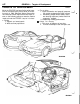
o-2 GENERAL - Targets of Development TARGETS OF DEVELOPMENT While the ECLIPSE has been finding wide acceptance as a compact sporty vehicle since its introduction early in 1989, Mitsubishi Motors Corporation has introduced further improvements with major accent on the following points to meet the market needs and make the ECLIPSE a top car in its class. l Styling 1. Organic and aerodynamic. 2. Wide and low proportions. N70ABOOAA Fun to drive 1.
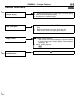
GENERAL - Design Features DESIGN FEATURES L b Unique styling l l l w New techniques Higher safety id Aerodynamic characteristics D t + l Forward extended cabin for roomy cabin and sporty styling Wide and low proportion body Aerodynamic oriented styling Chrysler-manufactured 2.0 lit.
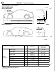
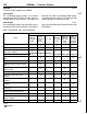
GENERAL - Technical Features TECHNICAL FEATURES BODY DIMENSIONS N70ADO2AA LJ External Dimensions 5, 6 * Internal Dimensions 00X0081 mm (in.) External dimensions Items No. New model Difference between previous and new models Overall Length 1 4,375 (172.2) -15 (-59) Overall Width 2 1,735 (68.3) 1,745 (68.7)*’ +40 (+1.57) +50 (+1.97)“’ Overall Height 3 1,295 (51.0) 1,310 (51 .6)*2 -11 (-.43) -4 (-. 15)*2 Wheelbase 4 2,510 (98.8) +40 (+1.57) Tread (front) 5 1,515 (59.
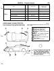
o-5 GENERAL - Technical Features No. New model Difference between previous and new models Head Room 8 (front) 9 860 (33.9) 0 Head Room 8 (rear) 10 785 (30.1) 0 Brake Pedal Room 11 940 (37.0) +15 (+.59) Hip Point Couple 12 635 (25.0) 0 Front Hat Room 13 1,080 (41.7) 0 Front Hip Point Couple 14 714 (28.
O-6 GENERAL - Technical Features ENGINE N70AEOOAA Two basic DOHC engines are available. ‘L) 420A Engine On non-turbocharged models, the Chryslermanufactured 2.0 lit. DOHC 16-valve engine increases domestic parts content. The engine and transaxle unit, unlike the conventional MMC engine, is arranged with the engine on the passenger side and the transaxle on the driver’s side.
T o-7 GENERAL - Technical Features id Items 1 Aims Smaller size and lighter weight Cooling fan controlled by ECM (Total Control System) Higher performance and efficiency Higher dependability and easier maintenance Resource and energy saving Less noise X Integrated control of A/T X Higher accuracy coolant temperature sensor X Crank angle sensor using Hall IC directly mounted to crankshaft X Cylinder block reinforced X Dual mode damper Air bypass valve position optimized Power steering be
O-8 GENERAL - Technical Features STEERING STABILITY, RIDE COMFORT AND ACTIVE SAFETY N70AFOOAA Multi-link Suspension for Four Wheels A multi-link suspension similar to the 1994 Galant’s, has been adopted for both the front and rear wheels. As a result, the straight line running characteristics and stability have significantly improved, assuring d outstanding directional stability without penalty on riding comfort.
O-9 GENERAL - Technical Features ABS ii N7OAFOlAA ABS is an option for all models to improve braking stability and safety. For the FWD vehicles, the 4-sensor, 3-channel configuration is adopted for independent control of the front right and left wheels and integrated control Electronic control unit (ECU) \ ABS warning light (Select Low control) of the rear wheels. For AWD vehicles, the 4-sensor, 2-channel configuration is adopted for Select Low control of all the front and rear wheels.
O-IO GENERAL - Technical Features PASSIVE SAFETY N70AGOOAA Supplemental Restraint System (SRS) An airbag module has been provided for both the driver’s and front passenger’s seats for safety of the driver and front passenger. The driver’s seat airbag module is mounted at the center of the steer- ing wheel, whereas the front passenger’s seat airbag ‘d module is mounted in the instrument panel above the glove compartment.
O-II GENERAL - Technical Features THEFT-ALARM SYSTEM N70AHOOAA For theft protection, this system is so designed that L the headlights go on and off and the horn is sounded intermittently for about three minutes when a locked door, hood or liftgate has been forced open without using a key. sr D Furthermore, the starter circuit is interrupted so that the engine may not be operated.
o-12 GENERAL - Technical Features HEATER AND AIR CONDITIONING The heater system uses a two-way-flow full-air-mix system that features high performance and low operating noise, and includes an independent face air blowing function and a cool air bypass function. Side defrosters have been provided in the door section to improve demister performance. For the rear seat, a semi rear heater duct has been provided for better heating.
GENERAL - Technical Features o-13 Use of maintenance-free parts i (1) Auto-lash adjusters have eliminated the need for adjustment of valve clearance. (2) An auto-tensioner has been adopted to eliminate the need for adjustment of the timing belt tension. (3) The improved mounting accuracies of the camshaft position sensor and crank angle sensor have eliminated the need for adjustment of ignition timing. (4) The plastic region angle method has been adopted for tightening the cylinder head bolts.
GENERAL - Vehicle Identification I\\ 1 VEHICLE IDENTIFICATION NOOACOOAB NWACWAB VEHICLE IDENTIFICATION NUMBER LOCATION ;L) The vehicle identification number (V.1.N) is located on a plate attached to the left top side of the instrument panel. VEHICLE IDENTIFICATION CODE CHART PLATE NOOACOlAB All vehicle identification numbers contain 17 digits. The vehicle number is a code which tells country, make, vehicle type, erc.
o-15 GENERAL - Vehicle Identification VEHICLES FOR CALIFORNIA Mitsubishi Eclipse 4A3AK34YOSE Model Code Engine Displacement Brand V.I.N. (except sequence number) 2.0 dm3 (122.0 cu.in.) [DOHC-MFI (420A)] l-----l D31 AMNJMLSM D31 AMRJMLSM D31 AMNHMLSM D31AMRHMLSM 4A3KF44YOSE i 4A3AK54SCiSE Mitsubishi Eclipse 4A3AL54SOSE Mitsubishi Eclipse 2.0 dm3 (122.0 cu.in.
O-16 GENERAL - Vehicle Identification : ENGINE MODEL ST2 PING NOOACO6AB 1. The engine model numbe M’ris stamped at the front side on the top edge of the cylinder block as shown in the LJ following. I Engine model I Engine displacement 420A II 2.0 dm3 (122.0 cu.in.) I 4G63 2.0 dm3 (122.0 cu.in.) 2. The 4G63 engine serial number is stamped near the engine model number, and the serial number cycles, as shown below. Engine serial number Number cycling AA0201 to YY9999 BAOOOl - - -w YY9999 3.
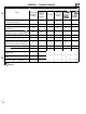
o-17 GENERAL - General Data and SDecifications GENERAL DATA AND SPECIFICATIONS NOOAHQOAB i/ 11 -I 6 L 1;; z;, GENERAL SPECIFICATIONS OOXQO73 D31A Model code MNJML4M MNJMLSM Vehicle dimensions mm (in.) Overall length MNHML4M MRHML4M MNGFL4M MNHMLSM MRHMLSM MNGFLSM 1,745 (68.7) 2 Overall height (Unladen) 3 1,295 (51 .O) Wheel base 4 2,510 (98.8) Front 5 1,515 (59.6) Rear 6 1,510 (59.4) Front 7 930 (36.6) Rear 8 935 (36.8) Minimum running ground clearance 9 145 (5.
GENERAL - General Data and Specifications <:AWD> Model code MNGFL4M MNGFLSM Items Vehicle dimensions Overall length D33A MRGFL4M MRGFLSM mm (in.) 1 4,375 (172.2) Overall width 2 1,745 (68.7) Overall height (Unladen) 3 1,310 (51.6) Wheel base 4 2,510 (98.8) Front 5 1,515 (59.6) Rear 6 1,510 (59.4) Front 7 930 (36.6) Rear 8 935 (36.8) 9 145 (5.7) degrees 10 12.2 degrees 11 16.
1-I id ENGINE CONTENTS ENGINE . . . . . . . . . . . . . . . . . . . . 2 ACCELERATION SYSTEM . . . . . . . . . . . . . . . . . . . . . . . . . . . 62 Accelerator Pedal and Accelerator Cable .................. 62 Auto-cruise Control System ............................... 63 BASE ENGINE . . . . . . . . . . . . . . . . . . . . . . . . . . . . . . . . . . . . . . . 3 Automatic Tensioner ......................................5 Camshaft ................................................
ENGINE - General Information ENGINE GENERAL INFORMATION N7MAO1M This 420A 2.0-liter engine is a product of Chrysler Corporation. It is not equipped with a turbocharger. MAJOR SPECIFICATIONS Specifications Items Total displacement Bore x Stroke cm3 (cu.in.) mm (in.) 1,996 (121.8) 87.5 (3.45) x 83.0 (3.27) Compression ratio 9.6 Camshaft arrangement DOHC Valve timing Intake Open Close Exhaust Open Close At 0.5 mm (.0197 in.) lift 1.3” BTDC 39.7” ABDC 36” BBDC 1.
ENGINE - Base Engine l-3 BASE ENGINE L CYLINDER HEAD N71ABOlAA der metal valve guides and seats. Integral oil galleys within the cylinder head supplies oil to the hydraulic lash adjusters, camshaft and valve mechanisms. Features a Dual Over Head Camshaft (DOHC) 4-valves per cylinder cross flow design. The valves are arranged in two inline banks.
ENGINE - Base Engine CONNECTING RODS The connecting rods are different from past designs because the manufacturing process has changed. The connecting rod is forged as one piece from powdered metal. The powdered metal is placed in a form that is slightly oversized and then sent to sintering furnace. It melts the powdered metal in the mold. The mold travels to a forging press where the rod is forged to the final shape. This is done while the rod is still warm, but not molten.
I-5 ENGINE - Base Engine CRANKSHAFT AND CAMSHAFT TIMING L This engine does not have broken-belt valve clearance. The reason for this design is to improve hydrocarbon emissions by eliminating valve pockets cut into the pistons that would normally provide this clearance. If the engine is rotated with the timing belt removed or the cam timing is set improperly, the valves will hit the pistons.
I-6 ENGINE - Base Engine Prior to installing tensioner on the engine, it is necessary to preload the tensioner plunger. This accomplished by installing the tensioner in a vise and slowly compressing the plunger. A tensioner plunger pin is installed through the body of the tensioner and plunger. When the tensioner is installed on the engine, it is necessary to preload the tensioner pivot bracket assembly with a torque wrench prior to securing the retaining bolts.
ENGINE - Base Engine OIL PAN I-7 NTlABO9AA The oil pan is a single-plane design, and is L constructed of stamped antiphon steel. comes equipped with the special sleeve that it used to prevent seal rollover. The rear main oil seal is a one-piece lip seal that requires a special sleeve for installation. A new seal Rear hain oil seal Bed plate CENOlOO OIL PUMP The oil pump is located at the front of the engine block, and is driven by the crankshaft.
I-8 ENGINE - Cooling System COOLING SYSTEM N7lAWOAA The cooling system is of the water-cooled, forced circulation type with the following features: l The water pump is mounted onto the front of the cylinder block, and is driven by the cogged side of the timing belt. The drive sprocket is sintered metal. The pump body is made of die cast aluminum; and a stamped-steel impeller is used to pump coolant through the engine. l The thermostat housing is located on the left front side of the engine.
ENGINE - Cooling System L SPECIFICATIONS Specifications Items Water-cooled pressurized, forced circulation with electrical fan Cooling method Radiator Type Thermostat Water pump Type Drive method Pressurized corrugated fin type Wax pellet type with jiggle valve Centrifugal impeller Timing belt CONSTRUCTION Radiator Reserve tank NT oil cooler (Dual pipe type) Radiator AtT oil cooler hose and pipe += ,-
I-10 ENGINE - Intake and Exhaust INTAKE AND EXHAUST tmAEooAA INTAKE MANIFOLD AND EXHAUST MANIFOLD The intake manifold is a two-piece aluminum casting, attached to the cylinder head with six bolts and two studs. This long branch fan design enhances low and midspeed torque. The exhaust manifold is made of nodular cast iron for strength and high temperatures. I EXHAUST PIPE N71AEOlAA The exhaust pipe consists of three parts: a front pipe, a center pipe, and a main muffler.
1-11 / ENGINE - Fuel System FUEL SYSTEM N?lAFOOAA The fuel system for 420A engine consists of electromagnetic fuel injectors, a fuel rail, a fuel pressure regulator, an electric motor-driven fuel pump, fuel filter and fuel tank.
I-12 ENGINE - Fuel System FUEL TANK The fuel tank is made of steel and is arranged under the rear seat floor for higher safety. The fuel tank has an internally mounted fuel pump assembly and fuel gauge unit. In addition, a fuel cut-off valve as- WlAFOlAA sembly is standard equipment on all vehicles. The fuel cut-off valve assembly prevents outflow of fuel even when the vehicle rolls over, assuring a higher measure of safety.
ENGINE - Control System I-13 CONTROL SYSTEM L GENERAL INFORMATION The fuel system for the 2.0 liter DOHC engine utilizes sequential multi-port fuel injection to deliver precise amounts of fuel to the intake manifold. Basic injector duration is controlled by a combination of signals from the front oxygen sensor and an air density signal from a MAP sensor. This vehicle uses a direct ignition system, eliminating the need for a distributor.
ENGINE - Control System SYSTEM BLOCK DIAGRAM N71AKOOAB Power-train control module (PCM) Sensors MAP Sensor Actuators b No. 1 injector -b Fuel injection control ---b No. 2 injector b b No. 3 injector Engine coolant temperature sensor -b b No. 4 injector Throttle position sensor Idle air control motor (stepper motor) - Idle air control Crankshaft position sensor + Ignition timing control -.
I-15 ENGINE - Control System MULTIPORT FUEL INJECTION (MFI) SYSTEM DIAGRAM *l *2 *3 ~4 +5 *6 *7 ~8 *9 l l l l l l l l Heated oxygen sensor (Front) Manifold absolute pressure sensor intake air temperature sensor Throttle position sensor Camshaft position sensor Crankshaft position sensor Engine coolant temperature sensor Knock sensor Heated oxygen sensor (Rear) Power supply Vehicle speed sensor A/C switch Park/Neutral position switch Power steering pressure switch Ignition switch-IG (J2 sense)
ENGINE - Control Svstem SENSORS N’HAKQ1AA MANIFOLD ABSOLUTE PRESSURE (MAP) SENSOR The powertrain control module (PCM) supplies 5 volts direct current to the MAP sensor. The MAP sensor converts intake manifold pressure into voltage. The PCM monitors the MAP sensor output voltage. As vacuum increases, MAP sensor voltage decreases proportionately. Also, as vacuum decreases, MAP sensor voltage increases proportionately.
ENGINE - Control System ENGINE COOLANT TEMPERATURE SENSOR The coolant temperature sensor provides an input i voltage to the power-train control module (PCM). The PCM determines engine coolant temperature from the engine coolant temperature sensor. As coolant temperature varies, the coolant temperature sensor’s resistance changes, resulting in a different input voltage to the PCM.
l-18 ENGINE - Control System The throttle position sensor (TPS) connects to the throttle blade shaft. The TPS is a variable resistor that provides the powertrain control module (PCM) with an input signal (voltage). The signal represents throttle blade position. As the position of the throttle blade changes, the resistance of the TPS changes. The PCM supplies approximately 5 volts to the TPS.
1-19 ENGINE - Control System L The camshaft position sensor attaches to the rear of the cylinder head. A target magnet attaches to the rear of the camshaft and indexes to the correct position. The target magnet has four different poles arranged in an asymmetrical pattern. As the target magnet rotates, the camshaft position sensor senses the change in polarity. The sensor output \ Rear of f3Ainder 7 / id switch switches from high (5.0 volts) to low (0.
l-20 ENGINE - Control System The notches generate pulses from high to low in the crankshaft position sensor output voltage. When a metal portion of the counterweight aligns with the crankshaft position sensor, the sensor output voltage goes low (less than 0.3 volts). When a notch aligns with the sensor, voltage spikes high (5.0 volts). As a group of notches pass under the sensor, the output voltage switches from low (metal) to high (notch) then back to low.
ENGINE - Control System I-21 The crankshaft position sensor mounts to the engine block behind the generator, just above the oil filter. AFU0073 HEATED OXYGEN SENSORS As vehicles accumulate mileage, the catalytic convertor deteriorates. The deterioration results in a i less efficient catalyst. To monitor catalytic convertor deterioration, the fuel injection system uses two heated oxygen sensors. One sensor upstream of the catalytic convertor, one downstream of the convertor.
I-22 ENGINE - Control System -Upstream The input from the upstream heated oxygen sensor tells the PCM the oxygen content of the exhaust gas. Based on this input, the PCM fine tunes the air-fuel ratio by adjusting injector pulse width. The sensor produces from 0 to 1 volt, depending upon the oxygen content of the exhaust gas in the exhaust manifold. When a large amount of oxygen is present (caused by a lean air-fuel mixture), the sensor produces voltage as low as 0.1 volt.
ENGINE - Control System VEHICLE SPEED SENSOR i L Vehicles with manual transaxle use a vehicle speed sensor. The sensor is located in the transaxle extension housing. The power-train control module (PCM) determines vehicle speed from the sensor input. The vehicle speed sensor generates 8 pulses per sensor revolution. These signals are interpreted along with a closed throttle signal from the throttle position sensor by the PCM.
I-24 ENGINE - Control System POWER STEERING PRESSURE SWITCH WIAKIOAA A pressure switch is located on the power steering unit’s body to signal periods of high pump load and pressure, such as those which occur during parking maneuvers. This allows the PCM to maintain target idle speed. To compensate for the additional engine load, the PCM increases airflow by adjusting the ‘i/i idle air control motor.
ENGINE - Control System KNOCK SENSOR The knock sensor threads into the side of the cylinder j block below the intake manifold. When the knock sensor detects a knock in one of the cylinders, it sends an input signal to the PCM. In response, the PCM retards ignition timing for all cylinders by a scheduled amount. I-25 N7lAK13AA Knock sensors contain a piezoelectric material which constantly detects engine knock vibration and sends an input voltage (signal) to the PCM while the engine operates.
1-26 ENGINE - Control System ACTUATORS AND CONTROL FUEL INJECTORS The 2.0L engine uses electrically operated top feed fuel injectors. The MFI relay (automatic shut down relay) supplies battery voltage to the fuel injectors. The PCM controls the ground path for each injector in sequence. By switching the ground paths on and off, the PCM fine-tunes injector pulse width. Injector pulse width refers to the amount of time an injector operates.
ENGINE - Control Svstem IGNITION COIL / I-27 N71AK22AA The coil assembly consists of 2 coils molded togeth- LI er. The coil assembly is mounted on the cylinder head cover. High tension leads route to each cylinder from the coil. The coil fires two spark plugs every power stroke. One plug is the cylinder under compression, the other cylinder fires on the exhaust stroke. Coil number one fires cylinders 1 and 4. Coil number two fires cylinders 2 and 3.
ENGINE - Control System FUEL PUMP RELAY The fuel pump relay supplies battery voltage to the fuel pump. The PCM controls the fuel pump relay by switching the ground path for the solenoid side of the relay on and off. The PCM turns the ground path off when the ignition switch is in the Off position. When the ignition switch is in the On position, the PCM energizes the fuel pump. If the crankshaft N71AK23AA position sensor does not the PCM de-energizes the one second.
ENGINE - Control System DUTY CYCLE EVAP PURGE SOLENOID The duty cycle EVAP purge solenoid regulates the i rate of vapor flow from the EVAP canister to the throttle body. The power-train control module operates the solenoid. During the cold start warm-up period and the hot start time delay, the PCM does not energize the solenoid. When de-energized, no vapors are purged. The PCM de-energizes the solenoid during Open Loop operation.
I-30 ENGINE - Control System ELECTRIC EGR TRANSDUCER The Electronic EGR Transducer (EET) contains an electrically operated solenoid and a back-pressure controlled vacuum transducer. The PCM operates the solenoid based on inputs from the multi-port fuel injection system. The EET and EGR valve are serviced as an assembly. When the PCM de-energizes the solenoid, vacuum does not reach the transducer. Vacuum flows to the transducer when the PCM energizes the solenoid.
ENGINE - Control Svstem 1-31 DIAGNOSTIC SYSTEM MALFUNCTION INDICATOR LAMP (MIL) id The PCM provides the ground path for the malfunction indicator lamp (Check Engine light in the gauge cluster on the instrument panel). The lamp comes on each time the ignition key is turned ON and stays on for a 3 seconds bulb test. The MIL lamp stays on continuously, when the PCM has entered a Limp-in mode or identified a failed emission component.
1-32 ENGINE - Control System In addition to illuminating the MIL lamp, a diagnostic trouble code (DTC) is stored in the Powertrain Control Module (PCM) and can be retrieved by a service technician using a diagnostic scan tool.
1-33 ENGINE - Control System DTC Identification, Maturation, and Erasure Once a test has been run, the diagnostic system ii determines whether the system has passed or failed. It must then determine if the test has failed the specified number of times required to illuminate the MIL. If not, the diagnostic system stores a maturing code. When this test is run again (on the next “trip”) the results are once again either pass or fail.
I-34 ENGINE - Control System Test condition N7lAK30AA There are a large number of tests waiting to be performed once the vehicle is stat-ted. It is the diagnostic system’s job to see that these tests are not only performed, but performed under the appropriate conditions. An additional job of the diagnostic system is to prevent false DTC’s from being stored.
ENGINE - Control System Diagnostic trouble code No.
I-36 ENGINE - Control System Diagnostic trouble code No.
ENGINE - Control Svstem MAIN MONITORS To meet OBD II requirements, the on-board diagnosL tic system must monitor the electrical input signals and the performance of output responses that can have an effect on vehicle emissions. In addition, there are several “main monitors” that review the result of system operations and their effect on emissions.
ENGINE - Control Svstem Operation Once it reaches its operating temperature of 572” to 662”F, the sensor generates a voltage inversely proportional to the amount of oxygen in the exhaust. This information is used by the PCM to calculate the fuel injector pulse width necessary to provide the critical 14.7 to 1 air/fuel ratio (stoichiometric).
ENGINE - Control System 02 Heater Monitor Background L In order for the 02 sensor to function properly, the 02 sensor must be heated to approximately 572“ - 662°F. To assist the 02 sensor in achieving this temperature, the O2 sensor is equipped with a Positive Thermal Coefficient (PTC) heater element. Both the upstream an downstream’s heater element is fed battery voltage any time the MFI relay is energized.
ENGINE - Control System Catalyst Monitor U71AK42AA Current vehicles use a three-way catalytic converter to reduce emission of harmful gases. The converters are referred to as three-way because they specifically address three pollutants (hydrocarbons, carbon monoxide, and nitrogen oxide) produced in the combustion chamber. The catalyst monitor uses a pair :j of inputs to indirectly measure just how effective the catalyst is at reducing emissions.
I-41 ENGINE - Control System A functioning converter stores oxygen so it can be used for oxidation of hydrocarbons (HC) and carbon monoxide (CO). The downstream sensor detects L a lower oxygen level in the exhaust than the upstream sensor. It indicates this by switching at a significantly slower rate than the upstream sensor.
1-42 ENGINE - Control System Fuel System Monitor Background N71AK43AA To control the level of undesirable emissions, the fuel system must be able to maintain strict control of the air/fuel ratio. Stoichiometry is the optimum air/fuel ratio, which is 14.7 to 1. At this point the best balance between the production of HC’s and CO’s (which drop as the mixture becomes leaner) and NOx (which increases as the air/fuel mix be- comes leaner) can be found.
I-43 ENGINE - Control System Operation The Power-train Control Module (PCM) varies the iipulse width of the fuel injectors to provide precise control of the air/fuel mixture. Wider pulse widths increase the volume of fuel delivered to the cylinders. The PCM uses the input from a number of sensors in its attempt to reach and maintain this air/fuel ratio. Manifold Absolute Pressure (MAP), and the 02 sensor have the greatest influence (authority) over injector pulse width.
1-44 ENGINE - Control Svstem To control air/fuel ratio feedback, the PCM uses short term correction and long term memory. Before the PCM can alter the programmed injector pulse width, it must enter closed loop operation. The requirements for closed loop operation are listed below: l Engine temperature exceeds 35°F l OS sensor is in the readv mode l AN timers have timed out -following the START to RUN transfer (The length of these timers varies with engine temperature) 35°F - 41 sec.
I-45 ENGINE - Control System If the oxygen sensor registers a rich or lean condition while driving in this cell, the cell will require updating L to aid in fuel control. The short term correction is used first. It starts increasing pulse width quickly (kick), then ramps up slowly. Each control is in inverse relation to the signal sent from the 02 sensor. For example: The 02 sensor switches lean to rich. Short term compensation kicks in lean, then ramps lean until the 02 sensor switches lean.
1-46 ENGINE - Control System Long term memory also has control over pulse width by being able to increase or decrease the pulse width stored in the cell by up to 25%. Long term memory is retained by the battery in the PCM, while short term correction is lost whenever the ignition is turned off. The long term memory works to bring the short term correction to the point where the average per- cent of pulse width compensation it provides in this memory cell is 0%.
ENGINE - Control System L Misfire Monitor Background I-47 WlAK44M Operation Misfire is defined by the California Air Resources Board as the lack of combustion in a cylinder due to absence of spark, poor fueling, compression, or any other cause. As a result, the air/fuel mixture will not burn, and during the exhaust stroke, it enters the exhaust system.
I-48 ENGINE - Control System The threshold for determining what amount of rpm change indicates misfire varies with engine speed and load. This is required because as engine speed increases or load decreases, the overall effect of a single cylinder misfire diminishes due to the momentum of the crankshaft. The misfire monitor contains an adaptive feature that can take into account component wear, sensor fatigue, and machining tolerances.
I-49 ENGINE - Control System Exhaust Gas Recirculation Monitor WlAK45AA Background L Exhaust Gas Recirculation (EGR) is a method of reducing oxides of nitrogen (NOx) emissions by introducing non-combustible exhaust gases into the combustion chamber. These gases absorb heat and reduce the high cylinder operating temperatures where NOx is most likely to occur. Lower combustion chamber temperatures result in lower NOx emissions. Upstream (primary) 02 sensor --. .
I-50 ENGINE - Control System Operation The EGR system consists of a vacuum solenoid, back pressure transducer and a vacuum operated valve. When activated, the solenoid allows vacuum to flow to the transducer. Negative exhaust backpressure allows manifold vacuum from the solenoid to vent to atmosphere. Positive exhaust backpres- sure causes the transducer diaphragm to modulate. This allows intake manifold vacuum to reach the L) EGR valve.
ENGINE - Control System The detect operation of the system, the solenoid is disabled and the 02 compensation control is monitored. If ttie EGR system is operating properly, turni ing’it off shifts the air/fuel ratio in the lean direction. I-51 02 sensor data should indicate an increase in oxygen in the exhaust gases and cause the short term control to shift rich. The amount of the shift indirectly monitors the operation of the system. EGR valve OFF Short term fuel compensation .
I-52 ENGINE - Control System DATA TRANSMISSION SYSTEM N71AKSOAA The power train control module (PCM) and transaxle control module (TCM) transfer control data to and from each other via a data communication system. The scan tool receives various tvpes of data from the transaxle control module through the data com- munication line and displays the data on the display.
ENGINE - Control System I-53 tmAW1 AA Bus+ and Bus- Circuits The data transmission system has two wires conL netted in parallel to the PCM and TCM. One circuit is Bus+, and the other is Bus-. For proper communication, the wires must be twisted together at 1.75” intervals. Twisting of the wires is intended to prevent switched-to-battery or switched-to-ground circuits from inducing electromagnetic interference (EMI) into the bus circuits.
1-54 ENGINE - Control System Biasing 5 volt supply Both bus circuits are biased (supplied voltage) to approximately 2.5 volts. The Bus+ and Bus- circuits ‘& are biased through a series circuit (see the illustration at left). The bus current travels from a 5 volt source through a 13k ohm resistor to Bus-, then through a 120 ohm termination resistor to Bus+, and then to ground through a 13k ohm resistor. Bus bias is j the voltage required to operate the bus.
ENGINE - Control System Bus Communication id 1-55 NllAK54AA Communication is based on voltage differential between the two bus wires. The differential occurs when two parts of the communication chip, the current sink and the current source, are used by the communication chip to control the bus current flow. Two different signal conditions can exist when the bus functions normally; there can be a “0” bit or a “1” bit.
1-56 ENGINE - Engine Electrical ENGINE ELECTRICAL N71AXOlM GENERATOR The generator is mounted on the right side of the engine, and is secured to the cylinder block with a pivot bracket and an adjustment bracket. The pivot bracket is secured with three mounting bolts. The case is grounded to the block, and three electrical connections are provided for charging system operation. STARTER MOTOR The output voltage of the generator is regulated by the power train control module.
I-57 ENGINE - Emission Control System EMISSION CONTROL SYSTEM L GENERAL INFORMATION There are three sources of vehicle exhaust emissions generated: the exhaust gases resulting from combustion, the blow-by gases generated within the crankcase, and the evaporative emissions generated from the fuel tank and other components of the fuel line.
1-58 ENGINE - Emission Control Svstem POSITIVE CRANKCASE VENTILATION SYSTEM The positive crankcase ventilation system is a systern for preventing the escape of blow-by gases from inside the crankcase into the atmosphere. Fresh air is sent from the air cleaner into the crankcase through the breather hose to be mixed with the blow-by gases inside the crankcase. The blow-by gas inside the crankcase is drawn into the intake manifold through the positive crankcase ventilation valve.
ENGINE - Emission Control System I-59 N71AP03AA EVAPORATIVE EMISSION CONTROL SYSTEM I During the cold start warm-up period and the hot The evaporative emission control system prevents start time delay, the PCM does not energize the the emission of fuel tankvapors into the atmosphere. id When fuel evaporates in the fuel tank, the vapors pass through vent hoses or tubes to the charcoal filled EVAP canister. The EVAP canister temporarily holds the vapors.
I-60 ENGINE - Emission Control System EXHAUST GAS RECIRCULATION (EGR) SYSTEM The exhaust gas recirculation (EGR) system lowers the nitrogen oxide (NOx) emission level. When the air/fuel mixture combustion temperature is high, a large quantity of nitrogen oxides (NOx) is generated in the combustion chamber.
1-61 ENGINE - Mount
I-62 ENGINE - Acceleration System ACCELERATION SYSTEM N77AWOQAA ACCELERATOR PEDAL AND ACCELERATOR CABLE The accelerator system is a cable and suspended pedal combination. The accelerator pedal side end of the cable is provided with a plastic bushing which effectively suppresses the noise that would result from direct contact of the cable and the accelerator arm.
ENGINE - Acceleration System AUTO-CRUISE CONTROL SYSTEM By using the auto-cruise control, the driver can drive at the speed he likes [in a range of approximately 56 to 137 km/h (35 to 65 mph)] without depressing the accelerator pedal. The actuator system consists of a reservoir assembly and a speed control assembly. The actuator is operated by intake manifold vacuum. I-63 N?‘lAWOlAA The control unit is incorporated in the engine control module.
I-64 ENGINE - General Information ENGINE GENERAL INFORMATION N7lSAOlAA This 4G63-DOHC engine with turbocharger is essentially the same as the one currently used for Eclipse. MAJOR SPECIFICATIONS Specifications Items Total displacement Bore x Stroke cm3 (cu.in.) mm (in.) 1,997 (121.9) 85.0 (3.35) x 88.0 (3.46) Compression ration 8.
ENGINE - Cooling System COOLING SYSTEM N710mmM The cooling system is of the water-cooled, forced l i circulation type with the following features: l l A small-size, high-performance radiator has been adopted for better cooling efficiency and less weight. Reduction in size of the automatic transaxle oil cooler had resulted in a lowered radiator position, which has permitted the “slant nose” design of the body.
1-66 ENGINE - Cooling System SPECIFICATIONS Specifications Items Water-cooled pressurized, forced circulation with electrical fan Cooling method Radiator Type Thermostat Water pump Type Drive method Pressurized corrugated fin type Wax pellet type with jiggle valve Impeller of centrifugal type Drive belt CONSTRUCTION Radiator fan assembly An(Air cooled) AIT oil cooler hose and pipe
I-67 ENGINE - Intake and Exhaust INTAKE AND EXHAUST i i INTAKE MANIFOLD AND EXHAUST MANIFOLD N71 BEOOM The intake and exhaust manifolds are basically the same as the once currently used. EXHAUST PIPE N71BEOlAA The exhaust pipe consists of three parts: a front pipe, a center pipe, and a main muffler with muffler cutter. It is mounted on the body via rubber hangers to minimize vibration transmission from the exhaust system to the body.
1-68 ENGINE - Fuel System FUEL SYSTEM N71 BFOOAA The fuel system of the 4G63 engine consists of electrcmagnetic fuel injectors, a fuel rail, a fuel pres- sure regulator, an electric motor-driven fuel pump, fuel filter and fuel tank.
ENGINE - Fuel System FUEL TANK I-69 N716FOlAA Features cAWD> L The fuel tank is the same as the one of the 420A l engine. (Refer to P. 1-12.) l The fuel tank is made from a high density polyethylene (HDPE) material and blow-formed into an integral tank. The tank has an internally installed pump and gauge assembly and pipe and gauge assembly. In addition, a fuel cut-off valve assembly is provided to prevent the leakage of the fuel that would occur when the vehicle rolls over.
I-70 ENGINE - Control System CONTROL SYSTEM N71 BKOOAA GENERAL INFORMATION LJ Except the following improvements, the MFI system is essentially the same as the one used on the 1994 4G63 2.0-liter DOHC engine. Major improvements I Remarks ECU control of the generator is adopted. Improves idling speed stability electric loads. ECM control of radiator fan and condenser fan is adopted. Basically the same as the one introduced on the 1994 Galant.
ENGINE - Control System SYSTEM BLOCK DIAGRAM N71 BKOOAB Sensors Engine control module (ECM) Volume air flow sensor I --b Fuel injection control 1 t I I --+I No. 3 injector b Engine coolant temperature sensor + Throttle position sensor -1 No.
1-72 ENGINE - Control System SYSTEM DIAGRAM injector r ala2 Evaporative emission purge solenoid +l Heated oxygen sensor (Front) *2 Volume air flow sensor *3 Intake air temperature sensor ~4 Throttle position sensor +5 Closed throttle position switch 6 Camshaft position sensor 217 Crankshaft position sensor *8 Barometric pressure sensor Sl Engine coolant temperature sensor +lO Knock sensor *II Heated oxygen sensor (Rear) ~12 Manifold differential pressure sensor 0 Power supply l Vehicle speed sens
I-73 ENGINE - Control System SENSORS NllBKQ1AA GENERATOR FR TERMINAL ii x Trio diode L---_------------------------------- Voltage regulator L Generator I 1. Engine control module 1 FU0887 Terminal FR of the generator inputs the ON/OFF state of the generator field coil to the engine control module. In response to this signal, the engine control module senses the generator output current, and drives the ISC servo according to the output current (electric load).
1-74 ENGINE - Control System ACTUATORS AND CONTROL N7l BK2OAA FAN MOTOR RELAY (RADIATOR AIR CONDITIONING CONDENSER) This relay controls the radiator fan and air conditioning condeser fan based on signals from the engine control module. GENERATOR G TERMINAL N71 BK2SAA The engine control module limits the generator output current by duty control of the continuity between generator terminal G and the ground.
ENGINE - Control System I-75 Voltage regulator Generator S terminal voltage: 12.3 V or more Engine control module 1 FUO890 When generator terminal G is short-circuited to the ground (let this be 0% duty), the Trt stays in the always OFF state. In this case, when the voltage at generator terminal S reaches 12.3 V, the power transistor is forced to OFF to adjust the output voltage to 12.3 V. Since the voltage is lower than charged battery voltage, practically no current flows from the generator.
I-76 ENGINE - Control Svstem COOLING FAN CONTROL WI BK60AA This sytem is similar to the one introduced on the 1994 Galant. Two transistors inside the engine control module control the radiator fan and the air conditioning condenser fan motor according to the engine coolant temperature and the vehicle speed. When the air conditioning switch and air conditioning pressure switch are ON, the fan motor rotate at high speed regardless of the engine coolant temperature and vehicle speed.
1-77 ENGINE - Control System GENERATOR CURRENT CONTROL N71EiK61AA During the period the engine is in operation, the engine ECM achieves duty control of the continuity L between generator terminal G and the ground. (In this case, the OFF duty of terminal G is controlled to equal the ON duty of the power transistor in the voltage regulator.
1-78 ENGINE - Control System DIAGNOSTIC SYSTEM DESCRIPTION OF OBD-II SYSTEM N716K7OAA The engine control module (ECM) monitors its input/ output signals. Some signals are monitored all the time, and others only under specified conditions. When an irregularity has continued for a specified time from when the irregular signal is initially monitored, the engine control module judges that a fault has occurred.
ENGINE - Control System l-79 Items indicated by Check Engine/Malfunction indicator lamp 2. After lighting the Engine Check/Malfunction indiNOTE 1. After detecting a fault, the engine control module cator lamp, the ECfvI turns it off when the ECM L (ECM) lights the Check Engine/Malfunction indidoes not detect the same fault in three consecucator lamp when it re-detects the same fault tive operations (provided that the operations in an operation following the next engine start.
ENGINE - Control System DIAGNOSTIC TROUBLE CODES The diagnostic items are shown in the following table. N710K71M ‘d Diagnostic trouble code No.
ENGINE - Control Svstem Diagnostic trouble code No.
ENGINE - Control System Item No. Inspection item General scan tool mode Scan tool mode X 59 Heated oxygen sensor (Rear) X 81 Long term fuel trim - Bank 1 X 82 Short term fuel trim - Bank 1 X 87 Calculated load value X 88 Fuel control state X - 95 Manifold differential pressure sensor X X I ACTUATOR TEST REFERENCE TABLE Item No. Inspection item 01 N71BK73AA Drive contents Cut fuel to No. 1 injector 02 Cut fuel to No. 2 injector - Injectors 03 Cut fuel to No.
I-83 ENGINE - Control Svstem MAIN MONITORS N710K40AA CATALYST MONITORING L (1) Monitoring method l Conversion efficiency is monitored on the FTP (Federal Test Procedure) basis. l Calculate a frequency ratio (RF) of output signals, oscillating from lean to rich or vice versa, from the front and rear 02 sensors according to the following equation. (2) Malfunction criteria If RF becomes larger than the predetermined value, a catalyst malfunction is indicated.
I-84 ENGINE - Control System OXYGEN SENSOR MONITORING (1) Monitoring method Detect the response time of front 02 sensor output signals when air-fuel ratio is changed intentionally from lean to rich or rich to lean under the hot steady state condition. EGR SYSTEM MONITORING (1) Monitoring method Operate EGR valve intentionally in the area of deceleration and detect the change of the EGR gas flow signal. FUEL SYSTEM MONITORING (1) Monitoring method A/F feedback compensation value is monil tored.
ENGINE - Engine Electrical / Emission Control System ENGINE ELECTRICAL I-85 N71BXOlM The generator, starter motor and ignition system iiare basically the same as the current ones. EMISSION CONTROL SYSTEM GENERAL INFORMATION l N71 EPOOAA The manifold pressure sensor is adopted to monitor the EGR system. l Other features of the system are essentially the same as the ones of the current system.
1-86 ENGINE - Emission Control System EXHAUST GAS RECIRCULATION (EGR) SYSTEM The exhaust gas recirculation (EGR) system lowers the nitrogen oxide (NOx) emission level. When the air/fuel mixture combustion temperature is high, a large quantity of nitrogen oxides (NOx) is generated in the combustion chamber.
I-87 ENGINE - Mount / MOUNT The mounts are basically the same as used on L 420A engine except that the arrangement of the WI BUOQAA engine and transaxle is reversed from that on 420A engine.
1-88 ENGINE - Acceleration System ACCELERATION SYSTEM N71 BWOOAA ACCELERATOR PEDAL AND ACCELERATOR CABLE The accelerator pedal and accelerator cable are the same as used on 420A engine. (Refer to P.l-62) AUTO-CRUISE CONTROL SYSTEM N71BWOlM By using the auto-cruise control, the driver can drive at the speed he likes [in a range of approximately 40 to 200 km/h (25 to 124 mph)] without depressing the accelerator pedal.
ENGINE - Acceleration System / Components and Functions L fi--,rrl SM.,:+,& ~“,,ll”l 2wvllC.
I-90 -- _ - ______- - ENGlNE - Acceleration Svstem , ------ Components Function Vehicle speed sensor It generates a pulse signal proportional to vehicle speed (revolving speed of the transaxle output gear). Control unit It receives signals from the vehicle speed sensor and each switch, and uses a micro-computer to control all functions of the auto-cruise control.
I-91 ENGINE - Acceleration System AUTO-CRUISE CONTROL UNIT The control unit is made up of the input interface circuit, micro-computer, constant voltage power supply circuit, micro-computer monitor circuit and output interface circuit. Signals from the vehicle speed sensor, throttle position sensor and each switch are input into the control unit. It processes them accord- ing to the program in the micro-computer memory and outputs control signals to the actuator.
2-1 POWER TRAlN CONTENTS AUTOMATIC TRANSAXLE . . . . . . . . . . . . . . . . . 35 Construction and Function . . . . . . . . . -40 Electronic Control System . . . . . . . . . . . . . . . . . . 73 Hydraulic Control System . . . . . . . . . . . . . . . . . . 53 Transaxle.. . . . . . . . . . . . . . . . . . . . . . . . . . . . . . . . 40 Sectional View . . . . . . . . . . . . . . . . . . . . . . . . . . . . . . .37 Specifications . . . . . . . . . . . . . . . . . . . . . . . . . . . . . . . .
POWER TRAIN - Clutch CLUTCH N72ZBWM The clutch is a dry single-disc, diaphragm type; hydraulic pressure is used for clutch control, The automatic centering type release bearing has ‘d been adopted. SPECIFICATIONS Items Non-turbo Clutch operating method Hydraulic type Clutch disc type Clutch disc facing diameter O.D. x I.D. Single dry disc type mm (in.) Clutch cover type Clutch cover setting load Clutch release cylinder I.D. Turbo 228 x 150 (9.0 x 5.9) 225 x 150 (8.9 x 5.
2-3 POWER TRAIN - Clutch CLUTCH CONTROL N722001AA A hydraulic system has been adopted for the control ii of the clutch. It offers the following features. 0 l A clutch fluid chamber and a compression type turnover spring have been adopted for better pedal feeling and less foot pressure.
2-4 Inter-lock POWER TRAIN - Clutch INTER-LOCK SWITCH 8WitCh N72ZB02AA The inter-lock switch is a switch provided in order to prevent sudden movement of the vehicle when the engine is started. d Thus, the starter motor will not be switched ON unless the clutch pedal is depressed, thereby switching OFF the inter-lock switch. NOTE The inter-lock switch is normally ON; it is switched OFF when the clutch pedal is depressed.
POWER TRAIN - Manual Transaxle MANUAL TRANSAXLE N72ZCOOAA b Three types of manual transaxle, F5MC1, F5M33, and W5M33 have been provided. F5MCl is a newly developed small and light-weight transaxle produced by Chrysler Corporation, while F5M33 and W5M33 transaxles are essentially the same as the conventional ones.
2-6 POWER TRAIN - Manual Transaxle SECTIONAL VIEW F5MCl 4 5 6 1. Reverse brake 2. 5th synchronizer 3. 5th speed gear 4. 4th speed gear 5. 4th synchronizer 6. 3rd synchronizer 7. 3rd speed gear 8. Reverse idler gear 9. 10. 11. 12. 13. 14. 15.
POWER TRAIN - Manual Transaxle 2-7 F5M33 6 ’ 18 - 19 1. Clutch housing 2. Input shaft 3. Bearing retainer 4. 1 st speed gear 5. 1 stPnd synchronizer 6. 2nd speed gear 7. 3rd speed gear 8. 3rd-4th synchronizer 9. 4th speed gear 10. 5th speed gear 11. 5th synchronizer 12. Reverse brake 13. Rear cover 14. 5th intermediate gear 15. Intermediate gear 16. Output shaft 17. Transaxle case 18. Differential drive gear 19. Differential 20.
2-8 POWER TRAIN - Manual Transaxle W5M33 8 16 v J 20 0 1. 2. 3. 4. 5. 6. 7. 8. 9. 10. 11. 12. 13. 14. 15. 16. 17. 18. 19. 20. 21. 22.
POWER TRAIN - Manual Transaxle CONSTRUCTION AND OPERATION Transaxle Case L The transaxle case assembly consists of front case housing, rear case housing and rear cover. Front 2-9 N72ZCOlAA case housing and rear case housing are made of cast aluminum. FRONT CASE HOUSING The clutch housing and front case are a one-piece aluminum casting for reduced weight. The clutch housing encloses the mechanical clutch assembly.
2-10 POWER TRAIN 1 Manual Transaxle Power Flow N72ZC02AA The F5MCl transaxle is a fully synchronized (except reverse), constant mesh transaxle. “Constant Mesh” means that all of the forward gears are constantly in mesh with each other. This eliminates the need to move gears together for engagement like reverse. The gears turn whenever the input shaft is supplying power; however, none of the gears transmits torque until a synchronizer is engaged.
POWER TRAIN - Manual Transaxle L NEUTRAL The input shaft supplies input power. First and second gears turn, but none of the synchronizers are engaged with speed gears. Because the synchroniz- ers are not engaged with any of the gears, power is not transferred to the output shaft.
2-12 POWER TRAIN - Manual Transaxle FIRST GEAR The 1-2 synchronizer sleeve moves forward to engage the clutch teeth on the first-speed gear. The power coming in the input shaft goes through the first-speed gear and into the synchronizer sleeve. - / 1-2 synchronizer sleeve / 1 st speed gear The sleeve turns the synchronizer hub and output shaft. The output shaft pinion gear turns the differen- ‘& tial ring gear. All other gears are freewheeling. The gear ratio for first is 3.54:1.
POWER TRAIN - Manual Transaxle L SECOND GEAR The 1-2 synchronizer sleeve moves rearward to engage the clutch teeth on the second-speed gear. The power coming in the input shaft goes through the second-speed gear and into the synchronizer 2nd speed gear 2-13 sleeve. The sleeve turns the synchronizer hub and the output shaft, The output shaft pinion gear turns the differential ring gear. The gear ratio for second I_ is 2.13:1.
2-14 POWER TRAIN - Manual Transaxle THIRD GEAR The 3-4 synchronizer sleeve moves forward to engage the third-speed gear clutch teeth. Input power goes through the input shaft, into the 3-4 synchronizer hub. The hub turns the synchronizer sleeve, third speed gear and the output shaft. The output shaft pinion gear turns the differential ring gear. The gear ratio for third is 1.
POWER TRAIN - Manual Transaxle FOURTH GEAR / The 3-4 synchronizer sleeve moves rearward to I/ engage the fourth-speed gear clutch teeth. Input power goes through the input shaft, into the 3-4 synchronizer hub. The hub turns the synchronizer 4th speed gear 2-15 sleeve, fourth speed gear and the output shaft. The output shaft pinion gear turns the differential ring gear. The gear ratio for fourth is 1.
2-16 POWER TRAIN - Manual Transaxle FIFTH GEAR The 5-R synchronizer sleeve moves forward to engage the fifth-speed gear clutch teeth. Input power goes through the input shaft, into the 5-R synchronizer hub. The hub turns the synchronizer sleeve, the fifth speed gear and the output shaft. The output shaft pinion gear turns the differential ring gear. The gear ratio for fifth is 0.81 :l AZ=-.
2-17 POWER TRAIN - Manual Transaxle L REVERSE GEAR The 5-R synchronizer sleeve and the reverse idler gear move rearward and engages with both input shaft reverse gear and the gear teeth around the outside of the l-2 synchronizer sleeve. Input power goes through the input shaft, across the reverse idler gear, and into the 1-2 synchronizer sleeve. The sleeve turns the synchronizer hub and output shaft. The output shaft pinion gear turns the differential ring gear in the reverse direction.
2-18 POWER TRAIN - Manual Transaxle Power Train Component INPUT SHAFT The front of the shaft is supported by a roller bearing in the front transaxle case housing. The rear of the shaft is supported by a sealed ball bearing in the rear case.
POWER TRAIN - Manual Transaxle 2-19 Input Shaft Bearing Assembly An input shaft bearing assembly is pressed into the front case of the transaxle. The assembly consists of the bearing housing, bearing, and seal. The seal prevents transmission fluid leakage into the clutch disc area. Individual components are not serviceable, if any of the components fail the entire assembly must be replaced. The clutch release bearing rides on the smooth round surface of the retainer during clutch operation.
2-20 POWER TRAIN - Manual Transaxle Input Shaft Assembly The input shaft transmits engine torque to the transaxle. The assembly consists of the input shaft, 3-4 and 5-R synchronizer assemblies, third, fourth and fifth speed gears, snap rings, caged needle bearings and thrust washers.
POWER TRAIN - Manual Transaxle First, second and reverse gears are machined on the shaft. Third, fourth and fifth speed gears ride L on caged needle bearings that rotate on the shaft journals. All of the forward gears are helical-type gears, and are in constant mesh with the output 2-21 shaft gears. The speed gears all have clutch teeth and cones, which are used to equalize shaft speeds during shifts.
2-22 POWER TRAIN - Manual Transaxle OUTPUT SHAFT The front of the output shaft is supported by a roller bearing that rides in the front transaxle case housing. The rear of the output shaft is supported by a sealed ball bearing in the rear case.
2-23 POWER TRAIN - Manual Transaxle Output Shaft Assembly The output shaft assembly transmits torque from i the input shaft to the differential ring gear. The front of the output shaft rides in a caged roller bearing supported by the front case. The rear of the shaft is supported by a sealed ball bearing located in the rear case. l-2 sleeve shaft 1 st speed gear \ Pinion gear 4th gear erse . .
POWER TRAIN - Manual Transaxle The assembly consists of the output shaft, l-2 synchronizer assembly, first and second speed gears, snap rings and needle bearings. First and secondspeed gears use caged needle bearings that rotate on the shaft journals. Third, fourth and fifth gears 1. 2. 3. 4. 5. 6. 7. 8. Output shaft First gear bearing First speed gear First gear stop ring Outer cone Inner cone l-2 synchronizer l-2 synchronizer snap ring are heated and pressed on the output shaft.
2-25 POWER TRAIN - Manual Transaxle REVERSE IDLER The reverse idler gear shaft is supported by the i front and rear cases.
2-26 POWER TRAIN - Manual Transaxle Reverse Idler Gear The reverse idler gear slides into mesh with the input shaft reverse gear and the gear teeth around the 1-2 synchronizer J sleeve. The idler gear allows the output shaft to turn in the opposite direction for reverse operation. The gear is supported by a shaft that is held in the front and rear cases.
POWER TRAIN - Manual Transaxle id DIFFERENTIAL ASSEMBLY The differential assembly is supported by two tapered roller bearings, one in the front case housing and the other in the rear case housing.
2-28 POWER TRAIN - Manual Transaxle Differential The F5MCl differential assembly is similar to previous transaxles, except the vehicle speed sensor drive gear is mounted on the differential case. The ring gear is an open center design and is bolted to the differential case. The pinion gear of the output shaft is in constant mesh with the ring gear which provides torque to the differential. 0475-051 - The differential case transfers torque from the ring gear to the differential side gears.
2-29 POWER TRAIN - Manual Transaxle Synchronizer L N72zco4AA Three synchronizer assemblies are used in the F5MCl transaxle. The 3-4 and 5-R synchronizers are mounted on the input shaft assembly and the 1-2 synchronizer is mounted on the output shaft assembly.
2-30 POWER TRAIN - Manual Transaxle -I Hub Sleeve Detent ball (3) SYNCHRONIZER COMPONENTS The synchronizer assemblies contain a sleeve, hub, struts, springs and detent balls. The sleeve has inner splines that ‘d slide on the hub and an outer radial slot that engages the shift fork. The hub has inner splines that engage the shafts and outer splines that the sleeve rides on. The outer hub splines have three slots, cut lengthwise, for the struts.
POWER TRAIN - Manual Transaxle 2-31 The assembly looks and functions much like a synchronizer. It consists of a stop ring, friction cone, shim, needle bearing and bearing race. If a shift to reverse is attempted before the clutch completely spins down (stops turning) the brake will stop the input shaft before the idler gear engages any other gear. The friction cone has lugs that fit into the case and holds the cone stationary. The 5-R synchronizer sleeve engages with the stop ring.
2-32 POWER TRAIN - Manual Transaxle SHIFT SELECTOR ASSEMBLY The shift selector assembly moves the appropriate shift fork based on the drivers selection. The assembly consists of the selector, shaft, housing, and pin. Selector housing 0475-030 (hT=fl cnlnrtnr The selector housing blocks the other shift forks and prevents a shift into two gears at the same time. The selector pivots in an arc to select the different shift forks.
POWER TRAIN - Manual Transaxle 2-33 When the 3-4 shift fork moves to the front of the transaxle, third gear is obtained. When it moves to the rear of the transaxle, fourth gear is obtained. 5th speed SIe 0475036 When the 5-R shift fork moves to the front of the transaxle, fifth gear is obtained. When the 5-R shift fork and the reverse shift fork move to the rear of the transaxle, reverse gear is obtained.
2-34 POWER TRAIN - Manual Transaxle TRANSAXLE CONTROL N72ZClOAA The shift cable and selector cable are equipped with bushings on their transaxle ends to absorb minute vibrations from the engine and transaxle. Also, the shift cable bracket on the shift lever end uses rubber to provides elastic support to the shift ;L) lever assembly thus minimizing vibration of the shift lever.
POWER TRAIN - Automatic Transaxle AUTOMATIC TRANSAXLE i; l l The automatic transaxle comes in three models: F4ACl for 420A-DOHC, F4A33 and W4A33 for 4G63-DOHC-T/C. F4ACl is electronically controlled 4-speed automatic transaxle newly developed for N72MOOAA l 420A-DOHC and manufactured by Chrysler Corporation. F4A33 and W4A33 are essentially the same as the previous models.
POWER TRAIN - Automatic Transaxle AWD FWD Drive system Self-diagnosis function Provided Fail-safe function Provided Data list function Provided Actuator forced drive function Provided ATF capacity Speedometer gear ratio dm3(qts.) 8.6 (9.1) 6.7 (7.
POWER TRAIN - Automatic Transaxle SECTIONAL VIEW 2-37 t472zDmAA F4ACl i SFAOl12 id 1. Damper clutch 2. Torque converter 3. Case 4. Oil pump 5. Input speed sensor 6. Underdrive clutch 7. Overdrive clutch 8. Reverse clutch 9. 2-4 clutch 10. Low/Reverse clutch 11. Output speed sensor 12. Planetary gear set 13. Output shaft gear 14. Transfer shaft 15. Transfer shaft gear 16. Defferential 17.
2-38 POWER TRAIN - Automatic Transaxle F4A33 TFA0540 1. Damper clutch 2. Torque converter 3. Oil pump 4. Front clutch 5. Kick-down brake 6. Rear clutch 7. Low/Reverse brake 8. Planetary gear set 9. 10. 11. 12. 13. 14. 15. 16.
POWER TRAIN - Automatic Transaxle W4A33 i 2 3 4 56 11 12 13 14 15 TFA0928 L’ 1. Damper clutch 2. Torque converter 3. Oil pump 4. Front clutch 5. Kick-down brake 6. Rear clutch 7. Low/Reverse brake 8. Planetary gear set 9. Transfer idler gear 10. Rear cover 11. Input shaft 12. Transfer drive gear 13. End clutch 14. Transfer driven gear 15. Center differential 16. Viscous coupling 17. Center shaft 18. Front output shaft 19. Front differential 20. Driven bevel gear 21.
POWER TRAIN - Automatic Transaxle CONSTRUCTION AND FUNCTION Transaxle r \ N722002AA I ransnllsslur I range switch Sole&d assembly 9321-415 l l The transaxle consists of the torque converter, oil pump, gear train and valve body. The torque converter incorporates the damper clutch and is of the 3-element, single stage, 2-phase type.
POWER TRAIN - Automatic Transaxle 2-41 TORQUE CONVERTER Torque converter clutch operation is controlled by the TCM through the solenoid assembly and valve body as mentioned. The clutch lining material is not bonded to either the piston or the torque converter cover in the F4ACl transaxle, it is free floating. When the clutch is not engaged, pressure is directed through the center of the input shaft to the front side of the piston.
2-42 POWER TRAIN - Automatic Transaxle CLUTCH All flve clutches in the F4ACl transaxle are applied hydraulically. Four of the clutches are released with belleville springs, and one is released with a coil spring. Three of the clutches supply input power to the planetary geartrain and are called input clutches.
POWER TRAIN - Automatic Transaxle 2-43 Underdrive Clutch L Underdrive clutch Rear sun gear Hub - j Underdrive clutch hub shaft Input clutch reiainer - The underdrive clutch is located in the front of the input clutch retainer. Line pressure is supplied to the clutch from the valve body, through passages in the case, oil pump and reaction shaft support. i The pressure then passes through a drilled passage in the input clutch hub and to the front side of the underdrive piston.
2-44 POWER TRAIN - Automatic Transaxle The overdrive clutch is the center clutch in the input clutch assembly. The clutch pack is held on the retainer, and the piston that applies the clutch is located around the outside of the retainer. A pressure plate in the rear of the clutch pack is used to compress the overdrive clutch when needed. Line pressure from the valve body is directed through passages in the case, oil pump housing and reaction shaft support.
POWER TRAIN - Automatic Transaxle 2-45 Holding Clutches 2-4 Clutch i; 2-4 clutch I Front sun gear hub Transaxle case / Lf Piston retainer Snao . Belleville spring Piston The 2-4 clutch is one of two clutches located in the rear portion of the transaxle case. This clutch sits behind the input clutch assembly. The 2-4 clutch/ piston retainer is in the front and held in place by a snap ring. The 2-4 piston is located inside the b 2-4 clutch/piston retainer.
2-46 POWER TRAIN - Automatic Transaxle Low/Reverse Clutch Front planetary carrier Low-reverse clutch . Transaxle case / Snap ring Reaction plate Separator plates v Clutch discs The second clutch, located in the rear of the transaxle case, is the Low Reverse (L/R) clutch. The UR clutch is located in the very back of the case and, as previously mentioned, shares the reaction plate with the 2-4 clutch. Behind the reaction plate is the clutch pack, belleville spring, L/R piston, and piston retainer.
POWER TRAIN - Automatic Transaxle 2-47 POWER TRAIN Planetary Geartrain Assembly Front sun gear assembly rear annulus assembly The entire planetary gear-train is located behind the input clutch assembly and is inside the 2-4 and UR clutch assemblies. The planetary geartrain con- 2-4 clutch Low-reverse Splined to #7 thrust #6 thrust gear front annulus assembly sists of two sun gears, two planetary carriers, two annulus (ring) gears, and one output shaft.
2-48 POWER TRAIN - Automatic Transaxle out sha I Lugs for parking pawl and output speed sensor annulus gear Rear Carrier Assembly The rear planetary carrier, front annulus (ring) gear and output shaft are all one assembly. The rear carrier assembly is responsible for providing all output power for the transaxle assembly. In other words, all output from the transaxle must go through the rear carrier.
POWER TRAIN - Automatic Transaxle 2-49 First Gear L Underdrive clutch applied (turns rear sun) In first gear range, torque input is through the underdrive clutch to the underdrive hub assembly. The underdrive hub is splined to the rear sun gear. When the underdrive clutch is applied, it rotates the underdrive hub and rear sun gear. The UR clutch is applied to hold the front carrier/rear annulus (ring gear) assembly. The rear sun gear drives the rear planetary pinion L gears.
2-50 POWER TRAIN - Automatic Transaxle Third Gear Underdrive clutch applied (turns rear sun) \. Overdrive clutch applied (turns front carrier/rear annulus) / In third gear, two input clutches are applied to provide torque input; the underdrive and overdrive clutches. The underdrive clutch rotates the rear sun gear, while the overdrive clutch rotates the front carrier/ rear annulus assembly.
POWER TRAIN - Automatic Transaxle 2-51 Reverse Gear Reverse clutch applied (turns front sun) In reverse, input power is through the reverse clutch. When applied, the reverse clutch drives the front sun gear through the overdrive hub and shaft. The UR clutch is applied to hold the front carrier/rear annulus assembly stationary. The front sun gear ii Low-reverse clutch applied (holds rear annulus front carrier) rotates the front carrier assembly pinions.
POWER TRAIN - Automatic Transaxle Differential case pinion Final Drive Gears and Differential The final drive gears include the transfer shaft which has a pinion gear on one end and the differential ring gear which is driven by the transfer shaft pinion gear. The ring gear is bolted to the differential case and when rotated drives the case. The case drives the differential gearset and in turn, the front axle shafts. The axle shafts then drive the front wheels.
POWER TRAIN - Automatic Transaxle Pump housing + ;;rpump Reaction shafi support I Seal rings (4) Hydraulic Control System OIL PUMP The oil pump is located in the pump housing inside the bell housing of the transaxle case. The F4ACl uses a crescent type gear pump. The inner gear is driven by the torque converter hub. Torque is supplied to the hub by the engine crankshaft through the flex plate and torque converter housing.
POWER TRAIN - Automatic Transaxle Valve Body Assembly Retainer Q- - Valves removed Valves installed 9x-439 The F4ACl has a relatively simple, cast aluminum valve body that uses only five valves. No governor pressure or throttle pressure is used to operate this valve body. These two pressures have been replaced by electronic signals from the output speed sensor and throttle position sensor. Shift valves have also been eliminated and replaced by the solenoid/ valves in the solenoid assembly.
POWER TRAIN - Automatic Transaxle Torque converter control valve Overdrive clutch 2-55 Regulator Valve The regulator valve has one function, to regulate or control hydraulic pressure in the transaxle. The pump supplies unregulated pressure to the regulator valve. The regulator valve controls or limits pump pressure. Regulated pressure is referred to as “line pressure”. The regulator valve has a spring on one end that pushes the valve to the right. This closes a dump (vent) to lower pressure.
2-56 POWER TRAIN - Automatic Transaxle Converter Clutch Control Valve The CC control valve has the job of controlling the back or “on” side of the torque converter clutch. When the TCM ener- “L) gizes the LR/CC solenoid to engage the converter clutch piston, the CC control valve and T/C control valves move to the left. The oil on the front or “off” side of the converter clutch piston is vented to the sump.
POWER TRAIN - Automatic Transaxle 2-57 Manual Valve The manual valve is operated by mechanical shift linkage only. Its job is to send line pressure to the appropriate hydraulic circuits and solenoids. The valve has three operating ranges or positions. The valve is shifted to the left position when Overdrive (OD), Drive (3) or Low (L) is selected. The valve is shifted to the middle position in both Park (P) and Neutral (N). The valve is moved to the right position when Reverse (R) is selected.
2-58 POWER TRAIN - Automatic Transaxle Underdrive clutch Underdrive solenoide (de-energized) 2-4/Law-reverse solenoid (energized) Orifice located in piston - 1 Reverse . . Torque converter apply pressure ~-~/LOW Reverse and Underdrive Solenoids When these two solenoids are not energized by the TCM, their check balls prevent venting of a clutch. In this position ‘d the check balls allow line pressure to reach the desired clutch.
POWER TRAIN - Automatic Transaxle ;. c I? D 2 Fluid venting from UD clutch (through Ul orifice and thermal valve) r 2-59 Thermal Valve The thermal valve is a bi-metallic shutter valve that helps control the venting rate of oil pressure in the underdrive clutch passage during release of the clutch. When the oil temperature is approximately 20 degrees Fahrenheit or less, the valve will be fully open to assist in venting oil past the Ul orifice.
2-60 POWER TRAIN - Automatic Transaxle VALVE AND SOLENOID HYDRAULIC CONTROL IN SELECTED GEAR RANGES Park/Neutral Hydraulically, this internal transaxle condition is In either of these gear selections, the transaxle has lube pressure. To provide smoother engagement, identical for both the Park and Neutral positions. the low/reverse clutch is pressurized, anticipating The only mechanical difference is that the parking a shift to a forward or reverse gear. The LWCC pawl is engaged in the Park position.
2-61 POWER TRAIN - Automatic Transaxle Rolling Neutral Above Eight MPH When the transaxle is in neutral, and vehicle speed i/’IS ab ove eight mph, all friction elements are disengaged to minimize or reduce drag and to avoid excessive element speed. The TCM de-energizes the LFUCC solenoid to vent the LR circuit. This configuration is ready to engage any forward gear, depending on vehicle speed and throttle position.
2-62 POWER TRAIN - Automatic Transaxle Reverse With the manual valve moved to the reverse position, line pressure is allowed through the manual valve directly to the reverse clutch and also through the 2-WLR solenoid to the low/reverse clutch. The regulator valve is designed to increase line pressure in the reverse gear range above the pressure that is normal for other ranges. This is done to increase clutch capacity.
2-63 POWER TRAIN - Automatic Transaxle Reverse Block Above Eight MPH Reverse gear will not engage if the TCM senses vehicle speed above eight mph. This is to prevent I/ damage that could occur if a driver accidentally puts the gear selector in “R” while rolling in any forward gear range. If the output speed sensor detects that the output shaft is spinning at a speed equal to or greater than eight mph, the TCM activates reverse block to protect the transaxle. The function is inoperable in “limp-in” mode.
,2-64 POWER TRAIN - Automatic Transaxle First Gear When any of the forward gear selections are made, line pressure is directed to all four solenoids. In first gear the TCM will energize the LWCC and 2-4/LR solenoids. This action applies the low/reverse and underdrive clutches. The forward gear position selected by the driver has no effect on manual valve position. Its location will be the same for all forward positions.
2-65 POWER TRAIN - Automatic Transaxle Second Gear / There are no solenoids energized in second gear. i With the solenoids de-energized, line pressure is directed to the 2-4 and underdrive clutches. Line pressure from the 2-4 clutch circuit is also directed to the solenoid switch valve, which moves the valve to the left. When the solenoid switch valve is moved to this position, it opens a circuit that can be applied by the TCM and LWCC solenoid for torque converter clutch engagement.
2-66 POWER TRAIN - Automatic Transaxle Second Gear EMCC When conditions allow for it, the TCM pulses or modulates the LWCC solenoid. This is called Electronically Modulated Converter Clutch (EMCC), as mentioned earlier. By pulsing or modulating the solenoid, the TCM can lower the line pressure that passes through the solenoid before reaching the converter clutch and torque converter control valves.
2-67 POWER TRAIN - Automatic Transaxle Direct Gear (Third) To shift into direct gear, the TCM energizes the L 2-4/LR and overdrive solenoids. This feeds line pressure to the underdrive and overdrive clutches. Line pressure from the overdrive clutch circuit is directed to an area between two large plugs at the end of the solenoid switch valve. This keeps the solenoid switch valve shifted to the left.
2-68 POWER TRAIN - Automatic Transaxle Direct Gear EMCC Direct gear EMCC is accomplished the same way as second gear EMCC. Whenever the TCM activates EMCC, it provides full line pressure from the regulator valve through the T/C control valve to the transaxle cooler to help improve transaxle cooling. For a review of EMCC operation, refer to Second ij Gear EMCC.
2-69 POWER TRAIN - Automatic Transaxle Direct Gear CC On In direct gear, when the torque converter clutch is L fully engaged it is called CC On. The solenoid and valve configuration for this position is the same as direct gear EMCC except the LR/CC solenoid is fully energized instead of pulsed or modulated. When the LR/CC solenoid is energized, it sends full line pressure to the ends of the T/C and CC control valves. Both the valves shift to the left.
2-70 POWER TRAIN - Automatic Transaxle Overdrive Gear (Fourth) The TCM energizes the underdrive solenoid which shuts off line pressure to the underdrive clutch. The TCM also de-energizes the 2-4 solenoid and allows the 2-4 clutch to engage. This shifts the transaxle into overdrive by allowing only the 2-4 and overdrive d clutches to be applied. OVERDRIVE LR = Low reverse UD = Underdrive R = Reverse AC = Accumulator PT = Pressure tap S = Solenoid OVERDRIVE LR(R-N-I) - 24 .
POWER TRAIN - Automatic Transaxle Overdrive Gear EMCC The EMCC function is the same in Overdrive as Lj I‘twas in the second and direct gear positions. For a review of EMCC operation, refer to second Gear EMCC. OVERDRIVE EMCC 24 = 2-4 clutch OD = Overdrive SW = Switch CC = Converter CL D = Dribbler V = Vent LR = Low reverse UD = Underdrive R = Reverse AC = Accumulator PT = Pressure tap S = Solenoid OVERDRIVE EMCC cc 1 LR=LOW REVERSE UD=UNDERCRIVE 24 =2-4 CLUTCH OD =OVERDRIVE .?‘_I-CI.
2-72 POWER TRAIN - Automatic Transaxle Overdrive Gear CC On In this position the torque converter clutch is fully engaged (CC On). The LWCC solenoid is fully energized as it was in the direct gear CC on position. For a review of the transaxle operation in the CC on position, refer to Direct Gear CC On. OVERDRIVE CC ON LR = Low reverse UD = Underdrive R = Reverse AC = Accumulator PT = Pressure tap S = Solenoid OVERDRIVE CC ON LR(R-N-l) r---l 2d 1(2-4 I) .
POWER TRAIN - Automatic Transaxle Electronic Control System / LJ INTRODUCTION TO THE ELECTRONIC CONTROL The advantage of using the electronic control system is more precise control over transaxle function. An added advantage of the system is that it can help the technician find a problem in a malfunctioning transaxle. The system can do this through what is called On-Board Diagnostics. The Transmission Control Module (TCM) continuously monitors its critical functions during normal operation.
2-74 POWER TRAIN - Automatic Transaxle Electronic control system Brake switch Map sensor I Speed contr Other vehicle -ontrol modules Scan tool (MUT-II) Transmission control module control relay Output speed sensor -f Input speed sensor Transaxle Transmission range and ParWNeutral position switches Four solenoids ---a----__ t 3 pressure switches TCM Direct Inputs The direct inputs connected to the TCM are battery feed, ignition run signal, cranking signal, throttle poskion sensor signal, engine sp
POWER TRAIN - Automatic Transaxle 2-75 TRANSMISSION CONTROL MODULE (TCM) The Transmission Control Module (TCM), is the brain of the transaxle. It receives information from several inputs for making decisions on how the transaxle should function. Some of the information is used only by the TCM, and some of the information is shared with other components through the CCD bus. The CCD bus is simply a communication link between the TCM and other electronic components on the vehicle.
2-76 POWER TRAIN - Automatic Transaxle (3) Self Diagnostics Another feature of the TCM is that it helps the technician find a problem within a malfunctioning transaxle or control system. It can do this through self-diagnostics. When something goes wrong with any of the (4) Diagnostic Trouble Codes In addition to sensing electrical malfunctions, the TCM can also detect some hydraulic and mechanical malfunctions that also produce diagnostic trouble codes. Each code represents a different malfunction.
POWER TRAIN - Automatic Transaxle L TRANSMISSION CONTROL MODULE INPUTS AND SENSORS at what information it receives and how it uses that The TCM must depend on receiving information ’ in order to control shift quality. Let’s take a look information. Direct Battery Voltage There is constant battery voltage supplied to the TCM, even when the ignition is turned off. This battery supply is responsible for keeping the TCM’s memory alive.
POWER TRAIN - Automatic Transaxle here End of the sensor counts I tor attaches here g+j h+spe&-j 1 1 I Park/N&tral \ position switch Input Speed Sensor The input speed sensor gives information, to the TCM, on how fast the torque converter turbine is spinning. The sensor is located on the front side of the transaxle case, close to the bell housing.
POWER TRAIN - Automatic Transaxle Solenoid and 2-79 Pressure Switches The low/reverse, overdrive, and 2-4 pressure switches are all located in the solenoid pack assembly. All three switches send the same type of information to the TCM. These switches tell the TCM if there is hydraulic pressure in their particular circuits. The pressure switches do not tell the TCM how much pressure is in the circuit. They just indicate that pressure exists or does not exist.
2-80 POWER TRAIN - Automatic Transaxle Engine Speed The TCM uses both direct engine speed input from the crankshaft position sensor or distributor and calculated engine speed ‘Lj input from the PCM over the CCD bus. The direct input is required to provide immediate information for use by the TCM control logic. The slower CCD engine speed data is used by the TCM fail-safe logic to confirm that the direct engine speed data is valid.
POWER TRAIN - Automatic Transaxle 2-81 TRANSMISSION CONTROL MODULE OUTPUT SIGNALS AND DEVICES / The TCM takes the input information from the sensembly. The following items are output components sors, evaluates the input, then uses it to control operated by the TCM. L the transmission control relay and the solenoid as- Transmission Control Relay The instant the ignition is turned on, the TCM performs a self-test to determine if its internal electronic circuits are all working properly.
2-82 POWER TRAIN - Automatic Transaxle Vehicle Speed Signal The vehicle speed signal is sent as a direct input from the TCM to the PCM. This system is called electronic pinion. The output speed sensor signal is sent to the TCM and used as the vehicle speed signal. The F4ACl does not use a vehicle speed sensor as in past transaxles.
POWER TRAIN - Automatic Transaxle : L 2-83 TRANSMISSION CONTROL MODULE OPERATION Introduction What does it do and how does it know? You have probably asked yourself this question more than once as you pondered some transaxle problems. This is really a very complex question. Just stop and think about it for a minute.
POWER TRAIN - Automatic Transaxle Random Access Memory (RAM) One of the start routine checks is to verify that the data storage bits in each RAM location are functioning properly. RAM is a form of memory that can Read Only Memory (ROM) A ROM check also occurs during the start routine. The check is to verffy that all of the data stored in the ROM is valid. ROM is a permanent memory be written to and changed, as well as read from. Code 17 is reported with a failure of RAM.
POWER TRAIN - Automatic Transaxle SLP T42 T41 P R N D 2 L Tl T2 CL OP OP OP OP CL OP OP CL OP OP OP CL CL CL CL OP OP OP CL OP CL OP OP OP OP CL OP OP OP OP OP TO1 TO3 Shift Lever Position (SLP) Logic The primary function of SLP logic is to provide safe, continuous, but limited operation of the transaxle with the presence of an invalid or transition input code. The SLP logic function screens the input codes from the switches and provides an SLP output signal to control actual gear selection.
POWER TRAIN - Automatic Transaxle Transaxle Temperature The transaxle temperature operating range is based ona predicted fluid temperature which is calculated from a combination of inputs. The predicted fluid temperature is continually updated and retained in memory for 20 minutes after the ignition switch is turned off.
POWER TRAIN - Automatic Transaxle L I L Inhibits and Shift Action Summary For neutral (N) and reverse (R) there are no logic inhibits placed on SLP changes into or out of either neutral or reverse. These gear ranges are shift lever controlled modes of operation. Neutral and reverse must be immediately provided for. Also, a reverse block function is used at speeds over approximately 10 - 15 mph by continuously venting the Low/Reverse (L/R) clutch.
POWER TRAIN - Automatic Transaxle Adaptive Coast Down Scheduling Adaptive scheduling may result in delayed 4-3 or 3-2 downshifts under certain conditions in order to maintain good shift quality. Speed Control When the transmission temperature range is either warm or hot, the 4-3 shift pattern is modified to kickdown earlier if a cruise control “on” signal is received over the CCD bus from the PCM.
POWER TRAIN - Automatic Transaxle Types of EMCC Logic No EMCC Logic -This is when the torque converter L clutch is off. Partial EMCC Logic - This logic will modulate the LB/CC solenoid (duty-cycle) to obtain partial torque converter clutch application.
2-90 POWER TRAIN - Automatic Transaxle 2s 2ND I 1ST q = In-gear logic n = Shift logic 1 S, 2s = Shift schedule output 1 ST, 2ND = Speed ratio shift complete signal 1s Shift Logic Selection The purpose of the Shift Logic Selection program is to activate the appropriate “shift logic” so that the “in-gear logic” condition d matches the gear called for by the shift schedule (driver selected gear, throttle position). Imagine that the TCM must always be in one of the logic boxes at any given time.
POWER TRAIN - Automatic Transaxle 1 ‘121 )9( 421 101 = In-gear logic 1 S, 2S, 3S, 4S, RS = Shift schedule output lst, 2nd 3rd, 4th, Rev. = Speed ratio shift = Shift logic complete signal q i d Shift Execution Logic As with most automatic transmissions, including the F4ACl gearset, two clutches must be applied to provide an operating gear range. One of the applied clutches must be an input clutch driven by the torque converter, such as the Reverse, the Underdrive, or the Overdrive clutches.
POWER TRAIN - Automatic Transaxle Solenoid Driver Logic Electronic solenoid valves connect the clutches to either a hydraulic source or a vent. Solenoid coils, when energized, exert force on a push rod which in turn opens or closes a ball valve and/or vent. To increase efficiency, the current through the solenoid coil is pulse-width modulated. The microcomPulsing the Solenoids The Full ON pulse time is normally around 8 milliseconds and provides rapid pull-in response time.
POWER TRAIN - Automatic Transaxle Clutch Solenoid id OD ON ON LRJCC ON ON UD OFF ON 24lLR~ OFF ON J 2-93 Solenoid and Element Logic Since both normally-ON and normally-OFF solenoids are used, the following logic is recognized by the TCM. The LWCC solenoid controls the LR clutch in first gear, Neutral, and Park and controls the Converter clutch (CC) in second, third, and fourth gears. The solenoid switch valve position determines which clutch (LR or CC) the solenoid will control.
2-94 POWER TRAIN - Automatic Transaxle Solenoid Switch Valve Control Logic This valve protects against the inadvertent application of LR clutch in second, third, or fourth gear ranges. When shifting to first gear, the Solenoid Switch Valve (SSV) must be in the downshifted position or action must be taken to shift the SSV into the downshifted position. As long as any of three pressures (2-4, OD, or UD) are greater than X% of line pressure (X = 60% for UD and OD, 70% for 2-4), the SSV will remain upshifted.
POWER TRAIN - Automatic Transaxle Normal Shutdown Routine When the ignition switch is turned off (column lock, i key out position), the TCM will go through a specific shutdown routine. For the first twenty minutes after ignition off, the CPU remains in the “awake” mode. In tills off-time tracking mode, the TCM continues to perform certain functions such as predicting fluid temperature calculations.
2-96 POWER TRAIN - Automatic Transaxle Immediate Shutdown -To cause an immediate shutdown to occur, all solenoids are turned off at the same time. To cause an immediate shutdown the transmission control relay is opened at the time of the failure. Default to second gear will take place from first, third, or fourth gear. The immediate shutdown may result in clutch overlap at low to moderate throttle angles and a temporary engine flare with heavier throttle angles.
POWER TRAIN - Automatic Transaxle DIAGNOSTIC FUNCTION CHART Diagnostic trouble code No.
POWER TRAIN - Automatic Transaxle Diagnostic trouble code No.
POWER TRAIN - Automatic Transaxle 2-99 TRANSAXLE CONTROL / l L l N72ZDlbA To prevent abrupt starting made through mistakes in selector lever operation, automatic transaxle fail-safe mechanism (key interlock system, shift lock system and reverse “R” position warning system) has been adopted.
POWER TRAIN - Automatic Transaxle A/T FAULTY OPERATION PREVENTION MECHANISM Shift Lock System d Unless the brake pedal is being depressed, the selector lever cannot be shifted to any other position from the “P” position. Moreover, if the ignition key is in “LOCK” position or if the key has been removed, the selector lever cannot be shifted to any other position from “P” position even if the brake pedal is depressed. 1.
POWER TRAIN - Automatic Transaxle Revolving cam nder Slide lever Slide lever 2-101 Key Interlock System Unless the selector lever is in ‘P” position, the ignition key cannot be turned to the “LOCK” position, and the key cannot be removed. The key interlock device installed in the inside of the ignition key cylinder consists of the slide lever, cam lever and revolving cam. The slide lever is connected to the key interlock cable.
POWER TRAIN - Automatic Transaxle Removed section Select lever 3. WHEN THE IGNITION KEY IS PULLED OUT Selector Lever is a Position Other than “P” Position Lock cam turns in the direction of the arrow shown in the illustration and stays there. As a result, the key interlock cable is caught on lock cam and the cam lever inside the ignition key cylinder is turned in the direction of the arrow shown in the illustration (it is in the removed section of the revolving cam).
2-103 POWER TRAIN - Propeller Shaft PROPELLER SHAFT L N72ZEOOM The AWD vehicles have a 3-section, 4-joint type propeller shaft with center bearings. The center bearing, provided with front and rear oil seals, is compact, lightweight and has excellent vibration and noise characteristics, In keeping with adoption of the compact center bearing, the insulator for installation of the bearing to the body has been changed in shape to further reduce vibration.
2-104 POWER TRAIN - Front Axle FRONT AXLE N72ZFOOM The drive shaft use the BJ-TJ constant velocity joint combination which offers high power transmission efficiency, ensures smooth inward-outward sliding movement and transmits less engine vibration during idling. FEATURES l l l l l The front hub has a press-fitted unit bearing. The unit bearing consists of inner and outer races and an oil seal. It features low rotating resistance and higher protection against mud.
2-105 POWER TRAIN - Rear Axle REAR AXLE N72ZGOOAA (-, The rear axle is of a design having axle shafts with press-fitted unit bearings. FEATURES l l i The unit bearing consists of inner and outer races and an oil seal for lower rotating resistance and higher protection against mud. The rear axle shaft bolted to the knuckle improves serviceability. Rear axle shaft l ABS equipped vehicles have a wheel speed detection rotor on the rear axle shaft and a speed sensor on the knuckle.
2-106 POWER TRAIN - Rear Axle REAR AXLE N72ZHWM The constant velocity joint on the differential side of the drive shaft is a TJ type one which ensures smooth inward-outward sliding movement. A BJ type joint is used on the hub side. FEATURES l l l The drive shaft is spline coupled on the different side and serration coupled on the hub side, eliminating the need for an axle shaft to allow for simplicity around the hub. The R.H.
2-107 POWER TRAIN - Rear Axle cAWD> DIFFERENTIAL / L N72ZHOlAA The differential uses a low frictional torque bearing and oil seal to provide improved power and fuel efficiency. For better cooling of the differential during highspeed operation, the differential carrier has cooling fins. In addition, VCU type LSD is used on some models.
2-108 POWER TRAIN - Rear Axle DIFFERENTIAL SUPPORT The front of the differential carrier is elastically supported by the bushing of the differential mount brack- N72ZH02AA et assembly, and its rear is supported by the bushings on the rear cross member.
, 3-i I / L CONTENTS ANTI-LOCK BRAKE SYSTEM (ABS) . . . . . . . . . . . . . . . . . . . . ..*....a..... PARKING BRAKES . . . . . . . . . . . . . . . . . . . . . . 44 ABS Electrical Circuit Diagram . . . . . . . . . . . . . . 46 ABS Hydraulic Function Schematic . . . . . . . . . . 47 Actuator . . . . . . . . . . . . . . . . . . . . . . . . . . . . . . . . . . . 50 Electronic Control Unit (ECU) . . . . . . . . . . . . . . . 51 Sensor . . . . . . . . . . . . . . . . . . . . . . . . . . . . . . . .
DRIVE-CONTROL COMPONENTS - Suspension SUSPENSION N732000AA Both the front and rear suspension are a new multilink design which is the result of the development effort for the best compromise between high-level steering stability and ride. FEATURES N73ZBOlAA 1. New multi-link design 2. Increased caster angle, reduced kingpin angle (front) 3. Reduced initial camber (front) 4. Adoption of virtual kingpin axis scheme 5. High-mounted front and rear upper arms 6. Increased rigidity of front cross member 7.
3-3 DRIVE-CONTROL COMPONENTS - Front Suspension FRONT SUSPENSION i - N73ZCOOAA FEATURES The front suspension is similar to that introduced on the 1994 Galant. It is a multi-link structure featuring two lower arms by which an ideal virtual kingpin &?x==Y axis is formed. In addition, the upper arms have been raised above the tire level to improve both directional stability and ride.
DRIVE-CONTROL COMPONENTS - Front Sumension 3-4 SPECIFICATIONS items Medium price M/T High price A/T Suspension type Wheel alignment Camber Caster Toe-in M/T A/T Multi-link type -0”05’ Ik 30’ 4”40’ f 1030’ 0+3(Of.12) mm (in.) Coil spring Wire dia. x O.D. x free length mm (in.) Identification color Spring constant N/mm (Ibs./in.) -0”20’ f 30’ 4”40’ f 1030’ 0+3(Of.12) 13.1 x71.1 111.1 x 309.5 (52 x 2.80 4.37 x 12.19) White + Pink 13.2x71.2111.2 x 315.5 (52 x 2.80 4.38 x 12.42) White + Gray 12.
3-5 DRIVE-CONTROL COMPONENTS - Front Suspension CONSTRUCTION A high mounted upper arm and two lower arms id act like a double-wishbone arrangement. In this arrangement, a virtual kingpin axis is formed on the line connecting the external vertex of the upper arm triangle and the point where the lines extended from the two lower arms intersect. This construction provides the following advantages: l A negative offset geometry is established which assures better stability during braking.
3-6 DRIVE-CONTROL COMPONENTS - Front Suspension Double Wishbone Suspension OPTIMIZED VIRTUAL KINGPIN AXIS POSITIONING In a double-wishbone type suspension, the lower point the kingpin axis passes through is the joint between knuckle and d lower arm (point A in the illustration at the left).
DRIVE-CONTROL COMPONENTS - Front Suspension i Vehicle moving direction The direction The direction toward which the wheels tend to pull P$Ti, / j-/T: ynt Fc Large; road surface resistance I 12AOO3 , L 3-7 Effects of Negative Offset Geometry (1) When the brake pedal is depressed on a running vehicle with one wheel on a slippery surface, a force is produced which causes the vehicle to pull toward the side with larger road surface resistance (to the right in the case illustrated at the left).
3-8 DRIVE-CONTROL COMPONENTS - Front Suspension Effects of Reduced Wheel Center to Kingpin Axis Offset (1) When the vehicle is accelerated or decelerated, (3) In the multi-link suspension, the offset is as or when it goes over a projection on road without small as about a third of that in a strut type d braking, the traction acting on the wheel center suspension and about one half of that in a generates a moment around the kingpin axis double-wishbone suspension.
DRIVE-CONTROL COMPONENTS - Front Suspension HIGH-MOUNTED UPPER ARM When a side force or any other force acts on the i tire in a way to change its camber angle, the degree of the rigidity that supports the tire depends on the hardness of the upper and lower arm rubber bushing. If the hardness of the bushings is increased, however, a larger friction will result during up-and-down motion of the suspension, leading to a poorer ride.
340 DRIVE-CONTROL COMPONENTS - Front Suspension VARIATION IN CAMBER DURING CORNERING When the steering wheel is turned, camber varies as shown below because of increased caster angle and reduced kingpin angle. On the vehicle with multilink suspension, the change in “camber to ground” caused by the body rolling during cornering is small by the same action as the one experienced in a double-wishbone suspension.
DRIVE-CONTROL COMPONENTS - Rear Suspension REAR SUSPENSION L 3-11 N73ZDOOAA FEATURES The rear suspension is similar to that introduced on the 1994 Galant. It is a new development in multi-link design. By properly arranging the individual control arms and properly selecting their bushings for well balanced rigidity, a best compromise between high-level directional stability and riding comfort has been realized in the suspension.
DRIVE-CONTROL COMPONENTS - Rear Suspension 3-12 SPECIFICATIONS Items Medium price Suspension type Wheel alignment Toe-in Camber mm (in.) Identification color Spring constant N/mm (Ibs./in.) Shock absorber We Stroke mm (in.) Damping force [at 0.3 m/set. (.9 ft./set.)] Expansion N (Ibs.) N (Ibs.) NOTE *l: Vehicles with 14-inch wheels : Vehicles with 16-inch wheels (3) *4: M/T Premium price Multi-link type Coil spring Wire dia. x O.D. x free length mm (in.
DRIVE-CONTROL COMPONENTS - Rear Suspension 343 CONSTRUCTION A high-mounted upper arm and a combination of ’ i lower arm and trailing arm act like a double-wishbone configuration having a virtual kingpin axis. This construction, like that of the front suspension, provides the following features: l Small offset between the virtual kingpin axis and wheel center provides better directional stability. l The high-mounted upper arm helps improve the tire supporting rigidity and riding comfort.
DRIVE-CONTROL COMPONENTS - Rear Suspension 3-14 VARIATION IN TOE ANGLE ON TURNS When the vehicle rolls as it makes a turn, the toe geometry changes as shown by the characteristics curve at the left under d the effect of the toe control arm action. Also, under the side forces that are generated during a turn, the toe angle of the outer wheel changes in such a way that the toe-in state will be maintained thanks to the balance in rigidity of the individual arms’ bushings properly selected for that effect.
DRIVE-CONTROL COMPONENTS - Wheels and Tires L 3-15 WHEELS AND TIRES N73ZGWAA SPECIFICATIONS Premium price Items Medium price High price AWD FWD A/T Wheel Tire size Wheel type Wheel size Amount of wheel offset mm (in.) Tire inflation pressure kPa (psi.) Front Rear Pl95/7ORl4 90H Steel type Aluminum type** 14 x 5.5JJ P205/55Rl6 89H Steel type Aluminum type*’ l6x6JJ P205/55Rl6 89V 46 (1.8) 220 (32) 200 (29) Spear wheel Tire size Wheel size L Amount of wheel offset mm (in.
3-16 DRIVE-CONTROL COMPONENTS - Power Steering POWER STEERING N73ZEOCjAA All models come standard with an engine speed sensitive power steering system. ‘d FEATURES N73ZEOTAA Engine speed sensitive power steering 1. Impact absorption mechanism 2. Supplemental Restraint System (SW) Double-lip oil seals used in power cylinder l l The 4-spoke type steering wheel with SRS unit is adopted on all models.
DRIVE-CONTROL COMPONENTS - Power Steering / id 3-17 CONSTRUCTION Steering wheel Steering column assembly Coolet! pipe Cooleipipe Al 3X0225
3-18 DRIVE-CONTROL COMPONENTS - Power Steering STEERING WHEEL The steering wheel have the following features to provide excellent maneuverability and stability. l The steering wheel has been specially designed for improved maneuverability and good view of meters. Some model versions come with a l steering wheel with auto-cruise control switches on it. Ij The air bag incorporated in the steering wheel provides the driver with additional protection against the shock from a front-end collision.
DRIVE-CONTROL COMPONENTS - Power Steering 3-l 9 SHOCK ABSORBING STRUCTURE (1) When the vehicle collides with something and there is a load added to the steering shaft from the gear box (primary shock), the polyacetal resin in the joint assembly is separated, and the shaft assembly slides into the pipe assembly, absorbing the shock load.
J DRIVE-CONTROL COMPONENTS - Power Steering 3-20 @ When a shock load is applied to the steering wheel, the upper column slides forward. At the same time, the bellows of the steering shaft L) are deformed. During this process, the shock load is absorbed by the friction between the lower column and the inside surface of the steering bushing attached to the upper column.
DRIVE-CONTROL COMPONENTS - Power Steerina 3-21 STEERING GEAR AND LINKAGE (1) The bearings used in the rack end and the tie rod end ball joints are one-piece type bearings which ensure higher rigidity. Tie rod end Bear:ng 13x0014 Lip I I (2) Double-lip type oil seals are used in the power cylinder to improve the reliability. Al 3X0226 (3) The pinion shaft side of the steering gear and linkage assembly has been secured directly to the cross member for higher rigidity and positional accuracy.
3-22 DRIVE-CONTROL COMPONENTS - Brakes BRAKES N73ZLOOAA The brake system offers high dependability and durability along with improved braking performance and brake sensitivity. d FEATURES /1 bm,mrov&b~king 1. The 4-wheel anti-lock brake system (4ABS) prevents skidding that may result from locked wheels, thereby assuring safe braking. 2. For some models, 2-piston type ventilated disc brakes have been adopted for front wheels to provide more stable braking and better braking feel. 3.
DRIVE-CONTROL COMPONENTS - Service Brakes 3-23 SERVICE BRAKES i SPECIFICATIONS FWD Non-Turbo Items AWD Medium price Except medium price Turbo Tandem type (with level sensor) 23 8 (15/,6) 2i.4 (l)* Tandem type (with level sensor) 23 8 ('5/,6) 25.4 (l)* Tandem type (with level sensor) 23 8 (15/,s) 2i.4 (l)* Tandem type (with level sensor) 25.4 (1) Vacuum type 230 (9) 180+205(7+8)* 6.0, 6.5* Vacuum type 230 (9) 180+205(7+8)* 6.0, 6.5* Vacuum type 180+205(7+8) 205+230(8+9)* 6.5, 7.
3-24 DRIVE-CONTROL COMPONENTS - Service Brakes MASTER CYLINDER Constructed to provide a maximum measure of safety, the master cylinder offers the following features. l A tandem type master cylinder. l On ABS equipped vehicles, a filter is provided in the reserve tank to prevent foreign matter from entering when adding or replacing brake fluid. l l The reserve tank cap is white for easy recognition which improves serviceability.
DRIVE-CONTROL COMPONENTS - Service Brakes 3-25 BRAKE BOOSTER Brake booster comes in three types: 230 mm (9 L in.), 180 + 205 mm (7 + 8 in.) and 205 + 230 mm (8 + 9 in.) diameter ones. An appropriate one of them is used to each model variation. The tandem type boosters have two diaphragms each.
3-26 DRIVE-CONTROL COMPONENTS - Service Brakes DISC BRAKES Either single- or double-piston type disc brakes are used for the front wheels, and the single-piston type disc brakes are used for the rear wheels. l Drum in-disc brakes with dedicated parking brake shoes and drum. l l The outer disc system, which jointly tightens the wheel and brake disc, improves serviceabilityFor improved safety, the brake pad employs an audible wear indicator (inside the body).
DRIVE-CONTROL CbMPONENTS - A B S ANTI-LOCK BRAKE SYSTEM (ABS) L The ABS used in the 1995 Eclipse is similar to the previous one. The ABS is a brake system which detects skids that could be caused by abrupt brake application or by brake application on a slippery road surface, and adequately controls the brake fluid pressure to prevent skids caused by locked wheels. It assures directional stability and steerability during brake application and reduces the brake stopping distance.
DRIVE-CONTROL COMPONENTS - ABS SYSTEM DRAWING Rear solenoid valve Wheel speed sensor (FL) I FL solenoid valve b Wheel speed sensor (FR) FR solenoid valve ABS valve relay Wheel speed sensor (RR) ’ /heel speed sensor (RL) F III ABS motor relay ABS valve relay response slgnal ABS-ECU . ” r ECU power supply Front right wheel (FR) ---7 I I Fi=!E- I light . 1 I I m. I. . . . .
DRIVE-CONTROL COMPONENTS - A B S ABS ELECTRICAL CIRCUIT DIAGRAM L Ignition switch IG2 0L 1 10A Dedicated fuse Dedicated fuse 1 Combination meter ii Hydraulic unit (HU) I I I Stop light switch :: u.
DRIVE-CONTROL COMPONENTS - A B S 3-30 ABS HYDRAULIC PRESSURE FUNCTION DIAGRAM The ABS for FWD operates independently on the right and left front wheels and controls each solenoid valve by sensing each wheel speed sensor. It controls the solenoid valve for the rear wheels by using the rear wheel speed sensor select-low for the right and left rear wheels.
DRIVE-CONTROL COMPONENTS - A B S SENSOR id N732MOlAA WHEEL SPEED SENSOR The wheel speed sensor is a type of pulse generator consisting of a rotor rotating at the same soeed as the wheel and a speed sensor secured to the knuckle. l For a front wheel, the rotor (43 teeth) is mounted on the front drive shaft and the speed sensor mounted on the knuckle. FRONT Knuckle 3-31 l l For a rear wheel, the rotor (43 teeth) is mounted on the rear hub, and the speed sensor mounted on the knuckle.
DRIVE-CONTROL COMPONENTS - A B S cFWD> 3-32 ACTUATOR N73ZM02AA HYDRAULIC UNIT (HU) The HU, elastically supported by the shield plate l at the front left of the engine room, consists of a motor pump, plunger valve, reservoir and three solenoid valves. The HU, positioned between the brake master l cylinder and each wheel cylinder, is a hydraulic circuit split into two systems associated with the normal X pipings when the ABS is inactive.
DRIVE-CONTROL COMPONENTS - A B S 3-33 Relay Box The motor relay and valve relay are mounted on the hydraulic unit. Pump motor relay m 14X0288 r-- --7I 30 a7 86 MOTOR RELAY This relay turns the pump motor in the HU ON and OFF. NOTE Refer to the section on ECU control for ON/OFF control. ’ a5 EY L_-_ i 14A0145 16R0670 14A0139 VALVE RELAY This relay turns current to the solenoid valve in the HU ON and OFF. NOTE Refer to the section on ECU control for ON/OFF control.
DRIVE-CONTROL COMPONENTS - A B S 3-34 ELECTRONIC CONTROL UNIT (ECU) l The ABS-ECU detects the vehicle speed in terms of a signal from the wheel speed sensor to determine the rotating condition of the wheel, estimates the skidding condition of the wheel on the basis of the predetermined theory, and outputs a signal to move the solenoid valve in the HU in such a way as to prevent locking the wheel. N73ZMO3AA l The ABS-ECU has diagnostic and memoryfunctions.
DRIVE-CONTROL COMPONENTS - ABS id 3-35 FUNCTION OF INDIVIDUAL CIRCUITS (1) The wheel speed sensor interface circuit converts the AC voltage signal into DC pulse signal. (2) The power monitor circuit, sensor interface circuit and motor drive monitor interface circuit are electrical converters for inputting the stop light switch and other vehicle condition signals.
DRIVE-CONTROL COMPONENTS - ABS 3-36 EXPLANATION OF ECU CONTROL Braking Hydraulic Pressure Control The figure below shows the relation between the wheel speed, wheel acceleration, control signal from the ECU and braking hydraulic pressure. The ECU uses the signal from each wheel speed sensor to calculate wheel speed and wheel acceleration, calculates suspected vehicle speed from these and monitors the slipping of the wheels.
DRIVE-CONTROL COMPONENTS - A B S ABS MOTOR RELAY CONTROL When a drive signal is output from the ABS-ECU LJ to any of the solenoid valves, the motor relay is ABS VALVE RELAY CONTROL If the system is found O.K. after an initial check, the ABS valve relay is placed in the “ON” state Approx. 1 second START Ignition ON switch ACC, LOCK i 3-37 placed in the ON state to operate the pump motor. to supply power to the solenoid valves of the HU to prepare for operation of ABS.
DRIVE-CONTROL COMPONENTS - A B S 3-38 INITIAL CHECK FUNCTION The ECU always performs an initial check on the ABS system with the on-board diagnostic function. 1. Initial Check Operation (1) When the ignition key is placed in the ON position, the power is supplied to the ABS-ECU, and the ABS-ECU starts a diagnostic sequence. During the diagnostic period, the ABS valve relay stays in the “OFF” state and the warning light continues to light.
DRIVE-CONTROL COMPONENTS - A B S DIAGNOSIS OF THE WHEEL SPEED SENSOR SYSTEM On-board diagnosis of the wheel speed sensor sysis detectable only when the vehicle is put into motion or when it is running. L tern is accomplished by executing the diagnostic program stored in the computer. U&g the program, (2) Hardware failure detection the ABS-ECU monitors each wheel speed sensor The ABS-ECU monitors the sensors, harness, system (wheel speed sensor, rotor, etc.) to detect etc.
DRIVE-CONTROL COMPONENTS - A B S 3-40 Diagnostic Trouble Codes Conditions detected as a result of diagnosis are associated with a total of 18 codes including that for normal state, and the codes are stored in the volatile memory. Even if the ignition key is placed in the “OFF” position, the contents of the memory are not cleared, as the memory remains powered by a backup power supply. These codes are readable by connecting the scan , tool.
DRIVE-CONTROL COMPONENTS - A B S 3-41 NOTE *l: The ABS-ECU can detect only an open circuit from the moment the ECU power supply is ON. The ABS-ECU lights the ABS warning light when it detects an open circuit, but it does not immediately store LJ the trouble code in memory and does not cause the system to shut down.
DRIVE-CONTROL COMPONENTS - ABS 3. Diagnostic Trouble Code Clearing Procedure NOTE (3) Even after the memory has been cleared, an (1) When the ABS-ECU system is out of order, instruction from the scan tool can be accepted. the diagnostic trouble codes in the memory canTo,confirm a diagnostic trouble code, the scan not be cleared by use of the scan tool. tool should be re-operated. (2) To check whether the memory has been cleared, the diagnostic trouble code reading procedure should be performed.
DRIVE-CONTROL COMPONENTS - A B S 3-43 Data List Output Of the ABS-ECU input data, the following items can be read by the scan tool. id 1. When the System is in Order Code No. Items Displayed unit 11 Front right wheel speed km/H 12 Front left wheel speed km/H 13 Rear right wheel speed km/H 14 Rear left wheel speed km/H 21 ABS-ECU power voltage v 22 Generator power voltage v 23 Stop light switch ON/OFF state ON/OFF __-- 2.
DRIVE-CONTROL COMPONENTS - ABS ANTI-LOCK BRAKE SYSTEM (ABS) The ABS used in the 1995 Eclipse is similar to the previous one. Combining the ABS with the AWD system has significantly improved the “stopping” as well as “running” performance of the AWD vehicles. It assures a high level of running performance under any conditions, not only on a dry pavement but also on a slippery road surface.
3-45 DRIVE-CONTROL COMPONENTS - A B S SYSTEM DRAWING i Wheel speed sensor (FL) Wheel speed sensor (FR)b Wheel speed sensor (RR) w FL solenoid valve 1 FR solenoid valve ABS valve relay ABS motor relay ABS valve relay response signal) Pump m o t o r r e s p o n s e s i g n a l i ABS-ECU 1 G sensor Stop light switch Fl$iF$r * 1 ECU power SUDDIV r Front right wheel (FR) q=yf&--, -,-‘; L Stop light switch \ I ft- -1 I G sensor ABS B Rear right wheel (RR) sensor t + valve I L’tt ,..
3-46 DRIVE-CONTROL COMPONENTS - ABS ABS ELECTRICAL CIRCUIT DIAGRAM Fusib ink (2) -_ 0 L Ignition switch IG2 Fusit Ignition F uswitch s i ,bIGll e link (9) l i n k ( 2 ) 1 [ Dedicated fuse IOA Dedicated fuse Stop light switch Combination meter ABS power relay d I iydraulic rnit (HU) F I $ - Diode - .
3-47 DRIVE-CONTROL COMPONENTS - ABS ABS HYDRAULIC FUNCTION SCHEMATIC FWD vehicles. In the case of the AWD vehicles, the rear right and left wheels are subject to Select Low control by the Select Low valves. As a result, the fluid pressure for a total of three wheels (the front right wheel and the rear right and left wheels) are under simultaneous control.
(mLx\ DRIVE-CONTROL COMPONENTS - ABS cAWD> 3-48 REAR Knuckle l-l--i!. Rotor SENSOR N73ZN01AA WHEEL SPEED SENSOR The wheel speed sensor of the AWD vehicle is the same as ‘d in the FWD vehicle, except that the rear rotor is mounted on the drive shaft. (Refer to P. 3-31.) 0 0’ ’ Speed sensor Drive shaft 14X006: STOP LIGHT SWITCH The same as in the FWD vehicle. (Refer to P. 3-31.
DRIVE-CONTROL COMPONENTS - ABS Piezo diffusion resistor L Weight Damping oil 3-49 The semiconductor strain gauge type sensor, constructed as shown at the left, consists of a weight mounted at the free end of an N-type silicon leaf spring, and four P-type diffusion layers made on the surface of the leaf spring to constitute piezo diffusion resistors. The case is filled with a damping oil to prevent breakdown that may be caused by resonance.
3-50 DRIVE-CONTROL COMPONENTS - A B S ACTUATOR N73zN02M HYDRAULIC UNIT (HU) l The HU, elastically supported by the shield plate at the front left of the engine compartment, consists of a motor pump, plunger valve, reservoir and three solenoid valves. l The HU, positioned between the brake master cylinder and each wheel cylinder, is a hydraulic circuit split into two systems associated with the normal X pipings when the ABS is inactive.
DRIVE-CONTROL COMPONENTS - ABS ELECTRONIC CONTROL UNIT (ECU) l L 3-51 N73ZNO3AA The ABS-ECU has diagnostic and memory functions. If any failure is found, the fail-safe function is activated and the ABS warning light will illuminate.
3-52 DRIVE-CONTROL COMPONENTS - ABS EXPLANATION OF ECU CONTROL Braking Hydraulic Pressure Control Braking hydraulic pressure control is the same as in the FWD vehicle. (Refer to P. 3-36.) 4-wheel Control ABS on AWD models controls the front and rear wheels using select-low and activates the solenoid valve on one side, including either of the front wheels.
DRIVE-CONTROL COMPONENTS - ABS Control with G-sensor Since four wheels are connected in AWD models, the four wheels may decelerate almost in phase. L This tendency is especially strong on a low frictional resistance road; suspected vehicle speed does not match actual speed, the road is judged to be a high frictional resistance road and the ABS control becomes unreliable. At such a time, the G-sensor distinguishes* between low frictional resistance road Warning light Approx. 1 sec. - Approx. 1 sec.
DRIVE-CONTROL COMPONENTS - ABS 3-54 INITIAL CHECK FUNCTION The ECU always performs an initial check on the ABS system with the on-board diagnostic function. 1. Initial Check Operation (1) When the ignition key is placed in the ON position, the power is supplied to the ABS-ECU, and the ABS-ECU starts a diagnostic sequence. During the diagnostic period, the ABS valve relay stays in the “OFF” state and the warning light continues to light.
DRIVE-CONTROL COMPONENTS - ABS FAIL-SAFE FUNCTION Should a failure occur in the ABS system, the ABSi ECU isolates the system to retain the vehicle’s ordinary braking function, thus assuring a high measure of safety.
DRIVE-CONTROL COMPONENTS - ABS 3-56 Diagnostic Trouble Codes Conditions detected as a result of diagnosis are associated with a total of 14 codes including that for normal state, and the codes are stored in the volatile memory. Even if the ignition key is placed in the “OFF” position, the contents of the memory are not cleared, as the memory remains powered by a backup power supply. These codes are readable by connecting the scan tool.
DRIVE-CONTROL COMPONENTS - ABS 3-57 NOTE *l: The ABS-ECU can detect only an open circuit from the moment the ECU power supply is ON. The ABS-ECU lights the ABS warning light when it detects an open circuit, but it does not immediately store i the trouble code in memory and does not cause the system to shut down.
3-58 DRIVE-CONTROL COMPONENTS - ABS 2. Diagnostic Trouble Code Indication Method Diagnostic trouble codes are indicated as described below, depending on failure conditions in the system. System failure condition ‘d Display on scan tool Display by voltmeter No failure detected in the past No diagnostic trouble code displayed. ON/OFF at 0.5 sec.
DRIVE-CONTROL COMPONENTS - Parking Brakes PARKING BRAKES l The parking brake for all models is a mechanical control type acting on the rear wheels. The brake is either a drum type or a drum-in-disc type. 3-59 N73ZOOOAA 0 The parking brake lever is offset torward the front passenger’s seat side.
4-1 I i BODY CONTENTS DOORS . . . . . . . . . . . . . . . . . . . . . . . . . . . . . . . . . . . . 7 KEYLESS ENTRY SYSTEM . . . . . . . . . . . . . . . . 15 Door Lock.. . . . . . . . . . . . . . . . . . . . . . . . . . . . . . . . . . . 7 Door Panel . . . . . . . . . . . . . . . . . . . . . . . . . . . . . . . . . . . 7 Window Glass Regulator . . . . . . . . . . . . . . . . . . . . . 11 Receiver .................................... 17 Structure and Operation . . . . . . . . . . . . . . . . . . . . . .
4-2 BODY - General Description GENERAL DESCRIPTION N74ZBOOM The main body (monocoque body) is highly-rigid and excellent in noise and vibration reduction. It also reduces vehicle weight. The keyless entry system which allows the doors to be locked and unlocked by remote control has also been adopted. d FEATURES Light weight, added rigidity 1. Extensive use of high tension steel panels 2. Effective use of reinforcement to improve the rigidity of door outer panel Corrosion control 1.
BODY - Main Bodv MAIN BODY L 4-3 N74ZCOOAA BODY PANELING The body features a monocoque construction. Ample use of high-tensile steel panels and galvanized steel panels not only reduces the body weight but ensures good corrosion control.
BODY - Main Body 4-4 BODY COLOR CHARTS Color Body color code Color number WHITE w12 AC10812 SILVER A52 AC11052 GRAY A74 AC11074 BLACK x13 AC10813 RED R87 AC1 0987 COPPER RED PO1 AC11101 YELLOW Y76 AC11076 GREEN G36 AC11036 BLUE 873 AC11073 AC10812 31 W12A74* ,“:,’ AC11074 SILVER A52 AC11 052 A74 AC11074 A52A74* GRAY ’ AC10813 51 X13A74* :;; AC11074 AC1 0987 FFi R87A74* ;;; AC11074 COPPER RED PO1 AC11101 A74 AC11074 Y76 AC11076 A74 AC1 1074 G36 AC11036
4-5 BODY - Reduction of Aerodynamic Noise REDUCTION OF AERODYNAMIC NOISE FLUSH SURFACE L The glass areas have been made flush with the body paneling for less aerodynamic noise and higher directional stability during high-speed operation. N74ZDOOAA Additional body design features for these purposes include round-shaped body, tapering at each corner, beadless flat floor for smoother under-floor air flow, etc.
4-6 BODY - Reduction of Aerodvnamic Noise GLASS CATCH Since sashless doors have been adopted, glass catches have been provided in the weatherstrip holders to prevent the door glasses from being drawn outward by the negative pressure during high-speed operation. This also improves sealing between the weatherstrip and door glass. This reduces noise Lj generated by the air drawn out by negative pressure during high-speed operation.
4-7 BODY - Doors DOORS / DOOR PANEL L To ensure safety of the driver and passengers in N74ZEOOM a side collision, a reinforcement (side door beam) has been installed inside the door. beam DOOR LOCK N74ZEOlAA A key reminder equipped central door lock system has been adopted. This allows all the doors to be locked and unlocked by the key or door lock switch id at either the driver’s or front passenger’s door. (Some models) The central door lock system offers the following features.
4-8 BODY - Doors CENTRAL DOOR LOCKING SYSTEM OPERATION 1. Door Locking Operation (1) Door locking operation by Inside Lock Knob or d Key When the driver’s lock knob or door key is placed in the lock position, the door lock actuator switch is forced to OFF by a mechanical link. The OFF signal from the actuator switch is input to the ETACS. In response to the signal, the ETACS delivers a lock output.
BODY - Doors L 4-9 2. Door Unlocking Operation (1) Door Unlocking Operation by Key When the driver’s door key is operated once toward the unlock side, the driver’s door is unlocked by a mechanical link. At the time, the driver’s door lock actuator switch signal to the ETACS changes to ON. In this state, when the driver’s door key is operated once again toward the unlock side, the ON signal is input from the door lock key cylinder switch to the ETACS.
4-10 BODY - Doors (2) Door Unlocking Operation by Door Lock Switch When the unlock side of the door lock switch is turned ON, the unlock side coil of the door d lock power relay is energized to operate the door lock actuators and unlock the doors. Fusible link I Door lock key cylinder switch (L.H.
4-11 BODY - Doors WINDOW GLASS REGULATOR N74ZEOZAA Since the sashless doors have been adopted, highly L rigid X type window glass regulators have been adopted. The door glass is supported by a whole length of hollow lip provided in the door belt line molding. The structure, compared with the localized support of the conventional outer stabilizers, places less load on the glass. Therefore, the outside of glass is less vulnerable to damage.
4-12 BODY - Doors OPERATION OF POWER WINDOWS Operation of Power Windows When Controlled by Main Switch When the ignition switch is placed at IG1, current (3) Even after the ignition switch has been placed d is supplied from the ETACS-ECU to the coil at OFF, the power window can be operated of the power window relay. This causes the for a period of 30 seconds. During this period, power window relay to be ON.
4-13 BODY - Doors 2. Operation of Power Windows When Controlled by Sub Switches (3) Even after the ignition switch has been placed (1) When the ignition switch is placed at IG,, current at OFF, the power window can be operated is supplied from the ETACS-ECU to the coil for a period of 30 seconds. During this period, of the power window relay. This causes the however, the output is interrupted the moment power window relay to be ON. the door is opened.
4-14 BODY - Doors 3. Operation of LOCK Switch When the lock switch of the power window main switch is placed at the lock position, the front passenger’s side power window cannot be operated by the power window main switch or power window sub switch.
4-15 BODY - Keyless Entry System KEYLESS ENTRY SYSTEM N742GoQM The radio wave remote control type keyless entry l i system has been adopted. The system is similar to the one introduced on the 1993 3000GT. It allows all the doors to be locked and unlocked by remote control. (Option) The system consists of a transmitter and receiver added to the conventional central door lock mechanism. Even if the keyless entry system fails, the doors can be locked and unlocked by the key.
4-16 BODY - Keyless Entry System Part name Function d Transmitter Sends its secret code by the radio wave signals. Receiver Switched over between the operation and memorizing modes by the code registration switch. In the operation mode, the receiver compares the signal received from the transmitter by the built-in antenna with the code stored in the receiver and outputs the drive signal to the ETACS-ECU and dome light only when the signal coincides with the code.
BODY - Keyless Entry System Transmission switch 2, Transmission code ir” Cyclic code Data code /l uvu 4-17 Transmission Code The illustration at left shows a code transmitted from the transmitter. When the switch is operated once, three data codes following the cyclic code are sent. One data code comprises a total of 51 bits, of which 21 bits are used to constitute a secret code for identification of the user, and the remaining 25 bits are used for system identification, etc.
4-18 BODY - Keyless Entry System Transmitter switch Unlock switch ZFI Lock switch ON n OFFI Signals transmitted Unlock signal I Lock signal Signals received by receiver I Door unlock signal 1 ON I I I 1 OFF I Door lock signal OPERATION IN SYSTEM OPERATION MODE When the transmission switch is pressed once, three identical codes are transmitted from the transmitter.
4-19 BODY - Keyless Entry System /’ L OPERATION IN CODE REGISTRATION MODE (PROGRAMMING) When the code registration switch is in the SETI or SETII position, the receiver enters the registration mode where it stores the first received secret code in the EEPROM. Two different secret codes can be stored with the switch in the SETI and ,SETII positions. Therefore, the user can use two transmitters.
BODY - Electric Sunroof 4-20 ELECTRIC SUNROOF N74ZFOOAA SUNROOF CONTROL SYSTEM The motor driven outer slide glass sunroof tilt-up mechanism is an option for all models. This glass sunroof provides a well-lighted, open environment even with the roof lid glass in the fully closed state. The sun roof provides the following features. 0 To slide open or close the sunroof or tilt it up or down, you don’t have to continue to press the switch like the conventional one.
4-21 BODY - Electric Sunroof SUNROOF CONTROL UNIT The sunroof motor drive circuits, incorporated in the sunroof control unit, operate under control of the microcomputer. The microcomputer in the sunroof control unit conL trols several functions with two different signals (tilt up and sliding open, tilt down and sliding close) from various points: the sunroof switches, the door switch. System diagram ‘~ Sunroof control unit --- Motor Ignition switch -W 1 Dzitch Sunroof switch t ‘L.
4-22 BODY - Electric Sunroof TILT UP OPERATION (1) When the tilt up switch is pressed for more than 0.2 seconds, the motor activates. 0.2 sec. 0.2 sec. Sunroof switch Roof lid glass External force (load) UP (2) If motion of the roof lid glass is interrupted during a tilt up operation, the-motor does not stop until the roof lid glass reaches the fully tilted up state. 0.2 sec. ‘d 0.2 sec.
4-23 BODY - Electric Sunroof SLIDING OPEN OPERATION (AFTER TILT-UP) (1) When the sliding open switch is pressed for more than 0.2 seconds, the motor activates. L (2) If movement of the roof lid glass is blocked during the sliding open operation, the motor will stop immediately. (3) The motor can be stopped by pressing the sliding close switch even while the roof lid is sliding open.
4-24 BODY - Electric Sunroof KEY OFF OPERATION (1) The sunroof can be operated for 30 seconds after the ignition switch has been set to OFF. In the slide close mode only, however, the motor can continue until the sunroof reaches the fully closed position. 30 sec. Ignition switch ON OFF Door switch ON (Opening) OFF (Closing) - I I - f-----j I 0.2 OPEN Sunroof switch OFF CLOSE Roof lid glass sec. ; I I ’ --+-+--y..-..
BODY - Electric Sunroof (3) Once the sunroof reaches its fully closed position in less than 30 seconds after the ignition switch has been placed at OFF, the sunrdof can no longer be operated. 1 Ignition switch ON OFF so sec. k 1 - IDoor switch 30 sec. cl ON (Opening)OFF (Closing)0.2 sec. 0.2 sec. OPEN - 0.2 sec. 0.2 sec.
44; ii~D. ,*- ,.
5-I /' L EXTERIOR CONTENTS DOOR MIRRORS . . . . . . . . . . . . . . . . . . . . . . . . . . . 3 GENERAL DESCRIPTION . . . . . . . . . . . . . . . . . . . 2 Features . . . . . . . . . . . . . . . . . . . . . . . . . . . . . . . . . . . . .
5-2 EXTERIOR - General Description GENERAL DESCRIPTION N75ZBOOAA All models are equipped with large front and rear resin bumpers to enhance styling. d FEATURES Improvement of appearance 1. The bumpers, door mirrors, and side protection mouldings (some models) color coordinated with the vehicle body. 2. Large resin bumpers wrapped round the corners up to the wheel arches. Enhancement of aerodynamic characteristic 3. Rounded bumper corners Improvement of facility for easy operation 4.
EXTERIOR - Door Mirrors DOOR MIRRORS large-size Talbot mirrors are attached on the L The front doors that smoothly blend into the body styling. They also contribute to the reduced aerodynamic drag, and offer the following features: l The mirrors can be either manually remote-controlled or electric remote-controlled depending on the model. Electric remote Printed therm0 wires 5-3 N75ZCOOAA * Heated door mirrors are available on some models (mirror defogger).
6-l INTERIOR CONTENTS INSIDE REAR VIEW MIRROR WITH READING LAMP . . . . . . . . . . . . . . . . . . . . . . . . . . 10 SUMMARY OF INTERIOR PARTS . . . . . . . . . . . 2 INSTRUMENT PANEL AND FLOOR CONSOLE BOX . . . . . . . . . . . . . . . . . . . . 3 SUPPLEMENTAL RESTRAINT SYSTEM (SW . . . . . . . . . . . . . . . . . . . . . . . . . . . . . . . . . . . . . 11 LUGGAGE COMPARTMENT FLOOR . . . . . . . 10 Air Bag Module . . . . . . . . . . . . . . . . . . . . . . . . . . . . . . 17 Clock Spring . . . . . .
6-2 INTERIOR - Summary of Interior Parts SUMMARY OF INTERIOR PARTS The interior parts are designed to create a sense of high quality while attaching great importance to the vehicle’s function, comfort and safety. Also, they reflect our attitude getting active in protection of global environment and recycling of resources. ,.J FEATURES Improved quality feeling I 1. Fully trimmed cabin 2. Flowing, integral type instrument panel 3. Integral head lining Greater ease of handling 1. Large glove box 2.
INTERIOR - Instrument Panel and Floor Console Box L INSTRUMENT PANEL AND FLOOR CONSOLE BOX The flowing instrument panel provides the feeling of a cockpit. It has the following characteristics. l The instrument panel surface has been covered with a soft pad to enhance the safety and the sense of quality. l The center console has been tilted toward the driver’s seat to provide the driver with improved control and visibility of the console. l A large glove box with a sunglass holder has been adopted.
6-4 INTERIOR - Seat SEAT N76ZD6llAA FRONT SEAT The front seats are designed around the body’s center of gravity. The driver’s seat has been equipped with various adjustment mechanisms (7-way adjustments at maximum) to best fit the driver’s physical features and riding posture. On some models, optional power seats with three-way adjust- ment mechanisms, namely, power-driven dual height adjustment mechanisms and slide adjustment mechanism are available.
6-5 INTERIOR - Seat Power Seat Circuit FUSIBLE LINK @ POWER SEAT ASSEMBLI I POWER SEAT SWITCH SLIDE I T SLIDE MOTOR ) OFF IN OFF-. ON I FRONT HEIGHT T REAR HEIGHT T UP FRONT HEIGHT MOTOR ll ,pOFF IN rl 1 REAR HEIGHT MOTOR ,>OFF IN OFF%, ON 19X061 7 CONSTRUCTION AND OPERATION RECLINING ADJUSTMENT MECHANISM WITH MEMORY If the seatback is raised after being inclined to the front, it can be returned to the original angle set in memory by previously setting the seatback angle in memory.
6-6 INTERIOR - Seat I (2) When the memory lever is pushed, it releases the meshing of the memory plate and memory lever, and the memory plate is rotated by the spring force and contacts the guide plate. When the memory lever is released, the lever engages with the memory plate, completing the memorizing operation. Memory lever4 ’ d 19X0661 (3) Pull the reclining adjuster lever and fold the seatback forward. 19X0662 (4) Raise the seatback.
INTERIOR - Seat POWER SEAT Slide adjustment switcl Worm aear B -.-----a--- N76ZDOlAA Slide Adjustment Structure The motor, limit switch and gears are mounted on the plate fixed to the lower rails. When the slide adjustment switch is operated, the motor starts and rotates worm gear A in the gear box via the cable wire. This rotating torque is transmitted through gears A and B to worm gear B. The worm gear B moves the upper rails and therefore the seat mounted on the upper rails.
6-8 INTERIOR - Seat / Seat Belts REAR SEAT N76ZDO2AA The rear seat comes in two types, bench type and split type. Both types can be tilted forward, to extend the luggage compartment as an additional cargo loading space. 19X0646 19x0647 SEAT BELTS The seat belts have the following mechanisms.
6-9 INTERIOR - Seat Belts ONE-TOUCH PUSHBUlTON TYPE ADJUSTABLE SHOULDER BELT ANCHOR The mechanism allows adjustment of shoulder belt anchor height in five stages depending with the physique of the front seat occupant. It consists of an adjuster rail, a slider and a pushbutton provided on the seat belt sash guide. The adjuster rail is secured to the center pillar and provided with five holes in which the lock pin of the slider may fit.
6-10 Inside Rear View Mirror with Reading Lamp / INTERIOR - L uggage Compartment Floor INSIDE REAR VIEW MIRROR READING LAMP Inside rear view mirror WITH N76ZJOOAA Vehicles with power sunroof have been provided with an inside rear view mirror with reading lamps.
INTERIOR - Supplemental Restraint System (SRS) SUPPLEMENTAL RESTRAINT SYSTEM (SRS) L The Supplemental Restraint System (SRS) is designed to supplement the front seat belts to help reduce the risk or severlty of injury to the front seat occupants by activating and deploying two air bags during certain frontal collisions.
6-12 INTERIOR - Supplemental Restraint System (SRS) SRS SCHEMATIC IGNITION SWITCH Gl> 1 3 Multi-purpose fuses _I jFF r Connector lock switch - Combination meter (SRS warning light) Park/Neutral position switch - - - SDU - 1 Battery voltage detection circuit w EEP ROM Micro computer t _ 0 AID Converter 4 t I -l Scan tool interface circuit - - - - - - - /- - .
INTERIOR - Supplemental Restraint System (SRS) 643 WARNING/CAUTION LABELS A number of caution labels relating to the SRS are found in the vehicle, as shown in the following illustration. Follow label instructions when servicing SRS. If labels are dirty or damaged, replace them with new ones.
INTERIOR - Supplemental Restraint System (SRS) A. WARNING This vehicle has an air bag system. Refer to service manual before servicing or disassembling underhood components. Read “SRS” section of manual for important instructions. Improper service procedures can result in the air bag firing or becoming inoperative, possibly leading to injury. B, C CAUTION This vehicle has air bags for front occupants as a supplemental restraint system (SRS).
INTERIOR - Supplemental Restraint System (SRS) L id H. CAUTION: SRS Before removal of steering gear box, read service manual, center front wheels and remove ignition key. Failure to do so may damage SRS clock spring and render SRS system inoperative, risking serious driver injury. I. 6-15 WARNING: SRS This air bag module cannot be repaired. Do not disassemble or tamper. Do not perform diagnosis. Do not touch with electrical test equipment or probes.
6-16 INTERIOR - Supplemental Restraint System (SRS) CONSTRUCTION AND OPERATION IMPACT SENSORS There are 2 different types of sensors used; 2 front impact sensors and safing impact sensor. One front impact sensor is provided in each of the right and left shield pla?e, and one safing impact sensor is Safing impact sensor (Incorporated in SRS diagnostic unit) built in the SRS diagnosis unit. The right and left front impact sensors are connected in parallel.
6-17 INTERIOR - Supplemental Restraint System (SRS) AIR BAG MODULE The air bag module is an assembly part comprising of an air bag, pad cover, inflator, and parts for securing them. It is provided at the center of the steering wheel. Caution Make sure that the air bag is never disassembled.
648 INTERIOR - Sutwlemental Restraint System (SRS) Inflator The inflator consists of a squib, igniter, gas generants, diffuser screen, etc. contained in an aluminum container. It is mounted in the air bag module housing. The bottom of the inflator is provided with an electrical connection to which an ignition current is supplied. If current is supplied to the squib, a small amount of explosive in the squib is burnt causing the igniter to burn, and the resultant heat burns the gas generants.
INTERIOR - Supplemental Restraint System (SW) 6-19 The air bag module consists of an air bag, module cover, inflator, and parts for securing them. It is provided above the glove box. Caution Make sure that the air bag is never disassembled. Module cover Lock / 191-0419 Air bag The air bag, made of nylon cloth lined with rubber coating, is housed together with the inflator, under the module cover provided above the glove box.
INTERIOR - Supplemental Restraint System (SRS) 6-20 Inflator The inflator has a squib, ignition cord (fuse), priming powder, gas generator, filter, etc. put in an aluminum container and is installed inside the air bag module. On one side of the inflator is the harness through which an ignition current flows. When the current flowing through the harness reaches the squib, a small quantity of powder is burned to ignite the ignition cord.
INTERIOR - Supplemental Restraint System (SRS) 6-21 (2) In approximately 20 milliseconds after the collision, the air bag folded in the pad cover will begin to inflate, the pad cover will break at its crease, and the air bag will expand outward. 13R0706 (3) In approximately 35 milliseconds after the collision, the inflated air bag will touch the chest of the driver. 13R0707 (4) In approximately 40 milliseconds after the collision, the air bag will be fully inflated.
INTERIOR - SuDdemental Restraint System (SRSI 6-22 SRS DIAGNOSTIC UNIT The SRS diagnostic unit monitors the impact sensors, squib, wiring harness, condensers, battery voltage etc. If it detects a problem, it illuminates the “SRS” warning light to alert the driver. It also stores in memory what the problem is, and the duration of the problem (the duration during which the warning light stayed ON).
6-23 INTERIOR - Supplemental Restraint System (SRS) I Component Double lock connector Main Monitoring Point Diagnostic Code No. Unlock or lock switch open-circuited 34** IGl voltage low (Multi-purpose fuse No. 4 is blown) 41** IGl voltage low (Multi-purpose fuse No.
6-24 INTERIOR - Supplemental Restraint System (SRS) 2. Supplying squib ignition energy The energy for ignition of the squib is supplied by two circuits; the battery of the vehicle and the condensers. d Even if the Dower voltage to the SRS diagnostic unit is lost. the ignition capability is-retained by the condensers for more than 0.5 seconds. (1) The two independent battery power supplies (from fuses 4 and 8) are connected via diodes in the diagnostic unit.
INTERIOR - Supplemental Restraint System (SRS) 14x029 Data to be stored Description Faults All faults stored in diagnostic codes Fault duration The period the warning light is ON is integrated in minutes. (Maximum stored period: 9999 minutes S 7 days) Number of times memory can be erased The number of times the diagnostic codes and fault durations have been erased by a scan tool is integrated. (Maximum number of times to be stored: 250) 6-25 3.
INTERIOR - Supplemental Restraint System (SRS) 6-26 SRS CONNECTOR The connector of the SRS diagnostic unit has a double lock mechanism, fit verification mechanism and connector shorting a mechanism.
INTERIOR - Supplemental Restraint System (SRS) Secondary lock lever Short bar iarness side connector 13R0667 Pressed down 6-27 FIT VERIFICATION MECHANISM The mechanism is used to electrically check the engagement of the connector between the SRS diagnostic unit and the body wiring harness. The operating principle is described below. (1) Securely connect the SRS diagnostic unit and harness side connectors and press the secondary lock lever down to lock the connectors.
INTERIOR - Supplemental Restraint System (SRS) 6-28 CLOCK SPRING ends mounted to the rotor and the other end mounted to the upper case. The upper and lower cases are mounted to the steering column. The rotor is coupled with. the steering shaft. Rotation of the steering wheel (steering shaft) causes the rotor to rotate. Accordingly, the flat cable is wound round the rotor or loosened, and operates with the rotor as the steering wheel is turned.
INTERIOR - Supplemental Restraint System (SRS) i NEUTRAL POSITION INDICATION MECHANISM The system consists of a ring gear (number of teeth: 90) provided in the upper case, a transparent cover mounted on the rotor with screws, and a gear (number of teeth: 80) which is in mesh with the ring gear and is driven by the convex portion of the cover. The upper case is mounted on the steering column and is always held in position.
6-30 INTERIOR - Supplemental Restraint System (SRS) SRS WARNING LIGHT warning light 14x0291 Ignition switch To SRS diagnosis unit 13R0661 The SRS warning light is provided at the left side of the combinaLJ tion meter. When the SRS is in good order, the light should illuminate for approximately 7 seconds after the ignition key has been turned ON, or the engine has been started, and will then go out. The SRS warning light has only one display area but contains two lights.
EQUIPMENT CONTENTS BATTERY . . . . . . . . . . . . . . . . . . . . . . . . . . . . . . . . . . 5 Specifications . . . . . . . . . . . . . . . . . . . . . . . . . . . . . . . . . 5 COMBINATION METERS . . . . . . . . . . . . . . . . . . . 11 Electric Type Speedometer . . . . . . . . . . . . . . . . . . . 12 Meters and Gauges . . . . . . . . . . . . . . . . . . . . . . . . . . 11 Vehicle Speed Sensor . . . . . . . . . . . . . . . . . . . . . . . . 12 ETACS . . . . . . . . . . . . . . . . . . . . . . . . . .
7-2 EQUIPMENT - Features FEATURES Nrn8QoAA Improved reliability 1. Gold plating of electronic control system terminals 2. MWP (Multipole Water Proof type) connector Improved visibility and safety 1. Double action ignition switch (ignition key push type) adopted to prevent locking the steering wheel during driving by accidentally removing the ignition key 2. Large-sized combination meter adopted 3. High-mounted stop light used. 4. Multi-reflector type headlights adopted.
EQUIPMENT - On-board Dignostic System 7-3 ON-BOARD DIGNOSTIC SYSTEM L’ The on-board diagnostic system comprises the following functions to assure better serviceability.
7-4 DATA EQUIPMENT - On-board Dignostic System LINK CONNECTORS Data link connectors (centralized terminals for inspection) have been adopted to allow inspection of the diagnosis functions by the scan tool. Al 6X0740 Data link connector (12 pin) Data link connector (16 pin) 1 2 3 4 5 6 7 8 9 10 11 12 13 14 15 16 I-J 16R1336 Data link connector (12 pin) 21. g: 1 24. 25. SCI Eng. RX*’ 26. 27. CCD Bus (+)*2 ;;. CCD Bus (-)*2 . ;:: z 32.
7-5 EQUIPMENT - Battery BATTERY i N77ZDOOAA The battery of the following specifications has been established. SPECIFICATIONS Items Type Capacity (5HR) Ah Reserve capacity min. Cold cranking current A Specifications B.C.I. Group size 86 50 90 430 B.C.I.
7-6 EQUIPMENT - Ignition Switch IGNITION SWITCH N77ZEOOAA The ignition key push type double-action ignition switch is installed that prevents the steering wheel from being locked up as a result of the ignition key being inadvertently removed from the key cylinder while the vehicle is in motion. This contributes to greater safety.
EQUIPMENT - Ignition Switch 7-7 OPERATION Double-action lever With the ignition key not pushed in (at the ACC position) The key cylinder is locked by the double-action lever pressed against the ACC position stopper. Therefore, the ignition key cannot be rotated from the ACC position to the LOCK position.
EQUIPMENT - Lighting LIGHTING N77ZFOOAA The headlight system is a thin, flush-surfaced, 4-lamp type with on-board aiming mechanism. The headlight is a multi-reflector design in which the light rays from the bulb are directed by the multistepped reflector. The front turn signal light and the front position light are combined with the headlight to form one headlight unit. The front side marker lights are mounted on the front bumper.
7-9 EQUIPMENT - Lighting Dome light (Vehicles with sunroof) Dome light (Vehicles without sunroof) \ Headlight (front turn signal and front \ / position light) \ / Fog light -Y Front side marker A16XOO23 light High-mounted stop light Foot light Foot.
EQUIPMENT - Lighting MULTI-REFLECTOR The reflector is divided into minor sections to produce an adequate light pattern. This design eliminates the lens cut from the outer lens, providing a characteristic appearance.
EQUIPMENT - Combination Meters COMBINATION METERS , i METERS AND GAUGES 7-11 N77ZGOOAA The combination meter is of the plug-in type to facilitate its removal and installation. It is also a pointer type to provide good visibility. The combination meter has large speedometer and tachometer located in the middle, with the fuel gauge, engine coolant temperature gauge, boost gauge, and oil pressure gauge on both sides.
EQUIPMENT - Combination Meters 7-12 VEHICLE SPEED SENSOR The rotating shaft of the vehicle speed sensor is mounted directly on the transaxle speedometer driven gear. The rotation of the driven gear is transmitted to a magnet via the rotating shaft. The IC built into the Magneto Resistive Element (MRE) in the top of the magnet detects the rotation of the magnet and generates a 4-pulse electric signal for each rotation of the speedometer driven gear.
EQUIPMENT - WiDers and Washers f-1 3 _I ,NTIZ!#QAA WIPERS AND WASHERS i WINDSHIELD WIPERS AND WASHERS The windshield wiper comes in two types; two speed type with fixed interval intermittent function, and two speed type with variable intermittent function. They have the following characteristics. l The wiper motor and links are mounted as a unit on a frame to enhance the serviceability. l A washer interlocked wiper function and mist wiper function have been adopted for greater convenience.
7-I 4 EQUIPMENT - Wipers and Washers REAR WIPER AND WASHER The rear wiper has an intermittent wiper function for better rear visibility in the event of a light rain. It offers the following features. l On non-turbo vehicles, the rear washer tank is installed in the L.H. side of the luggage l compartment. On turbo vehicles, the windshield washer tank is also used as a rear washer tank. The washer is one-nozzle, two-jet type.
EQUIPMENT i - Radio And Tape Player, CD Player, CD Auto Changer, Speaker, Antenna 7-15 RADIO AND TAPE PLAYER, CD PLAYER, CD AUTO CHANGER, NT??TlOOAA SPEAKER, ANTENNA LJ The following radio, cassette tape player, CD player, CD auto changer, speakers and antenna are available: Radio and Tape Player, CD Player, CD Auto Changer l AM/FM electronic tuning radio l AM/FM electronic tuning radio with tape player l CD player l CD auto changer Speaker l 4-speaker
7-16 EQUIPMENT - Radio And Tape Player, CD Player, CD Auto Changer, Speaker, Antenna 16x0940 16X0921
7-17 EQUIPMENT - ETACS NrmWM ETACS The ETACS (Electronic Time and Alarm Control System) has been adopted for centralized control of various timer and alarm functions. The ETACS control unit has an input check function which makes it possible to easily check whether the circuit from the input switch to the microprocessor in the control unit is functioning properly or not.
EQUIPMENT - ETACS 7-18 Item Ignition switch illumination light timer function Function and Summary of Operation When the driver’s seat door is opened with the ignition switch in the OFF or ACC position, the ignition switch illumination light will light for approximately 10 seconds so that the ignition key can be easily inserted even at night. However, if the ignition key is placed in the ON position within the 1 O-second interval, the ignition switch illumination light will go out immediately.
7-19 EQUIPMENT - ETACS Item Seat belt warning timer fuction Function and Summary of Operation ON ignition switch When the ignition key is turned on, the seat belt warning light flashes for 6 seconds (4 times). I------- OFF H signal I Timer output &r!r~N) (Light OFF) -p+=+ 6 s e c . ----t If the driver’s seat belt is not worn when the ignition switch is turned to the ON position, the buzzer sounds intermittently for six seconds, urging the driver to wear the seat belt.
EQUIPMENT - ETACS OPERATION LIGHT REMINDER ALARM FUNCTION 1. When the lighting switch is in the ON (TAIL or HEAD) position, the tail light relay is in the ON state, so the H signal from the tail light is input to AND2. 2. When the ignition switch is in the OFF position, the H signal of the ignition switch inverted by NOT1 is input to AND,. 3. As a result, when the driver’s door is opened (door switch ON), the H signal of the door switch inverted by NOT2 is input to ANDl. Then AND1 outputs H signal. 4.
EQUIPMENT - ETACS LJ IGNITION KEY REMINDER TIMER FUNCTION (1) While the ignition key is inserted in the ignition switch (key reminder switch OFF), the H signal of the key reminder switch is input to ANDs. (2) If either front door is open (door switch ON) at that time, the L signal from the door switch is reversed to the H signal by NOT and applied to AND3. (3) As a result, AND3 outputs the H signal and inputs it to AND2.
EQUIPMENT - ETACS IGNITION KEY REMINDER ALARM FUNCTION 1. When the ignition key is left inserted with the ignition switch in the OFF or ACC position, the H signals of the key reminder switch and the ignition switch inverted by NOT1 are input to ANDi. As a result, AND1 outputs H signal. 2. When the driver’s door is opened (door switch ON), the H signal of the door switch inverted by NOT2 and the H signal output from AND1 are input to AND2. Then AND2 outputs H signal to cause the detector circuit to operate.
EQUIPMENT - ETACS L IGNITION SWITCH ILLUMINATION LIGHT TIMER FUNCTION 4. When the ignition switch is placed in the ON 1. When the ignition switch is in the OFF or ACC position during operation of the timer, the L sigposition, the H signal of the ignition switch innal of the ignition switch inverted by NOT, is verted by NOT, is input to AND, and AND2. input to AND2. As a result, AND2 outputs L 2.
7-24 EQUIPMENT - ETACS DOME LIGHT AND FOOT LIGHT DIMMING TIMER 1. When any of the doors or tailgate is opened (door switch ON or luggage compartment light switch* ON) with the dome light switch in the DOOR position (vehicles without sunroof) or OFF position (vehicles with sunroof), the dome light will light ON. NOTE When the front doors or tailgate is opened, the foot light comes on regardless of the light switch position. 2.
7-25 EQUIPMENT - ETACS id DEFOGGER TIMER FUNCTION 1. When the ignition switch is turned to the ON position, the H signal of the ignition switch and the H signal of the constant voltage are input to AND. As a result, AND outputs H signal. 2. When the defogger switch is placed in the ON position, the H signal inverted by NOT is input to timer circuit to activate the timer circuit. 3.
7-26 EQUIPMENT - ETACS SEAT BELT WARNING TIMER FUNCTION (1) Placing the ignition switch to the ON position will apply the H signal of the ignition switch and the H signal of constant voltage circuit to AND. Then AND outputs the H signal to operate the timer circuit. (2) The timer output turns the transistor Trl ON and OFF alternately four times in six seconds and seat belt warning lamp blinks to remind the driver of wearing the seat belt.
7-27 EQUIPMENT - ETACS / id CENTRAL DOOR LOCK TIMER FUNCTION (1) If the ignition key has already been removed from the ignition switch (key reminder switch ON), the L signal of the key reminder switch is applied to NAND. Or if all doors have been closed (door switches OFF), the H signal of the door switch inverted to L by NOT is applied to NAND. (2) If the ignition key has been removed from the ignition switch or all doors have been closed, NAND outputs the H signal to be applied to AND.
7-28 EQUIPMENT - ETACS POWER WINDOW TIMER FUNCTION (1) If the ignition switch is placed in the ON position, the transistor Trl is turned ON and the power window relay is also turned ON, allowing the power window to be opened/closed by the power window switch (main or sub switch). (2) Turning the ignition switch from ON to OFF will turn OFF the transistor Trl. At this time, the ignition switch signal inverted by NOT to H is applied to AND.
EQUIPMENT - ETACS PARTS AND FUNCTIONS RELATED WITH E T A C S Functions Door lock actuator* Door lock power relay NOTE (1) * mark indicates a switch or sensor that can be used for input inspection with a scan tool or voltmeter. (2) x mark indicates a part relevant for each function.
7-30 EQUIPMENT - Theft-alarm System THEFT-ALARM SYSTEM N77ZKOOAA When the door, liftgate or hood locked by the specified procedure is opened without using the key or remote control switch (keyless entry system), the horn sounds intermittently and the headlights blink to give visual and audible alarm. Furthermore, the starter circuit is interrupted in such a way that the engine cannot be started, if the ignition key is not used.
EQUIPMENT - Heater and Air Conditioning HEATER AND AIR CONDITIONING The heating system is a high-performance and lownoise full-air-mix system that provides a two-layer stratified airflow. It features an independent face-level air flow and cool air by-passing functions.
7-32 EQUIPMENT - Heater and Air Conditioning CONSTRUCTION DIAGRAM Refrigerant temperature Condenser fan High pressure relief valve , i/ Cond Compressor A20X024E Dual rxessure switch A20X0244 Dual pressure switch ‘::\I Condenser fan /120X0243 Compressor High pressure relief valve I Revolution pidk-up sensor AZOXO238
7-33 EQUIPMENT - Heater and Air Conditioning HeatFr unit Fin therm0 sensor assembly Evapo:ator Air inlet s&sor A2OXO242 To windshield (defroster) ront door window 20X0245
7-34 EQUIPMENT - Heater and Air Conditioning Air guide duct / A2OXO247
EQUIPMENT - Heater and Air Conditioning A/C FUNCTIONAL COMPONENTS LIST i The following table relates the A/C system’s functions to its components.
7-36 EQUIPMENT - Heater and Air Conditioning REFRIGERANT TEMPERATURE SWITCH The refrigerant temperature switch detects the temperature d of the refrigerant at the delivery port of the A/C compressor to provide the ON/OFF control of the A/C compressor. For the location of the refrigerant temperature switch, refer to the Construction Diagram on P.7-32.
7-37 EQUIPMENT - Heater and Air Conditioning / L COMPRESSOR l The A/C system on the non-turbo models incorporates a belt locking control function which prevents the belts from being broken due to a slip that would occur when the compressor is locked. This function is achieved by the belt lock controller located below the blower motor.
7-38 EQUIPMENT - Heater and Air Conditioning A/C COMPRESSOR CONTROL If any of the switches and sensors is caused to be OFF, the compressor clutch relay and compressor magnet clutch are forced to the OFF state. ‘2=: e 0E b ii z -E CrJ 6 .
EQUIPMENT - Heater and Air Conditioning / L+J Ignition coil Ignition switch (IG2) Auto compressor-ECM n Id ed Air therm0 sensor Fin thermo. .._....
7-40 EQUIPMENT - Heater and Air Conditioning CONDENSER FAN AND RADIATOR FAN CONTROL For information on condenser fan and radiator fan control, refer to Group 1 Control System of Engine. Section A-A ’ RECEIVER l iccan it Meltable bolt / (Abolished) l w 20x0197 New refrigerant system Conventional refrigerant system Charging hose a The new refrigerant (R134a) is highly hygroscopic and would require much more amount of conventional desiccant (silica gel) to be kept dry.