
Manual

DRIVE-CONTROL
COMPONENTS
-
ABS
<FWD>
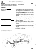
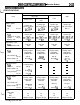
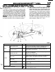
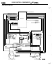
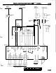
ABS ELECTRICAL CIRCUIT DIAGRAM
L
Ignition
switch IG2
0
L
10A
ABS-ECU
L
1
Dedicated
fuse
Hydraulic
unit
(HU)
ABS
motor
relay
18
1
Combination
meter
ii
::
u.
I
I
I-
I
26
Dedicated
fuse
Stop light
switch
p
valve power
supefvision
Sol&oid
FLw-
valve
{if
f
FR RL
Wheel speed sensor
28 30
M
RR
23 24
4-A
Data link
connector
1
2
3 4
5 6 7
8 9 10 11
12 13
14
15 16 17
18
19~20~21~22~23~24~25~26~27~28~29~30~31~32~33~34~35
ABS-ECU Connector Pin Configuration