
Manual

3-46
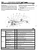
DRIVE-CONTROL COMPONENTS
-
ABS
<AWD>
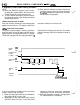
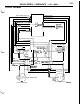
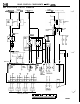
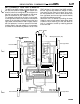
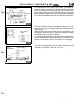
ABS ELECTRICAL CIRCUIT DIAGRAM
Ignition
switch
IG2
Ignition
Fusible link (2)
switch
IGl
,
Fusib i
-_
nk
(2)
Fusit
link (9)
0
L
IOA
Dedicated
1
[
fuse
Dedicated
fuse
Combination
meter
Stop light
switch
ABS
power
relay
$
Diode
1r
iydraulic
rnit (HU)
-
.-_
-
L
5
I:
I
7
ABS
valve
relay
n
r
26
7
k
Motor
valve
relay
relay
a
ib
Motor
’
7
power
SUPPlY
stop
light
-El
x
Y
F
I
1
Solenoid
valve
I
d
ABS-ECU
It-
I
A
r
I
ECU power
SUPPlY
-
-
L
2
,:
4
Resistor
L
29
*
Wheel speed sensor
1
2 3
4 5
6
7
8
9
10
11
12 13
14 15 16 17
18
19)20~21~22~23~24~25~26(27~26~29~30~31~32~33~34~35
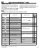
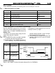
ABS-ECU Connector Pin Configuration