1A-1 ENGINE CONTENTS ENGINE <4G6> . . . . . . . . . . . . . . . . . . . . . . . . . . . . . . . . . . . . . . . . . . . . 11A ENGINE <6A1> . . . . . . . . . . . . . . . . . . . . . . . . . . . . . . . . . . . . . . . . . . . . 11B ENGINE <4D6> . . . . . . . . . . . . . . . . . . . . . . . . . . . . . . . . . . . . . . . . . . . .
11A-2 ENGINE <4G6> CONTENTS 11109000603 GENERAL INFORMATION . . . . . . . . . . . . . . . . . . 3 Lash Adjuster Check . . . . . . . . . . . . . . . . . . . . . . . . 11 SERVICE SPECIFICATIONS . . . . . . . . . . . . . . . . . 3 CRANKSHAFT PULLEY . . . . . . . . . . . . . . . . . . . 15 SEALANTS . . . . . . . . . . . . . . . . . . . . . . . . . . . . . . . . 4 CAMSHAFT AND CAMSHAFT OIL SEAL . . . 16 SPECIAL TOOLS . . . . . . . . . . . . . . . . . . . . . . . . . . . 4 OIL PAN . . . . . . . . . . .
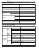
ENGINE <4G6> - General Information/Service Specifications GENERAL INFORMATION 11100010469 Items 4G63 Total displacement mL 1,997 Bore ´ Stroke mm 85.0 ´88.0 Compression ratio 10.
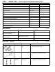
11A-4 ENGINE <4G6> - Service Specifications/Sealants/Special Tools Items Standard value Limit Idle speed r/min 750 ± 100 - CO contents % 0.5 or less - HC contents ppm 100 or less - Compression pressure (250 - 400 r/min) kPa 1,400 Min. 1,060 Compression pressure difference of all cylinder kPa - Max. 100 Intake manifold vacuum kPa - Min. 69 Cylinder head bolt shank length mm - 99.4 Auto-tensioner push rod movement mm Within 1 - Timing belt tension torque Nm (Reference value) 3.
ENGINE <4G6> - Special Tools Tool 11A-5 Number Name Use MD998713 Camshaft oil seal installer Press-in of the camshaft oil seal MD998443 Auto-lash adjuster holder Supporting of auto-lash adjuster MD998727 Oil pan remover Removal of oil pan MD998781 Flywheel stopper Securing the flywheel MD998776 Crankshaft rear oil seal installer Press-in of the crankshaft rear oil seal MB990938 Handle Press-in of the crankshaft rear oil seal MD998767 Tension pulley socket wrench Timing belt tension
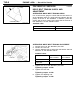
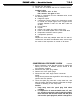
11A-6 ENGINE <4G6> - On-vehicle Service Alternator pulley Water pump pulley ON-VEHICLE SERVICE 11100090432 DRIVE BELT TENSION CHECK AND ADJUSTMENT Crankshaft pulley ALTERNATOR DRIVE BELT TENSION CHECK Use a belt tension gauge to check that the belt tension is at the standard value at a point half-way between the two pulleys as shown in the illustration. In addition, press this section with a force of 98 N and check that the amount of belt deflection is at the standard value.
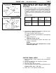
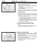
11A-7 ENGINE <4G6> - On-vehicle Service Oil pump pulley 98 N A B Crankshaft pulley Tensioner pulley POWER STEERING OIL PUMP AND AIR CONDITIONER COMPRESSOR DRIVE BELT TENSION CHECK AND ADJUSTMENT 11100130127 1. Use a belt tension gauge to check that the belt tension is at the standard value at a point half-way between the two pulleys (indicated by an arrow in the illustration).
11A-8 ENGINE <4G6> - On-vehicle Service 7. Check that basic ignition timing is within the standard value. Standard value: 5_ BTDC±2_ 8. If the basic ignition timing is outside the standard value, inspect the MPI system while referring to GROUP 13A - Troubleshooting. 9. Press the MUT-II clear key (Select a forced driving cancel mode) to release the Actuator test. Caution If the test is not cancelled, a forced driving will continue for 27 minutes. Driving under this condition may damage the engine. 10.
ENGINE <4G6> - On-vehicle Service 11A-9 5. Set the CO, HC tester. 6. Check the CO contents and the HC contents at idle. Standard value CO contents: 0.5% or less HC contents: 100 ppm or less 7. If there is a deviation from the standard value, check the following items: D Diagnosis output D Closed-loop control (When the closed-loop control is normal, the output signal of the oxygen sensor changes between 0 - 400 mV and 600 - 1,000 mV at idle.
11A-10 ENGINE <4G6> - On-vehicle Service 6. Set compression gauge to one of the spark plug holes. 7. Crank the engine with the throttle valve fully open and measure the compression pressure. Standard value (at engine speed of 250 - 400 r/min): 1,400 kPa Compression gauge Limit (at engine speed of 250 - 400 r/min): Min. 1,060 kPa 8. Measure the compression pressure for all the cylinders, and check that the pressure differences of the cylinders are below the limit. Limit: Max. 100 kPa 9.
ENGINE <4G6> - On-vehicle Service LASH ADJUSTER CHECK 11A-11 11100290344 If an abnormal noise (knocking) that seems to be coming from the lash adjuster is heard after starting the engine and does not stop, carry out the following check. NOTE (1) The abnormal noise which is caused by a problem with the lash adjusters is generated after the engine is started, and will vary according to the engine speed. However, this noise is not related to the actual engine load.
11A-12 ENGINE <4G6> - On-vehicle Service (3) Carry out lash adjuster simple check. (Refer to P.11A-13.) D If any of the rocker arms can be pushed down easily during the lash adjuster simple check, replace the corresponding lash adjusters. D If the lash adjuster simple check has been carried out but all lash adjusters are normal (if none of the rocker arms could be pushed down easily), check for some other cause of the problem.
ENGINE <4G6> - On-vehicle Service 11A-13 1. Stop the engine. 2. Remove the rocker cover. 3. Set the No.1 cylinder to the compression top dead centre position. 4. Check the rocker arms indicated by white arrows in the illustration by the procedures given below. Check whether the rocker arm moves downwards when the part of the rocker arm which touches the top of the lash adjuster is pushed.
11A-14 ENGINE <4G6> - On-vehicle Service 1. Check the engine oil and replenish or replace the oil if necessary. NOTE (1) If there is a only small amount of oil, air will be drawn in through the oil screen and will get into the oil passage. (2) If the amount of oil is greater than normal, then the oil will being mixed by the crankshaft and a large amount of air may get mixed into the oil.
ENGINE <4G6> - Crankshaft Pulley CRANKSHAFT PULLEY 11A-15 11200160303 REMOVAL AND INSTALLATION Pre-removal Operation D Under Cover Removal Post-installation Operation D Drive Belt Tension Adjustment (Refer to P.11A-6.) D Under Cover Installation 2 3 25 Nm 1 Removal steps 1. Drive belt (Power steering and A/C) 2. Drive belt (Alternator) 3.
11A-16 ENGINE <4G6> - Camshaft and Camshaft Oil Seal CAMSHAFT AND CAMSHAFT OIL SEAL 11200190418 REMOVAL AND INSTALLATION Pre-removal and Post-installation Operation D Air Cleaner Removal and Installation D Timing Belt Removal and Installation (Refer to P.11A-26.) D Relay Box Removal and Installation 10 Nm 5 1 2 (f 3 ± 1 mm) 4 3.
ENGINE <4G6> - Camshaft and Camshaft Oil Seal 11A-17 REMOVAL SERVICE POINTS AA" CAMSHAFT SPROCKET REMOVAL MB990767 MD998719 or MD998754 MD998443 AB" ROCKER ARM AND SHAFT ASSEMBLY REMOVAL Before removing the rocker arm and shaft assembly, install the special tools as shown in the illustration so that the lash adjusters will not fall out. INSTALLATION SERVICE POINTS "AA ROCKER ARM AND SHAFT ASSEMBLY INSTALLATION 1.
11A-18 ENGINE <4G6> - Camshaft and Camshaft Oil Seal "BA CAMSHAFT OIL SEAL INSTALLATION 1. Apply engine oil to the camshaft oil seal lip. 2. Use the special tool to press-fit the camshaft oil seal. MD998713 "CA CAMSHAFT SPROCKET INSTALLATION Use the special tool to stop the camshaft sprocket from turning in the same way as was done during removal, and then tighten the bolts to the specified torque.
11A-19 ENGINE <4G6> - Oil Pan OIL PAN 11200280207 REMOVAL AND INSTALLATION Pre-removal and Post-installation Operation D Engine Oil Draining and Supplying (Refer to GROUP 12 - On-vehicle Service.) D Oil Level Gauge Removal and Installation D Front Exhaust Pipe Removal and Installation (Refer to GROUP 15.) 5 f 4 ± 1 mm Groove Bolt hole 5 3 Sealant: MITSUBISHI GENUINE MD970389 or equivalent PART 4 7 Nm 9 Nm Removal steps 1. Drain plug "AA 2. Drain plug gasket 3.
11A-20 ENGINE <4G6> - Crankshaft Oil Seal CRANKSHAFT OIL SEAL 11200310135 REMOVAL AND INSTALLATION 127 - 137 Nm 7 9 8 11 12 127 - 137 Nm 6 2 8 4 10 1 5 Crankshaft (Engine oil: bolt washer surface) 3 Crankshaft (Engine oil: bolt washer surface) 12 5 Lip section 9 Lip section 10 Sealant: 3M Stud locking 4170 or equivalent Crankshaft front oil seal removal steps D Timing belt (Refer to P.11A-26.) D Crank angle sensor (Refer to GROUP 16.) 1.
ENGINE <4G6> - Crankshaft Oil Seal 11A-21 REMOVAL SERVICE POINTS AA" TRANSMISSION ASSEMBLY REMOVAL : Refer to GROUP 22. Flywheel Bolt Caution Do not remove the flywheel mounting bolt shown by the arrow. If this bolt Is removed, the flywheel will become out of balance and damaged. : Refer to GROUP 23. AB" PLATE /ADAPTER PLATE/FLYWHEEL /DRIVE PLATE REMOVAL Use the special tool to secure the flywheel or drive plate, and remove the bolts.
11A-22 ENGINE <4G6> - Cylinder Head Gasket CYLINDER HEAD GASKET 11200400542 REMOVAL AND INSTALLATION Pre-removal Operation D Fuel Discharge Prevention (Refer to GROUP 13A - On-vehicle Service.) D Engine Oil Draining (Refer to GROUP 12 On-vehicle Service.) D Thermostat Case Assembly Removal (Refer to GROUP 14 - Water Hose and Water Pipe.) Post-installation Operation D Thermostat Case Assembly Installation (Refer to GROUP 14 - Water Hose and Water Pipe.
11A-23 ENGINE <4G6> - Cylinder Head Gasket 10 Nm 15 14 78 Nm ® 0 Nm ® 20 Nm ® + 90_ ® + 90_ 16 3.4 Nm 27 12 (Engine oil) 26 17 19 28 13 29 22 49 Nm 18 20 21 24 24 Nm 44 Nm 25 34 Nm 23 31 Nm 12. 13. 14. 15. 16. 17. Radiator upper hose connection PCV hose Ignition coil connector Ignition coil assembly Breather hose Engine coolant temperature sensor connector 18. Engine coolant temperature gauge unit connector 19. Camshaft position sensor 20. Water hose connection AA" 21.
11A-24 ENGINE <4G6> - Cylinder Head Gasket REMOVAL SERVICE POINTS AA" POWER STEERING OIL PUMP AND BRACKET ASSEMBLY REMOVAL Remove the power steering oil pump and bracket assembly from the engine with the hose attached. NOTE Place the removed power steering oil pump in a place where it will not be a hindrance when removing and installing the cylinder head assembly, and tie it with a cord.
11A-25 ENGINE <4G6> - Cylinder Head Gasket Intake side 8 6 10 4. Tighten the bolts by the following procedure. Front of engine 4 1 2 3 5 Step Operation Remarks 1 Tighten to 78 Nm. Carry out in the order shown in the illustration. 2 Fully loosen. Carry out in the reverse order of that shown in the illustration. 3 Tighten to 20 Nm. Carry out in the order shown in the illustration. 4 Tighten 90_ of a turn. In the order shown in the illustration.
11A-26 ENGINE <4G6> - Timing Belt TIMING BELT 11200430473 REMOVAL AND INSTALLATION Pre-removal and Post-installation Operation D Crankshaft Pulley Removal and Installation (Refer to P.11A-15.) D Engine Mount Bracket Removal and Installation (Refer to GROUP 32 - Engine Mounting.) 3 1 10 - 12 Nm 48 Nm 5 4 24 Nm 9 Nm 2 Removal steps 1. Timing belt upper cover 2. Timing belt lower cover "CA D Timing belt tension adjustment AA" "BA 3. Timing belt 4. Tension pulley "AA 5.
ENGINE <4G6> - Timing Belt Timing mark (Top of cylinder head) Timing mark Camshaft sprocket Timing mark Timing mark Timing mark Oil pump sprocket Crankshaft sprocket 11A-27 REMOVAL SERVICE POINT AA" TIMING BELT REMOVAL 1. Turn the crankshaft clockwise (right turn) to align each timing mark and to set the No. 1 cylinder at compression top dead centre. Caution The crankshaft should always be turned only clockwise. 2. Loosen the tension pulley centre bolt. 3.
11A-28 ENGINE <4G6> - Timing Belt 4. Once the holes are aligned, insert the set pin. Set pin NOTE When replacing the auto tensioner with a new part, the pin will be in the auto tensioner. 5. Install the auto tensioner to the engine. Timing mark (Top of cylinder head) Timing mark Camshaft sprocket Timing mark Timing mark Timing mark Oil pump sprocket Crankshaft sprocket Plug "BA TIMING BELT INSTALLATION 1. Align the timing marks on the camshaft sprocket, crankshaft sprocket and oil pump sprocket.
ENGINE <4G6> - Timing Belt 50 Nm MD998767 Tension direction 11A-29 "CA TIMING BELT TENSION ADJUSTMENT 1. After turning the crankshaft 1/4 of a revolution in the anticlockwise direction, turn it in the clockwise direction until the timing marks are aligned. 2. Loosen the tension pulley fixing bolt, and then use the special tool and a torque wrench to tighten the fixing bolt to the specified torque while applying tension to the timing belt. Standard value: 3.
11A-30 ENGINE <4G6> - Timing Belt B TIMING BELT B 11200460106 REMOVAL AND INSTALLATION 5 1 19 Nm 4 3 2 108 - 127 Nm Removal steps 1. Timing belt (Refer to P.11A-26.) AA" "CA 2. Crankshaft sprocket "BA 3. Flange Crankshaft sprocket MD998719 or MD998754 4. Timing belt B tensioner AB" "AA 5.
ENGINE <4G6> - Timing Belt B Counterbalance shaft sprocket Belt tension side Timing marks Timing marks Crankshaft sprocket B 11A-31 INSTALLATION SERVICE POINTS "AA TIMING BELT B INSTALLATION, ADJUSTMENT 1. Install timing belt “B” by the following procedure. (1) Ensure that crankshaft sprocket “B” timing mark and the counterbalance shaft sprocket timing mark are aligned. (2) Fit timing belt “B” over crankshaft sprocket “B” and the counterbalance shaft sprocket. Ensure that there is no slack in the belt.
11A-32 Crankshaft sprocket ENGINE <4G6> - Timing Belt B MD998719 or MD998754 MB990767 "CA CRANKSHAFT SPROCKET INSTALLATION NOTE Apply the minimum amount of engine oil to the bearing surface and thread of the crankshaft bolt.
11A-33 ENGINE <4G6> - Engine Assembly ENGINE ASSEMBLY 11200090015 REMOVAL AND INSTALLATION Pre-removal Operation D Fuel Discharge Prevention (Refer to GROUP 13A - On-vehicle Service.) D Engine Coolant Draining D Thermostat Case Assembly Removal (Refer to GROUP 14 - Water Hose and Water Pipe.) D Front Exhaust Pipe Removal (Refer to GROUP 15.) D Hood Removal (Refer to GROUP 42.) D Under Cover Removal D Radiator Assembly Removal (Refer to GROUP 14.
11A-34 ENGINE <4G6> - Engine Assembly 20 15 26 23 22 49 Nm 21 19 16 17 18 14 13 57 Nm* 24 25 25 98 Nm AA" AB" 13. Drive belt (Alternator) 14. Drive belt (Power steering and A/C) 15. Power steering oil pump and bracket assembly 16. A/C compressor 17. Alternator connector 18. Oil pressure switch connector 19. Heater hose connection 20. Engine coolant temperature gauge unit connector 21. Engine coolant temperature sensor connector 22. 23. AC" D AD" "CA 24. "BA 25. AE" "AA 26.
ENGINE <4G6> - Engine Assembly 11A-35 REMOVAL SERVICE POINTS AA" POWER STEERING OIL PUMP AND BRACKET ASSEMBLY REMOVAL Remove the power steering oil pump and bracket assembly from the engine with the hose attached. NOTE Place the removed power steering oil pump in a place where it will not be a hindrance when removing and installing the engine assembly, and tie it with a cord.
11A-36 ENGINE <4G6> - Engine Assembly INSTALLATION SERVICE POINTS "AA ENGINE ASSEMBLY INSTALLATION Install the engine assembly, checking that the cables, hoses, and harness connectors are not clamped. Engine side Dynamic damper Arrow "BA ENGINE MOUNT STOPPER INSTALLATION Clamp the engine mount stopper so that the arrow points in the direction as shown in the diagram. Engine mount stopper Engine mount bracket "CA ENGINE MOUNT BRACKET INSTALLATION 1.
11B-1 ENGINE <6A1> CONTENTS 11109000610 GENERAL INFORMATION . . . . . . . . . . . . . . . . . . 2 CRANKSHAFT PULLEY . . . . . . . . . . . . . . . . . . . 14 SERVICE SPECIFICATIONS . . . . . . . . . . . . . . . . . 2 CAMSHAFT AND CAMSHAFT OIL SEAL . . . 15 SEALANTS . . . . . . . . . . . . . . . . . . . . . . . . . . . . . . . . 3 OIL PAN . . . . . . . . . . . . . . . . . . . . . . . . . . . . . . . . . . 18 SPECIAL TOOLS . . . . . . . . . . . . . . . . . . . . . . . . . . . 3 CRANKSHAFT OIL SEAL .
11B-2 ENGINE <6A1> - General Information/Service Specifications GENERAL INFORMATION 11100010452 Items 6A13 Total displacement mL 2,498 Bore ´ Stroke mm 81.0 ´ 80.8 Compression ratio 9.
ENGINE <6A1> - Service Specifications/Sealants/Special Tools Items Standard value Limit Idle speed r/min 650 ± 100 - CO contents % 0.2 or less - HC contents ppm 100 or less - Compression pressure (250 - 400 r/min) kPa 1177 Min. 875 Compression pressure difference of all cylinder kPa - Max. 98 Intake manifold vacuum kPa - Min. 60 Cylinder head bolt shank length mm - 96.
11B-4 Tool ENGINE <6A1> - Special Tools Number Name Use MD998443 Auto-lash adjuster holder Supporting of auto-lash adjuster MD998713 Camshaft oil seal installer Press-in of the camshaft oil seal MD998776 Crankshaft rear oil seal installer Press-in of the crankshaft rear oil seal MB990938 Handle Press-in of the crankshaft rear oil seal MD998767 Tension pulley socket wrench Timing belt tension adjustment MD998717 Crankshaft front oil seal installer Press-in of the crankshaft front oil sea
11B-5 ENGINE <6A1> - Special Tools/On-vehicle Service Tool Alternator pulley Number Name Use MB991453 Engine hanger assembly Supporting the engine assembly during removal and installation of the transmission Tension pulley ON-VEHICLE SERVICE 11100090425 DRIVE BELT TENSION CHECK AND ADJUSTMENT ALTERNATOR DRIVE BELT TENSION CHECK Use a belt tension gauge to check that the belt tension is at the standard value at a point half-way between the two pulleys as shown in the illustration.
11B-6 ENGINE <6A1> - On-vehicle Service Power steering oil pump pulley A A/C compressor pulley Crankshaft pulley B POWER STEERING OIL PUMP AND AIR CONDITIONER COMPRESSOR DRIVE BELT TENSION CHECK AND ADJUSTMENT 11100130134 1. Use a belt tension gauge to check that the belt tension is at the standard value at a point half-way between the two pulleys (indicated by an arrow in the illustration).
ENGINE <6A1> - On-vehicle Service 11B-7 9. Press the MUT-II clear key (Select a forced driving cancel mode) to release the Actuator test. Caution If the test is not cancelled, a forced driving will continue for 27 minutes. Driving under this condition may damage the engine. 10. Check that ignition timing is at the standard value. Standard value: approx. 7_BTDC NOTE 1. Ignition timing is variable within about ± 7_, even under normal operating. 2.
11B-8 ENGINE <6A1> - On-vehicle Service 5. Set the CO, HC tester. 6. Check the CO contents and the HC contents at idle. Standard value CO contents: 0.2% or less HC contents: 100 ppm or less 7. If there is a deviation from the standard value, check the following items: D Diagnosis output D Closed-loop control (When the closed-loop control is normal, the output signal of the oxygen sensor changes between 0 - 400 mV and 600 - 1,000 mV at idle.
ENGINE <6A1> - On-vehicle Service Compression gauge 11B-9 6. Set compression gauge to one of the spark plug holes. 7. Crank the engine with the throttle valve fully open and measure the compression pressure. Standard value (at engine speed of 250 - 400 r/min): 1,177 kPa Limit (at engine speed of 250 - 400 r/min): Min. 875 kPa 8. Measure the compression pressure for all the cylinders, and check that the pressure differences of the cylinders are below the limit. Limit: Max. 98 kPa 9.
11B-10 ENGINE <6A1> - On-vehicle Service LASH ADJUSTER CHECK 11100290337 If an abnormal noise (knocking) that seems to be coming from the lash adjuster is heard after starting the engine and does not stop, carry out the following check. NOTE (1) The abnormal noise which is caused by a problem with the lash adjusters is generated after the engine is started, and will vary according to the engine speed. However, this noise is not related to the actual engine load.
ENGINE <6A1> - On-vehicle Service 11B-11 (3) Carry out lash adjuster simple check. (Refer to P.11B-12.) D If any of the rocker arms can be pushed down easily during the lash adjuster simple check, replace the corresponding lash adjusters. D If the lash adjuster simple check has been carried out but all lash adjusters are normal (if none of the rocker arms could be pushed down easily), check for some other cause of the problem.
11B-12 Timing belt side ENGINE <6A1> - On-vehicle Service 1. Stop the engine. 2. Remove the rocker cover. 3. Set the No.1 cylinder to the compression top dead centre position. 4. Check the rocker arms indicated by white arrows in the illustration by the procedures given below. Check whether the rocker arm moves downwards when the part of the rocker arm which touches the top of the lash adjuster is pushed.
ENGINE <6A1> - On-vehicle Service 11B-13 1. Check the engine oil and replenish or replace the oil if necessary. NOTE (1) If there is a only small amount of oil, air will be drawn in through the oil screen and will get into the oil passage. (2) If the amount of oil is greater than normal, then the oil will being mixed by the crankshaft and a large amount of air may get mixed into the oil.
11B-14 ENGINE <6A1> - Crankshaft Pulley CRANKSHAFT PULLEY 11200160310 REMOVAL AND INSTALLATION Pre-removal Operation D Under Cover Removal Post-installation Operation D Drive Belt Tension Adjustment (Refer to P.11B-5.) D Under Cover Installation (Engine oil) 3 1 4 5 177 - 186 Nm 2 Removal steps 1. Drive belt (Power steering oil pump, or A/C compressor and power steering oil pump) 2. Drive belt (Alternator) AA" "AA 3. Crankshaft bolt 4. Washer 5.
11B-15 ENGINE <6A1> - Camshaft and Camshaft Oil Seal CAMSHAFT AND CAMSHAFT OIL SEAL 11200220124 REMOVAL AND INSTALLATION Pre-removal and Post-installation Operation D Engine Coolant Draining and Refilling (Refer to GROUP 14 - On-vehicle Service.) D Air Intake Hose Assembly Removal and Installation D D Timing Belt Removal and Installation (Refer to P.11B-26.) Drive Belt Tension Adjustment (Refer to P.11B-5.) Apply engine oil to all sliding parts when installing. 6 3 4 1 3.
11B-16 ENGINE <6A1> - Camshaft and Camshaft Oil Seal Pre-removal and Post-installation Operation D Air Intake Plenum Removal and Installation (Refer to GROUP 15.) D Timing Belt Removal and Installation (Refer to P.11B-26.) D D Distributor Removal and Installation (Refer to GROUP 16.) Drive Belt Tension Adjustment (Refer to P.11B-5.) Apply engine oil to all sliding parts when installing. 6 1 7 3.4 Nm 2 28 - 34 Nm 12 8 9 13 88 Nm Removal steps 1. Breather hose connection 2.
ENGINE <6A1> - Camshaft and Camshaft Oil Seal 11B-17 AB" CAMSHAFT SPROCKET REMOVAL MB990767 MD998715 AC" ROCKER ARM AND SHAFT ASSEMBLY REMOVAL 1. Install the special tools as shown in the illustration so that the lash adjusters will not fall out. MD998443 2. Loosen the rocker arm and shaft assembly mounting bolt, and then remove the rocker arm and shaft assembly with the bolt still attached. Caution Never disassemble the rocker arm assembly.
11B-18 ENGINE <6A1> - Camshaft and Camshaft Oil Seal "CA CAMSHAFT SPROCKET INSTALLATION Use the special tool to stop the camshaft sprocket from turning in the same way as was done during removal, and then tighten the bolts to the specified torque. Tightening torque: 88 Nm "DA RADIATOR LOWER HOSE/RADIATOR UPPER HOSE CONNECTION 1. Insert each hose as far as the projection of the water inlet fitting. 2. Align the mating marks on the radiator hose and hose clamp, and then connect the radiator hose.
11B-19 ENGINE <6A1> - Oil Pan OIL PAN 11200280214 REMOVAL AND INSTALLATION Pre-removal and Post-installation Operation D Engine Oil Draining and Supplying (Refer to GROUP 12 - On-vehicle Service.) D Oil Level Gauge Removal and Installation D Front Exhaust Pipe Removal and Installation (Refer to GROUP 15.
11B-20 MD998727 ENGINE <6A1> - Oil Pan MD998727 REMOVAL SERVICE POINT AA" LOWER OIL PAN/UPPER OIL PAN REMOVAL After removing the oil pan mounting bolts, remove the oil pan with the special tool and a brass bar. Caution Perform this slowly to avoid deformation of the oil pan flange. INSTALLATION SERVICE POINT Oil pan side Drain plug gasket "AA DRAIN PLUG GASKET INSTALLATION Install the drain plug gasket in the direction so that it faces as shown in the illustration.
11B-21 ENGINE <6A1> - Crankshaft Oil Seal CRANKSHAFT OIL SEAL 11200310142 REMOVAL AND INSTALLATION Crankshaft (Engine oil: bolt washer surface) 5 4 8 3 1 2 Crankshaft (Engine oil: bolt washer surface) 10 7 9 8 6 Sealant: 3M Stud Locking 4170 or equivalent 5 11 Lip section 11 93 - 103 Nm 10 Lip section 7 Engine oil Crankshaft front oil seal removal steps D Timing belt (Refer to P.11B-26.) D Crank angle sensor (Refer to GROUP 16.) 1. Crankshaft sprocket 2.
11B-22 ENGINE <6A1> - Crankshaft Oil Seal REMOVAL SERVICE POINTS AA" TRANSMISSION ASSEMBLY REMOVAL : Refer to GROUP 22. Flywheel Bolt Caution Do not remove the flywheel mounting bolt shown by the arrow. If this bolt Is removed, the flywheel will become out of balance and damaged. : Refer to GROUP 23. AB" PLATE /ADAPTER PLATE/FLYWHEEL /DRIVE PLATE REMOVAL Use the special tool to secure the flywheel or drive plate, and remove the bolts.
ENGINE <6A1> - Crankshaft Oil Seal Crankshaft MD998717 MD998717 Oil seal 11B-23 "CA CRANKSHAFT FRONT OIL SEAL INSTALLATION 1. Apply a small amount of engine oil to the entire circumference of the oil seal lip. 2. Tap the oil seal unit it is flush with the oil seal case.
11B-24 ENGINE <6A1> - Cylinder Head Gasket CYLINDER HEAD GASKET 11200400559 REMOVAL AND INSTALLATION Pre-removal and Post-installation Operation D Engine Coolant Draining and Refilling (Refer to GROUP 14 - On-vehicle Service.) D Air Intake Hose Assembly Removal and Installation D Radiator Assembly Removal and Installation (Refer to GROUP 14 - Radiator.) D Air Intake Plenum and Intake Manifold Removal and Installation (Refer to GROUP 15 - Air Intake Plenum.
ENGINE <6A1> - Cylinder Head Gasket REMOVAL SERVICE POINT Exhaust side Intake side 11B-25 Front of engine AA" CYLINDER HEAD BOLT REMOVAL Loosen the bolts in 2 or 3 steps in order of the numbers shown in the illustration, and remove the cylinder head assembly. Exhaust side INSTALLATION SERVICE POINTS Identification mark "AA CYLINDER HEAD GASKET INSTALLATION 1. Wipe off all oil and grease from the gasket mounting surface. 2.
11B-26 ENGINE <6A1> - Timing Belt TIMING BELT 11200430480 REMOVAL AND INSTALLATION Pre-removal and Post-installation Operation D Under Cover Removal and Installation D Crankshaft Pulley Removal and Installation D Alternator Removal and Installation (Refer to GROUP 16.) D Drive Belt Tension Adjustment (Refer to P.11B-5.) 3 Nm 1 44 Nm 9 12 Nm 10 3 7 8 10 - 12 Nm 6 4 24 Nm 10 - 12 Nm 5 35 Nm 24 Nm 22 Nm 11 2 14 13 10 - 12 Nm 12 Removal steps 1. Engine cover 2. Engine mount stay 3.
ENGINE <6A1> - Timing Belt 11B-27 REMOVAL SERVICE POINT AA" TIMING BELT REMOVAL 1. Align each of the timing marks. Tensioner pulley Timing marks 2. Loosen the centre bolt of the tension pulley and remove the timing belt. Caution (1) If the timing belt is to be reused, use chalk to mark it with an arrow on its flat side indicating the turning direction.
11B-28 Rocker cover ENGINE <6A1> - Timing Belt Rocker cover Camshaft sprocket Camshaft sprocket Timing marks "BA TIMING BELT INSTALLATION 1. Check that the timing marks of the both camshaft sprockets and the crankshaft sprocket are aligned. NOTE In this condition, the No.1 cylinder will be in the compression top dead centre position. Crankshaft sprocket Tension side A Rear bank side camshaft sprocket Tension side B Tension side C Tension side D Pin holes 2.
ENGINE <6A1> - Timing Belt MD998767 Tension direction Tensioner pulley 48 Nm 11B-29 "CA TIMING BELT TENSION ADJUSTMENT 1. After turning the crankshaft 1/4 of a revolution in the anticlockwise direction, turn it in the clockwise direction until the timing marks are aligned. 2. Loosen the tensioner pulley fixing bolt, and then use the special tool and a torque wrench to tighten the fixing bolt to the specified torque while applying tension to the timing belt.
11B-30 ENGINE <6A1> - Engine Assembly ENGINE ASSEMBLY 11200100558 REMOVAL AND INSTALLATION Pre-removal Operation D Fuel Discharge Prevention (Refer to GROUP 13A - On-vehicle Service.) D Under Cover Removal D Hood Removal (Refer to GROUP 42.) D Air Cleaner Removal D Radiator Removal (Refer to GROUP 14.) D Front Exhaust Pipe Removal (Refer to GROUP 15.) D Engine Cover Removal D Battery Removal D Engine Coolant Draining Post-installation Operation D Front Exhaust Pipe Installation (Refer to GROUP 15.
11B-31 ENGINE <6A1> - Engine Assembly 30 12 Nm 28 27 27 12 Nm 27 39 Nm 25 26 34 29 35 Nm 31 67 Nm 32 33 57 Nm 33 98 - 118 Nm* AA" AB" AC" 25. Drive belt (Alternator) 26. Drive belt (Power steering and A/C) 27. Clamp bolt (Power steering hose and pipe) 28. Power steering oil pump assembly 29. A/C compressor 30. Heater hose connection D Transmission assembly 31. Engine mount stay AD" "CA 32. Engine mount bracket "BA 33. Engine mount stopper AE" "AA 34.
11B-32 ENGINE <6A1> - Engine Assembly REMOVAL SERVICE POINTS AA" POWER STEERING OIL PUMP AND BRACKET ASSEMBLY REMOVAL Remove the power steering oil pump and bracket assembly from the engine with the hose attached. NOTE Place the removed power steering oil pump in a place where it will not be a hindrance when removing and installing the engine assembly, and tie it with a cord.
ENGINE <6A1> - Engine Assembly 11B-33 INSTALLATION SERVICE POINTS "AA ENGINE ASSEMBLY INSTALLATION Install the engine assembly, checking that the cables, hoses, and harness connectors are not clamped. Engine side Dynamic damper "BA ENGINE MOUNT STOPPER INSTALLATION Clamp the engine mount stopper so that the arrow points in the direction as shown in the diagram. Arrow Engine mount stopper Engine mount bracket "CA ENGINE MOUNT BRACKET INSTALLATION 1.
NOTES
11C-1 ENGINE <4D6> CONTENTS 11109000627 GENERAL INFORMATION . . . . . . . . . . . . . . . . . . 2 CRANKSHAFT PULLEY . . . . . . . . . . . . . . . . . . . 15 SERVICE SPECIFICATIONS . . . . . . . . . . . . . . . . . 2 CAMSHAFT AND CAMSHAFT OIL SEAL . . . 16 SEALANTS . . . . . . . . . . . . . . . . . . . . . . . . . . . . . . . . 3 OIL PAN . . . . . . . . . . . . . . . . . . . . . . . . . . . . . . . . . . 18 SPECIAL TOOLS . . . . . . . . . . . . . . . . . . . . . . . . . . . 4 CRANKSHAFT OIL SEAL .
11C-2 ENGINE <4D6> - General Information/Service Specifications GENERAL INFORMATION 11100010476 Items 4D68 Total displacement mL 1,998 Bore ´ Stroke mm 82.7 ´ 93.0 Compression ratio 22.
11C-3 ENGINE <4D6> - Service Specifications/Sealants Items Standard value Limit When checked 294 - 490 - When a used belt is installed 343 - 441 - When a new belt is installed 490 - 686 - When checked 12.6 - 16.3 - When a used belt is installed 13.4 - 15.3 - When a new belt is installed 10.0 - 12.6 - When checked 392 - 588 - When a used belt is installed 441 - 539 - When a new belt is installed 637 - 833 - When checked 9.2 - 12.0 - When a used belt is installed 9.8 - 11.
11C-4 ENGINE <4D6> - Special Tools SPECIAL TOOLS Tool 11100060471 Number Name Use MB991502 MUT-II sub assembly Idle speed check MB998720 Prestroke measuring adapter Adjustment of the injection timing MB990767 End yoke holder Holding the camshaft sprocket MD998719 Crankshaft pulley holder pin MD998754 Crankshaft pulley holder pin MD998364 Camshaft oil seal installer Installing the camshaft oil seal MD998727 Oil pan remover Removal of oil pan MD998776 Crankshaft rear oil seal instal
ENGINE <4D6> - Special Tools Tool 11C-5 Number Name Use MD998382 Crankshaft front oil seal installer Installing the crankshaft front oil seal MD998383 Crankshaft front oil seal guide MD998781 Flywheel stopper Securing the flywheel or drive plate GENERAL SERVICE TOOL MZ203827 Engine lifter Supporting the engine assembly during removal and installation of the transmission MB991453 Engine hanger assembly
11C-6 ENGINE <4D6> - On-vehicle Service ON-VEHICLE SERVICE 11100090449 DRIVE BELT TENSION CHECK AND ADJUSTMENT Alternator pulley A Water pump pulley ALTERNATOR DRIVE BELT TENSION CHECK Use a belt tension gauge to check that the belt tension is at the standard value at a point half-way between the two pulleys as shown in the illustration. In addition, press this section with a force of 98 N and check that the amount of belt deflection is at the standard value.
11C-7 ENGINE <4D6> - On-vehicle Service Power steering oil pump pulley POWER STEERING OIL PUMP DRIVE BELT TENSION CHECK AND ADJUSTMENT 11100110183 1. Check the tension by pulling or pushing at the centre of the belt between pulleys with a force of 98 N as shown in the figure. Measure drive belt deflection amount.
11C-8 ENGINE <4D6> - On-vehicle Service A A/C compressor pulley COMPRESSOR DRIVE BELT TENSION CHECK AND ADJUSTMENT 11100100203 1. Check the tension by pulling or pushing at the centre of the belt between pulleys with a force of 98 N as shown in the figure. Measure drive belt deflection amount. Standard value: Crankshaft pulley Items When checked When a used belt is installed When a new belt is installed Tension N 392 - 588 441 - 539 637 - 833 Deflection (Reference value) mm 9.2 - 12.0 9.
11C-9 ENGINE <4D6> - On-vehicle Service 6. Measure the valve clearance in the places indicated by arrows in the illustration. Arrow A: When the No.1 cylinder is at compression top dead centre Arrow B: When the No.4 cylinder is at compression top dead centre Timing belt side Standard value: A B Adjusting screw Pad Flat-tipped screwdriver Pad Thickness gauge When warm When cold (NOTE) Intake 0.35 mm 0.25 mm Exhaust 0.45 mm 0.
11C-10 ENGINE <4D6> - On-vehicle Service 8. Tighten the lock nut while holding the adjusting screw with a screwdriver so that it doesn’t turn. 9. Turn the crankshaft one full revolution to align the crankshaft pulley timing mark. 10. Adjust the remaining valves by the same procedure as in steps 7. - 9. above. 11. Install the glow plugs and the glow plug plate. 12. Install the rocker cover. 13. Install the timing belt upper cover. INJECTION TIMING CHECK AND ADJUSTMENT 11100180054 1.
ENGINE <4D6> - On-vehicle Service Set to 0 7. Turn the crankshaft clockwise to move the No.1 cylinder approximately 30_ before compression top dead centre. 8. Set the needle of the dial gauge to 0. 9. Check that the needle doesn’t move even if the crankshaft is turned slightly (2 - 3_) in both clockwise and anti-clockwise direction. NOTE If the needle moves, the notch is not positioned properly, so once again move the No.1 cylinder approximately 30_ before compression top dead centre. Approx.
11C-12 ENGINE <4D6> - On-vehicle Service IDLE SPEED CHECK 11100350073 NOTE Check that the injection timing is normal, and then perform this check. 1. Before inspection, set the vehicle to the pre-inspection condition. 2. Connect the MUT-II to the diagnosis connector. 3. Start the engine and check that the idle speed is at the standard value. Standard value: 800 ± 30 r/min 4. If the idle speed is not at the standard value, refer to GROUP 13E - Troubleshooting. COMPRESSION PRESSURE CHECK 11100260505 1.
ENGINE <4D6> - On-vehicle Service Compression gauge 11C-13 5. Set compression gauge to one of the glow plug holes. 6. Crank the engine and measure the compression pressure. Standard value: 3,500 kPa (at engine speed of 280 r/min) Limit: Min. 2,560 kPa (at engine speed of 280 r/min) Adapter 7. Measure the compression pressure for all cylinders, and check that the pressure differences of the cylinders are below the limit. Limit: Max. 300 kPa 8.
11C-14 ENGINE <4D6> - On-vehicle Service 5. Turn the crankshaft anti-clockwise by 1/2 the width of a camshaft sprocket tooth in order to take up the slack in the idler pulley belt (the side where the belt is slack). Timing mark 1/2 the width of a tooth Timing mark 6. Loosen the timing belt tensioner mounting bolt by 1/4 - 1/3 a turn, and use the force of the tensioner spring to apply tension to the belt. 7. Turn the crankshaft anti-clockwise again by the width of three camshaft sprocket teeth.
ENGINE <4D6> - Crankshaft Pulley CRANKSHAFT PULLEY 11C-15 11200160327 REMOVAL AND INSTALLATION Pre-removal Operation D Under Cover Removal Post-installation Operation D Drive Belt Tension Adjustment (Refer to P.11C-6.) D Under Cover Installation 4 3 1 25 Nm 2 Removal steps 1. Drive belt (Power steering) 2. Drive belt (A/C) 3. Drive belt (Alternator) 4.
11C-16 ENGINE <4D6> - Camshaft and Camshaft Oil Seal CAMSHAFT AND CAMSHAFT OIL SEAL 11200190425 REMOVAL AND INSTALLATION Pre-removal and Post-installation Operation D Timing Belt Removal and Installation (Refer to P.11C-26.) D Air Pipe A Removal and Installation D Vacuum Pump Removal and Installation (Refer to GROUP 14.) 6 Nm 1 Lip section 5 3 2 19 - 21 Nm 27 - 31 Nm 8 27 - 31 Nm 7 19 - 21 Nm 6 7 Cam section and journal section 7 19 - 21 Nm 5 4 Engine oil 8 88 Nm Removal steps 1.
ENGINE <4D6> - Camshaft and Camshaft Oil Seal 11C-17 REMOVAL SERVICE POINT MB990767 AA" CAMSHAFT SPROCKET REMOVAL MD998719 or MD998754 INSTALLATION SERVICE POINTS Camshaft sproket side "AA CAMSHAFT BEARING CAP INSTALLATION The cap numbers are embossed on the top surface of the bearing caps, so install in the order of the numbers. However, no numbers are embossed on bearing caps 1 and 5. Cap No. "BA ROCKER ARM AND SHAFT ASSEMBLY INSTALLATION 1.
11C-18 ENGINE <4D6> - Oil Pan OIL PAN 11200280221 REMOVAL AND INSTALLATION Pre-removal and Post-installation Operation D Under Cover Removal and Installation D Front Exhaust Pipe Removal and Installation (Refer to GROUP 15.) D D Engine Oil Level Gauge Removal and Insertion Engine Oil Draining and Refilling (Refer to GROUP 12 - On-vehicle Service.
ENGINE <4D6> - Oil Pan MD998727 MD998727 11C-19 REMOVAL SERVICE POINT AA" OIL PAN REMOVAL After removing the oil pan mounting bolts, remove the oil pan with the special tool and a brass bar. Caution Perform this slowly to avoid deformation of the oil pan flange. INSTALLATION SERVICE POINT Oil pan side Drain plug gasket "AA DRAIN PLUG GASKET INSTALLATION Install the drain plug gasket in the direction so that it faces as shown in the illustration.
11C-20 ENGINE <4D6> - Crankshaft Oil Seal CRANKSHAFT OIL SEAL 11200310159 REMOVAL AND INSTALLATION 9 127 - 137 Nm 10 6 11 7 5 4 3 127 - 137 Nm 2 1 6 8 10 (Engine oil) 108 - 127 Nm Crankshaft (Engine oil: bolt washer surface) 5 11 Lip section Crankshaft (Engine oil: bolt washer surface) Lip section 9 Engine oil Crankshaft front oil seal removal steps D Timing belt (Refer to P.11C-26.) D Crank angle sensor (Refer to GROUP 16.) 1. Crankshaft sprocket 2. Flange 3.
ENGINE <4D6> - Crankshaft Oil Seal 11C-21 REMOVAL SERVICE POINT AA" TRANSMISSION ASSEMBLY REMOVAL : Refer to GROUP 22. Flywheel Bolt Caution Do not remove the flywheel mounting bolt shown by the arrow. If this bolt Is removed, the flywheel will become out of balance and damaged. : Refer to GROUP 23. AB" ADAPTER PLATE/FLYWHEEL /DRIVE PLATE REMOVAL Use the special tool to secure the flywheel or drive plate, and remove the bolts.
11C-22 ENGINE <4D6> - Crankshaft Oil Seal Crankshaft MD998382 Oil seal MD998383 Front lower case "CA CRANKSHAFT FRONT OIL SEAL INSTALLATION 1. Apply a small amount of engine oil to the entire circumference of the oil seal lip. 2. Tap the oil seal unit it is flush with the oil seal case.
11C-23 ENGINE <4D6> - Cylinder Head Gasket CYLINDER HEAD GASKET 11200400566 REMOVAL AND INSTALLATION Pre-removal and Post-installation Operation D Engine Coolant Draining and Refilling (Refer to GROUP 14 - On-vehicle Service.) D Air Pipe A Removal and Installation (Refer to GROUP 15 - Intercooler.) D Vacuum Pump Removal and Installation (Refer to GROUP 14.) D D Timing Belt Removal and Installation (Refer to P.11C-26.
11C-24 AA" FUEL INJECTION PIPE REMOVAL When loosening nuts at injection pipe ends, hold the nut at other side (delivery holder nut for pump side, nozzle holder nut at nozzle side) with wrench. Caution After disconnecting the injection pipe, plug the opening so that no foreign particles get inside the pump or into the injection nozzle.
11C-25 ENGINE <4D6> - Cylinder Head Gasket Intake side 8 6 10 4. Tighten the bolts by the following procedure. Front of engine 4 1 2 3 5 Step Operation Remarks 1 Tighten to 88 Nm. Carry out in the order shown in the illustration. 2 Fully loosen. Carry out in the reverse order of that shown in the illustration. 3 Tighten to 39 Nm. Carry out in the order shown in the illustration. 4 Tighten 90_ of a turn. In the order shown in the illustration.
11C-26 ENGINE <4D6> - Timing Belt TIMING BELT 11200430497 REMOVAL AND INSTALLATION Pre-removal and Post-installation Operation D Crankshaft Pulley Removal and Installation (Refer to P.11C-15.) D Engine Mount Bracket Removal and Installation (Refer to GROUP 32.) 3 10 - 12 Nm 7 9 Nm 10 - 12 Nm 1 19 Nm 25 Nm 10 - 12 Nm 4 10 - 12 Nm 6 2 5 9 Nm 23 Nm AA" 10 - 12 Nm Removal steps 1. Water pump pulley 2. A/C tension pulley assembly 3. Timing belt front upper cover 4.
ENGINE <4D6> - Timing Belt 11C-27 REMOVAL SERVICE POINTS AA" TIMING BELT FRONT UPPER COVER INSTALLATION Attach protective tape to the engine mount bracket, and then remove the timing belt front upper cover. Protective tape Timing marks AB" TIMING BELT REMOVAL 1. Align the timing marks. 2. Loosen the installation bolt of the timing belt tensioner. 3. Move the timing belt tensioner downward and loosely tighten the bolt so that the tensioner doesn’t return; then remove the timing belt.
11C-28 ENGINE <4D6> - Timing Belt INSTALLATION SERVICE POINTS Timing marks Injection pump sprocket Camshaft sprocket Timing mark Crankshaft sprocket "AA TIMING BELT INSTALLATION 1. Ensure that the timing marks of the camshaft sprocket, the injection pump sprocket, the crankshaft sprocket, and the oil pump sprocket are all aligned. Timing mark Oil pump sprocket Move to the bottom of the slot. 2. Move the timing belt tensioner downward and loosely tighten the bolt so that the tensioner doesn’t return.
ENGINE <4D6> - Timing Belt 11C-29 6. Using the index finger, press between the camshaft sprocket and the injection pump sprocket, and check whether or not the amount of flexion is within the standard value range.
11C-30 ENGINE <4D6> - Timing Belt B TIMING BELT B 11200460113 REMOVAL AND INSTALLATION Pre-removal and Post-installation Operation D Crankshaft Pulley Removal and Installation (Refer to P.11C-15.) D Engine Mount Bracket Removal and Installation (Refer to GROUP 32.) D Timing Belt Removal and Installation (Refer to P.11C-26.) 1 48 Nm 4 19 Nm 5 108 - 127 Nm 3 2 (Engine oil) Removal steps 1. Idler pulley AA" "BA 2. Crankshaft sprocket 3. Flange Crankshaft sprocket 4.
ENGINE <4D6> - Timing Belt B 11C-31 AB" TIMING BELT B REMOVAL Caution If the timing belt “B” is to be re-used, use chalk to mark (on its flat side) an arrow indicating the clockwise direction. Counter balance shaft sprocket Belt tension side Crankshaft sprocket B Timing mark Centre of tensioner pulley INSTALLATION SERVICE POINTS "AA TIMING BELT B INSTALLATION 1. Install the timing belt “B” by the following procedure.
11C-32 ENGINE <4D6> - Timing Belt B "BA CRANKSHAFT SPROCKET INSTALLATION 1. Apply as little engine oil as possible to the seat and the thread of the crankshaft bolt. 2. Secure the crankshaft sprocket in the same way as during removal, and then tighten the bolt to the specified torque.
11C-33 ENGINE <4D6> - Engine Assembly ENGINE ASSEMBLY 11200100565 REMOVAL AND INSTALLATION Pre-removal Operation D Hood Removal (Refer to GROUP 42.) D Air Cleaner Assembly Removal D Engine Coolant Draining D Radiator Assembly Removal (Refer to GROUP 14.) D Under Cover Removal D Front Exhaust Pipe Removal (Refer to GROUP 15.) 2 Post-installation Operation D Front Exhaust Pipe Installation (Refer to GROUP 15.) D Under Cover Installation D Radiator Assembly Installation (Refer to GROUP 14.
11C-34 ENGINE <4D6> - Engine Assembly 18 25 19 29 22 Nm 21 20 39 Nm 29 - 34 Nm 22 23 24 12 Nm 26 57 Nm* 27 28 28 98 Nm AA" AB" 18. 19. 20. 21. 22. 23. 24. 25. 26. Heater hose connection Drive belt (Power steering) Drive belt (A/C) Oil pump brace Power steering oil pump and bracket assembly A/C compressor Engine oil cooler pipe connection Fuel hose connection Clamp bolt (Power steering hose and pipe) AC" AD" "CA "BA AE" "AA D 27. 28. 29.
ENGINE <4D6> - Engine Assembly 11C-35 REMOVAL SERVICE POINTS AA" POWER STEERING OIL PUMP AND BRACKET ASSEMBLY REMOVAL Remove the power steering oil pump and bracket assembly from the engine with the hose attached. NOTE Place the removed power steering oil pump in a place where it will not be a hindrance when removing and installing the engine assembly, and tie it with a cord.
11C-36 ENGINE <4D6> - Engine Assembly INSTALLATION SERVICE POINTS "AA ENGINE ASSEMBLY INSTALLATION Install the engine assembly, checking that the cables, hoses, and harness connectors are not clamped. Engine side Dynamic damper "BA ENGINE MOUNT STOPPER INSTALLATION Clamp the engine mount stopper so that the arrow points in the direction as shown in the diagram. Arrow Engine mount stopper Engine mount bracket "CA ENGINE MOUNT BRACKET INSTALLATION 1.